M. A. Spina, R. J. de la Vega, S. R. Rossi, G. Santillán, R. C. Leegstra, C. Verucchi, F. A. Gachen, R. E. Romero, G. G. Acosta
Department of Electro-Mechanical Engineering, Faculty of Engineering, Universidad Nacional del Centro de la Provincia de Buenos Aires, Olavarría, B7400JWI, Argentine
Correspondence to: S. R. Rossi, Department of Electro-Mechanical Engineering, Faculty of Engineering, Universidad Nacional del Centro de la Provincia de Buenos Aires, Olavarría, B7400JWI, Argentine.
| Email: |  |
Copyright © 2012 Scientific & Academic Publishing. All Rights Reserved.
Abstract
The conception and assembly of an experimental Hybrid Electric Vehicle based on the combination of human energy contribution and photovoltaic solar energy is presented in this manuscript. The vehicle has a battery for storing the energy provided by both systems. The application’s aim is to achieve the lowest possible energy consumption for the vehicle’s movement, with photovoltaic modules as the main electricity source. The development of the solar vehicle was motivated by a Latin-American solar vehicles race about 1000km across the Atacama Desert in Chile, South America. The main constructive aspects, energy issues and experimental results are presented.
Keywords:
Hybrid Electric Vehicle, Solar Vehicle, Zero-Emission, Photovoltaic Solar Energy
Cite this paper: M. A. Spina, R. J. de la Vega, S. R. Rossi, G. Santillán, R. C. Leegstra, C. Verucchi, F. A. Gachen, R. E. Romero, G. G. Acosta, Some Issues on the Design of a Solar Vehicle Based on Hybrid Energy System, International Journal of Energy Engineering, Vol. 2 No. 1, 2012, pp. 15-21. doi: 10.5923/j.ijee.20120201.03.
1. Introduction
The idea of an electric vehicle is not new and has a history of more than 100 years. Since more than a decade ago, the searching for developments of Zero-Emission Vehicles (ZEV), Electric Vehicles (EV), and Hybrid Electric Vehicles (HEV)[1-3] has taken a new impulse. These technologies can be observed in the consecutive auto shows around the world in the shape of conceptual designs. An incipient presence in the market is appreciated in the last years, basically with hybrid technology combining two or more energy systems. In accordance with the use of new and clean energy sources, the trend is to supplant internal combustion engines by traction through electric motors, thus solving a problem related with greenhouse gas (GHG) emissions[4,5].The need to research for achieving practical zero emission in the source and consumption in addition to the challenge of linking the scientific-technological knowledge to the global interests of a sustainable planet, by means of the promotion of the use of alternative energies, makes evident the aim to initially possess an experimental prototype of HEV. In this sense, photovoltaic solar energy plays an essential role in the implementation of clean energies as main electricity source for EVs. A zero-emission solar vehicle is powered by photovoltaic solar energy by means of solar panels, with storage of electric energy in batteries, and the traction is obtained by an electric motor, this is the basic idea[6]. Nevertheless, solar energy for vehicle applications is not an obvious issue because several critical points must be carefully analysed, e.g., a) the efficiency and costs of photovoltaic panels, b) how to maximize the solar radiation, and c) the energy management and control[7].At present there are numerous solar vehicle projects around the world for multiple purposes. From the applied research point of view, interesting contributions have been presented in the last two years, e.g., in[5] a photovoltaic powered zero-emission electric vehicle is presented in the context of an educational project. In[8] a solar and wind powered HEV, with an internal combustion engine was proposed, and initially tested in a commercial product. A hybrid energy system for an EV is proposed in[9], including solar panel, battery and super-capacitor, jointly with the system configuration and control strategy analysis. A project involving battery powered electric vehicles charged by photovoltaic panels is being carried out for agricultural activities in remote hilly areas in the Southern Mediterranean region, with the aim to investigate the cleaner production of power hence reducing the use of diesel fuels in agriculture[10]. On the other hand, solar vehicles are built around the world to participate of different solar races with the aim to test and investigate new technological advancements and its potential application in zero-emission vehicles[11,12].The conception and construction of an experimental solar vehicle based on hybrid system that combines photovoltaic solar energy and human energy contribution is presented in this manuscript. The vehicle has a battery for storing the energy provided by both systems. The human intervention is given through the operation of a pedal mechanism arranged in the front of the vehicle that activates a three-phase brushless generator, acting as a complementary energy contributor. The application’s aim is to achieve the lowest possible energy consumption for the vehicle’s movement, with photovoltaic modules as the main electricity source.The development of the solar vehicle is an initiative of advanced students, and researchers from an Electro- mechanical Engineering course, motivated by a Latin- American solar vehicles race called “Atacama Solar Challenge” in the “Solar Road” category. This is a 1000Km race across the Atacama Desert in Chile, South America, which constitutes an assigned space in order that the Latin- American countries could show the advances in photovoltaic powered vehicles.The main objectives of this work are the following ones: a) To transfer the obtained knowledge on the new trends in transport, electric traction and renewable energy sources to the productive sector, b) To spread the use of alternative energies in all society sectors, and c) To make feasible the participation in the consecutive “Solar Road” race editions, improving the used technology.The rest of the paper is structured as follows: Section 2 focuses on the main parts of the vehicle design. Section 3 deals with the experimental results. Finally, conclusions are presented in Section 4.
2. Design of the Solar Vehicle
An experimental solar vehicle prototype was built in the context of an interdisciplinary project called “Pampa Solar” for promoting the use of clean energies in multipurpose vehicles. This is a vehicle with a hybrid system based on photovoltaic solar energy as main electricity source, and complemented by the contribution of human energy.One of the most important points in the construction of the vehicle is closely related to the chassis design, with the purpose of achieving a structural optimized work, and expressed in the lowest possible energy consumption for the vehicle’s movement. The design was conceived from a point of view of a high-efficiency, lightweight and stable transport, with reduced costs, and zero emission, in its operation and in the obtaining of the energy.
2.1. General Design
The solar vehicle was made with a structure of three wheels, in the shape of an inverted tricycle, for only one rider in recumbent position. The high-efficiency electric traction is achieved by a 48V – 2kW brushless in-wheel motor. Besides, it has an accommodation for the battery behind the seat, and a rear-mounted structure for accommodating electronics and controllers. A “solar roof” comprised by a rectangular aluminium structure with ribs was assembled over the vehicle and covered by glass-fiber, for distributing and supporting the photovoltaic solar panels. This “solar roof” has a rotation movement of 40º over a horizontal axle, commanded by a lineal actuator hence constituting a solar tracker. The general parts of the vehicle are depicted in Figure 1.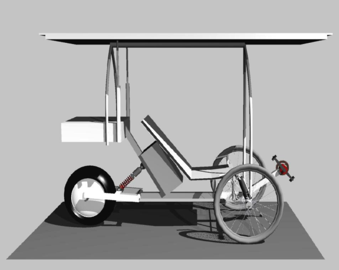 | Figure 1. A 3D view of the solar vehicle’s design |
2.2. Energy Contributions
The solar vehicle combines the use of electric energy from three different sources: a) photovoltaic solar energy, b) energy obtained through human contribution, and c) batteries. The block diagram in Figure 2 depicts the energy systems that constitute the base of the solar vehicle, jointly with the accumulator of these energies. The photovoltaic solar energy is obtained from five photovoltaic solar panels that supply the battery through the panel’s Maximum Power Point Tracker (MPPT), operating in buck mode.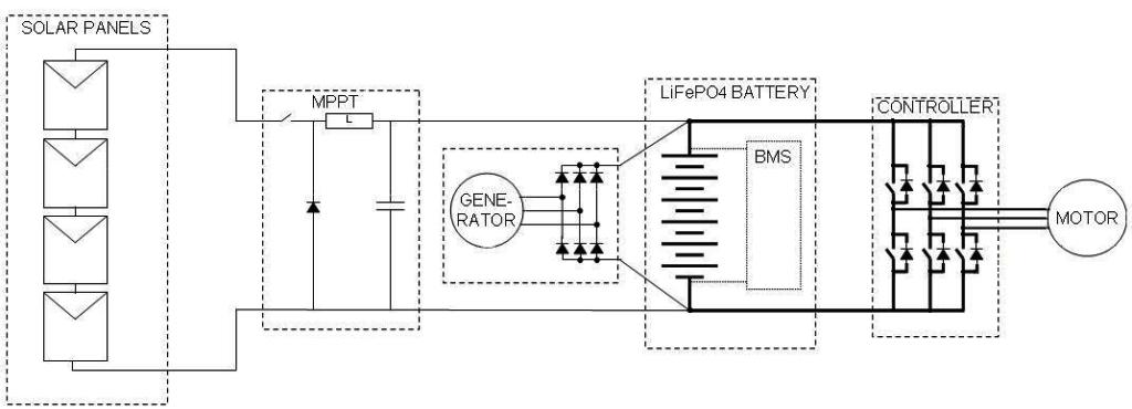 | Figure 2. Block diagram of the energy systems |
Thus, it is possible to pick up the highest energy of the direct radiation depending on the incidence angle. Figure 2 also shows the converter, the speed control and regenerative braking module, for recouping some degree of energy during stopping, and the in-wheel electric motor.The physical capacities of the vehicle rider are used for a complementary energy contribution. In this sense, the rider operates a pedal mechanism in recumbent position arranged in the front of the vehicle that activates a three-phase brushless generator, acting as an energy contributor. An AC/DC rectification is necessary before to supply a convenient DC voltage level to the battery. A three-phase rectifier was implemented for such a purpose.The batteries constitute the storage system of the electric energy and contribution when the electric motor requirements have a power request greater than the input. The battery pack has an intelligent charge-discharge system called Battery Management System (BMS) that monitors the voltage of each cell, protecting it against overloads and charge imbalances, thus ensuring the capacity of the entire pack at different temperatures and its working life[13].
2.3. Electric Generator
A combination of human body’s lower extremities muscles is used in a conventional bicycle to move it by means of a cyclical movement at speed between 60 and 80rpm, depending on the nature of the bicycle rider[14]. The consulted bibliography allows analysing some values that quantify the power that a human being can supply without suffering physical damage. Several factors such as temperature, pressure, altitude, and humidity have an important influence. Considering this factors, a human being of a normal physical constitution can pedal for several hours without suffering fatigue, and a rapid recovery is possible with a constant pedaling equivalent to approximately 75W[15]. However, the bicycle rider can realize a work of three or four times more than the aforementioned value to reach approximately 300W in very short periods of time. This energy is used as contribution for providing, in normal rhythm, a power supply in a range of 30-70W, depending on the charge state of the battery.The system consists of a chain-based transmission between a driver gear wheel and a sprocket wheel assembled on the electric generator’s axle. The main parts of the system are the following ones: a) 54 tooth driver gear wheel, b) pedals attached to the driver wheel, c) 12 tooth sprocket wheel, d) chain, e) three-phase brushless generator, and f) AC/DC rectifier.
2.4. Photovoltaic Solar Panels
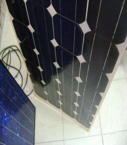
The solar modules constitute the main electricity source and are responsible for the energy generation used in the vehicle’s operation. The “solar roof” has a rectangular shape (1.2m x 2.5m), imposed by the solar race rules, and consists of an array of 171 monocrystalline solar cells distributed in 5 solar panels, 4 of them have 36 cells and 27 the remaining one. An array of 4 serial connected panels was implemented to obtain the necessary 48V with the possibility to have a fifth panel to be connected for generating energy too. Thus, by means of the “solar roof” with an area of 3m2 is possible to obtain a peak power of 445W.The monocrystalline silicon solar cells have a dimension of 125mm x 125mm, and an efficiency of 18% specified for a solar irradiance of 1kW/m2 at 25ºC.Figure 3 shows the solar cells used in this project and the serial interconnection process. Figure 4 shows a solar panel with the solar cells interconnected and encapsulated. The solar cells were interconnected and encapsulated in modules through a process fully carried out in our laboratories.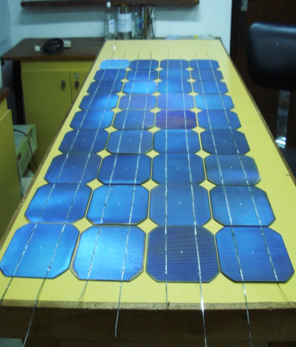 | Figure 3. Interconnection process for solar cells |
 | Figure 4. Monocrystalline solar cells interconnected and encapsulated within a solar panel |
2.5. Battery Choosing
The correct dimensions of the battery establish the autonomy degree of the solar vehicle. The goal is to search for a suitable relation among weight, volume, lifetime, cost, energy density, and environmental impact. At the same time, these factors must be expressed in the lowest possible weight and volume of the vehicle. In our case an exhaustive analysis of alternatives and existing technologies on the market was made for determining a convenient relation among the aforementioned parameters.After carried out a set of trials and a comparative analysis of the main characteristics of different types of energy accumulators[1,13,16,17], a Lithium-Iron-Phosphate (LiFePO4) storage battery composed of 16 arrays in series, each of them with 7 cells in parallel (16S7P) was chosen for obtaining 48V - 40Ah.When compared with classic batteries, LiFePO4 batteries have important characteristics for electric vehicle applications, considering cell average voltage of 3.2V – 3.3V, gravimetric energy density of 100Wh/Kg, volumetric energy density of 200Wh/l and a high cycle life with approximately 2000 cycles (at 80% DOD)[13]. In addition, represents approximately 1/2 of the volume and 1/3 of the weight of the lead-acid battery.With regard to the environmental impact this type of technology is accredited by the Restriction of Hazardous Substances (RoHS) directive.
2.6. Electric Motor Characteristics
The high-efficiency electric traction is achieved through a 48V - 2kW brushless hub-motor provided with a brake disk, capable to reach a speed of 626rpm in its maximum performance point[18]. The motor is provided with a programmable controller to easily change parameters, and obtain diagnostic information[19].The electric motor has the possibility of regenerative braking, i. e., the energy contribution exploiting the vehicle’s dynamic during deceleration.
2.7. Electronic Systems
Electronic systems that are part of the solar vehicle consist of the brushless motor controller, and the modules fully developed in our Faculty, including software and hardware, as follows: a) A switching DC-DC power supply (Vin = 48V, Vout = 24V) for powering the linear actuator that commands the “solar roof” positioning, and light systems, b) A switching DC-DC power supply (Vin = 48V, Vout = 12V) for powering the data acquisition system, c) A switching DC-DC power supply (Vin = 48V, Vout = 19V) for powering a portable PC with USB communication, that runs the software and graphic interface for viewing the physical variables, and d) Signal conditioning modules to measure and monitor the physical variables, including: current produced by photovoltaic and human contribution, respectively, electric motor consumption and temperature, battery voltage, battery temperature, GPS data, and command of actuators.The photograph in Figure 5 shows the rear-assembled structure containing the electronic systems of the solar vehicle. As it can be seen in the Figure there are various electronic modules, including: a) brushless motor controller, b) metallic support for all the switching power supplies, c) portable PC, d) microcontroller-based acquisition system with USB interface for communicating with the PC, e) MPPT module, f) signal conditioning modules and sensors, g) brushless motor current sensing system.In addition, the rear-assembled metallic structure concentrates the wiring for electronic and electric installation, and terminal connections for light systems.As a whole, the vehicle rider can know the current energy condition of the mobile, the position, the ideal speed to reach at determined point with the available energy, and the possibility of acting through the generator if it is necessary. In turn, it has information about the need to modify the angle with regard to the horizontal position of the “solar roof” to obtain best use of the energy. All this information is available on a graphic interface, accessible through an 8-Inch VGA monitor arranged in the front of the vehicle.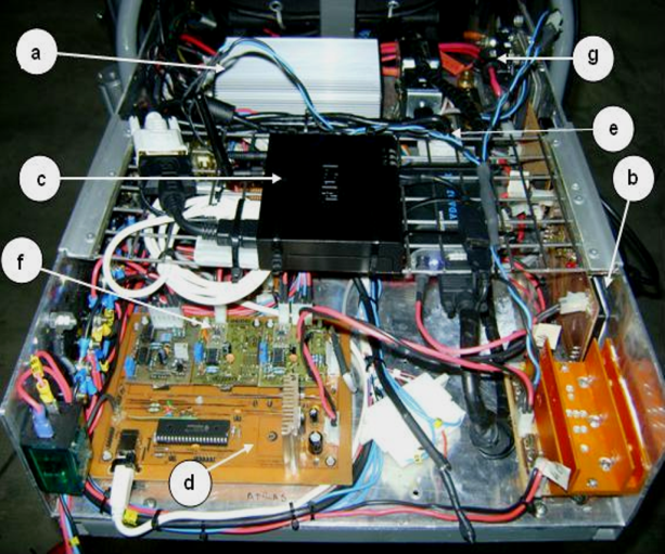 | Figure 5. Electronic systems of the experimental solar vehicle |
3. Results
Figure 6 shows a photograph of the current version of “Pampa Solar” experimental vehicle during a solar cars exhibition previous to the competition across the Atacama Desert.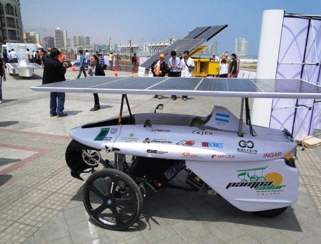 | Figure 6. Experimental solar vehicle “Pampa Solar” |
3.1. Performance of Solar Modules
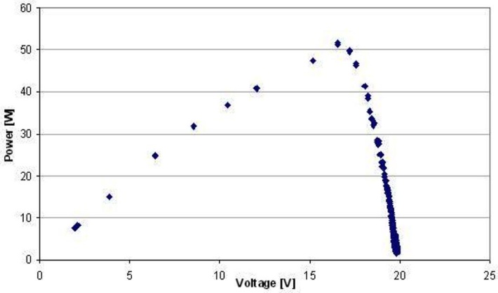
The assembled panels were compared with commercial ones of similar characteristics, obtaining satisfactory results. For such a purpose a PC-based acquisition system was utilised to obtain the voltage and currents produced by the panels loaded through a variable resistor. The results for one solar panel comprised by 36 solar cells and contrasted with a commercial panel of similar characteristics are presented in Table 1, where A is the area of one solar cell in[m2], I is the solar irradiance in[W/m2], Vmax and Imax are the maximum voltage and current obtained from the panel at the point of maximum power Pmax, in[V],[A], and[W] respectively, Voc is the open-circuit voltage and Isc is the short-circuit current.| Table 1. Measured parameters for both assembled and commercial solar panels |
| | Parameter | Solar Panel | | Assembled | Commercial | | A[m2] | 0.014 | 0.013 | | Number of cells | 36 | 36 | | I[W/m2] | 600 | 600 | | Isc[A] | 3.93 | 3.28 | | Voc[V] | 19,8 | 20.2 | | Imax[A] | 3.12 | 2.68 | | Vmax[V] | 16.6 | 15.1 | | Pmax[W] | 51.7 | 40.4 |
|
|
The evaluation of the performance of the integrated solar cells has been made by means of the fill factor (FF), as in (1). | (1) |
This is the ratio of the product of maximum obtainable power of the solar panel, determined by Vmax and Imax, to the product of Voc and Isc (theoretical power). In our case, and using the values from Table 1, FF=0.66 for the assembled panel and FF=0.61 for the commercial panel.Figure 7 represents I vs. V characteristic for the assembled panel jointly with the theoretical characteristic determined by the rectangle, thus illustrating the concept of fill factor. Figure 8 shows P vs. V characteristic for the assembled panel in which is possible to observe the peak power point.The efficiency of the panel is obtained through (2) where Nc is the number of the cells integrated within the panel. | (2) |
The efficiency is 17% and 14.5% for the assembled and the commercial panel, respectively.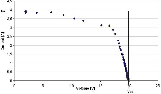 | Figure 7. Characteristic I vs. V for the assembled solar panel |
 | Figure 8. Characteristic P vs. V for the assembled solar panel |
3.2. Vehicle during the Solar Race
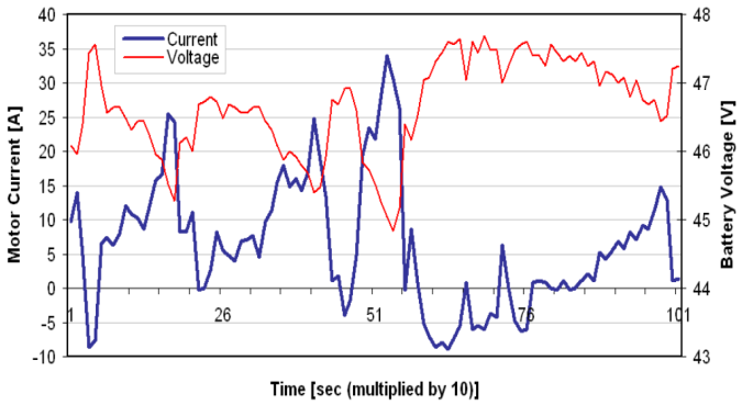
Figure 9 shows a photograph of the solar vehicle travelling around the Atacama Desert, during the solar vehicles race, over a demanding road stretch with marked slopes. This topography is very interesting to analyse the vehicle’s performance in terms of electric motor current requirements and battery voltage levels. The electric motor current takes positive and negative values as shown in Figure 10 that depicts the evolution of the current motor as a function of the time depicted with blue line.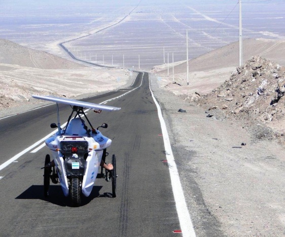 | Figure 9. The solar vehicle travelling around the Atacama Desert |
 | Figure 10. Brushless electric motor current and battery voltage as a function of time |
It is possible to observe the negative values of the motor current on account of the energy recouping during braking and decelerations. In these situations the battery voltage increases its value as it can be seen in Figure 10, indicated with red line. A peak of -8.8A was registered corresponding to battery voltage of 47.6V. In contrast, at the maximum positive peak of the motor current (33.9A) was registered the minimum battery voltage (44.9V).Figure 11 shows the vehicle speed as a function of time over a road stretch with relatively few slopes if it is compared with the case shown in Figure 9. In this case, and taken into account a period of approximately one hour, the vehicle developed an average speed of 33km/h.As final comment, it is important to notice some issues closely related with the convenient utilization of solar energy during the race. As illustrated in Figure 9, the “solar roof” exhibits an inclination due to the rotation movement of 40º over the horizontal axle granted by the solar tracker system. This fact jointly with the available online information of energy balance made possible to obtain the best use of solar energy during the competition.The vehicle was mobilised using at least 50% of its energy provided by the solar panels, as imposed by the race rules. The results have been confirmed during the race, in which the vehicle was awarded with the prize of best use of photovoltaic solar energy in the “Solar Road” category.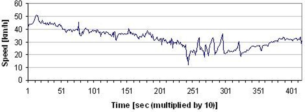 | Figure 11. Vehicle speed as a function of time over a road stretch with few slopes |
4. Conclusions
The main aspects of the design of an experimental solar vehicle based on hybrid system that combines photovoltaic solar energy and human energy contribution was presented and described in this manuscript. Special emphasis has been stressed to the photovoltaic solar energy as main electricity source of the solar vehicle. Excellent results related to transmission, weight, and flexibility were obtained using styrene base polymer to encapsulate the solar cells. The final cost of the solar panel is smaller than the commercial solar modules.The research in different stages of the project led to the utilization of LiFePO4 batteries because of its relevant characteristics for its use in electric vehicles.The obtained results on experimental trials of the energy systems, the tests carried out over photovoltaic solar panels, mechanics, electric and electronic systems are satisfactory. These results have been confirmed during the solar vehicles race in the “Atacama Solar Challenge” in which our experimental vehicle was awarded with the prize of best use of photovoltaic solar energy in the “Solar Road” category.Possible improvements for the vehicle will be proposed in future works, taking into account the zero-emission and the incorporation of new technologies as main guidelines.
ACKNOWLEDGEMENTS
The authors would like to acknowledge the authorities and personnel of the Faculty of Engineering (Universidad Nacional del Centro de la Provincia de Buenos Aires), the Buenos Aires Province Scientific Research Commission (CIC), and the Olavarria City Municipality, for the financial support. Likewise, a special acknowledgement is also extended to companies and institutions that demonstrated their commitment with this project.
References
| [1] | E. J. Caims, “A new mandate for energy conversion: zero emission (electric) vehicles,” in Proc. IEEE 35TH International Power Sources Symposium, 1992, 310-313. |
| [2] | G. Maggeto and J. Van Mierlo, “Electric and electric hybrid vehicle technology: a survey,” in Proc. IEE Seminar on Electric, Hybrid and Fuel Cell Vehicles, 2000, 1/1-11. |
| [3] | S. Matsumoto, “Advancement of hybrid vehicle technology,” in Proc. IEEE European Conference on Power Electronics and Applications, 2005, 1-7. |
| [4] | L. Situ, “Electric Vehicle Development: the past, present & future,” in Proc. 3rd International Conference on Power Electronics Systems and Applications, 2009, 1-3. |
| [5] | H. J. Weiss, H. Weiss, A. N. Lopatkin, and N. N. Lopatkin, “True zero-emission vehicle energy generation and measurement in students' educational project,” in Proc. APEIE 2010, 2010, 86-92. |
| [6] | J. Connors, “On the subject of solar vehicles and the benefits of the technology,” in Proc. ICCEP’07, 2007, 700-705. |
| [7] | G. Rizzo, I. Arsie, and M. Sorrentino, “Solar energy for cars: perspectives, opportunities and problems,” GTAA Meeting, 2010, 1-6. |
| [8] | L. Zhihao and A. Khaligh, “An integrated parallel synchronous rectifier and bi-directional DC/DC converter system for solar and wind powered hybrid electric vehicle,” in Proc. IECON’09, 2009, 3779-3784. |
| [9] | Bin Wu, Fang Zhuo, Fei Long, Weiwei Gu, Yang Qing, and YanQin Liu, “A management strategy for solar panel -battery- super capacitor hybrid energy system in solar car,” in Proc. ICPE & ECCE 2011, 2011, 1682-1687. |
| [10] | D. A. G. Redpath, D. McIlveen-Wright, T. Kattakayam, N. J. Hewitt, J. Karlowski, and U. Bardi, 2011, Battery powered electric vehicles charged via solar photovoltaic arrays developed for light agricultural duties in remote hilly areas in the Southern Mediterranean region, Journal of Cleaner Production, 19(17-18), 2034-2048. |
| [11] | R. Mangu, K. Prayaga, B. Nadimpally, and S. Nicaise, “Design, development and optimization of highly efficient solar cars: Gato del Sol I-IV,” in Proc. IEEE Green Technology Conference, 2010, 1-6. |
| [12] | O. Ustun, M. Yilmaz, C. Gokce, U. Karakaya, and R. N. Tuncay, “Energy management method for solar race car design and application,” in Proc. IEMDC’09, 2009, 804-811. |
| [13] | N. Kularatna, 2011, Rechargeable batteries and their management, IEEE Instrumentation and Measurement Magazine, 14(2), 20-33. |
| [14] | S. S. Wilson, 1973, Bicycle technology, Scientific American, 228(3), 81-91. |
| [15] | F. R. White and D. G. Wilson, Bicycle Science, 2nd ed., Ed. The MIT Press, 1982. |
| [16] | W. Jiayuan, S. Zechang, and W. Xuezhe, “Performance and characteristic research in LiFePO4 battery for electric vehicle applications,” in Proc. IEEE Vehicle Power and Propulsion Conference, 2009, 1657-1661. |
| [17] | T. L. Gibson and N. A. Kelly, 2010, Solar photovoltaic charging of lithium-ion batteries, Journal of Power Sources, 195, 3928-3932. |
| [18] | “Hub Motor 48V–2kW - Performance data”. (2011)[Online]. Available: http://kellycontroller.com/hub-motor-48v-2kwdisc-brake-p-164.html |
| [19] | “Kelly KEB Brushless Motor Controller User’s Manual Rev 3.3”. (2011) Kelly Controls homepage[Online]. Available: . |


 Abstract
 Reference
 Full-Text PDF
 Full-text HTML