-
Paper Information
- Next Paper
- Previous Paper
- Paper Submission
-
Journal Information
- About This Journal
- Editorial Board
- Current Issue
- Archive
- Author Guidelines
- Contact Us
International Journal of Energy Engineering
p-ISSN: 2163-1891 e-ISSN: 2163-1905
2012; 2(1): 9-14
doi: 10.5923/j.ijee.20120201.02
Effect of Compression Ratio on Performance of Combined Cycle Gas Turbine
 Abstract
 Reference
 Full-Text PDF
 Full-Text HTML
Thamir K. Ibrahim 1, M. M. Rahman 1, 2
1Faculty of Mechanical Engineering, Universiti Malaysia Pahang Pekan, Pahang, 26600, Malaysia
2Automotive Engineering Centre, Universiti Malaysia Pahang Pekan, Pahang, 26600, Malaysia
Correspondence to: Thamir K. Ibrahim , Faculty of Mechanical Engineering, Universiti Malaysia Pahang Pekan, Pahang, 26600, Malaysia.
| Email: |  |
Copyright © 2012 Scientific & Academic Publishing. All Rights Reserved.
It is known the performance of a gas turbine (GT) has strong dependence of climate conditions. A suitable solution to minimize this negative effect is to raise inlet turbine temperature and reduce temperature of inlet air to GT compressor. Combined cycles gas turbines (CCGT) are a lot used to acquire a high-efficiency power plant. Increases the peak compression ratio has been proposed to improve the combined-cycle gas-turbine performance. The code of the performance model for CCGT power plant was developed utilizing the MATLAB software. The simulating results show that the overall efficiency increases with the increase of the peak compression ratio. The total power output increases with the increase of the peak compression ratio. The peak overall efficiency occurs at the higher compression ratio with low ambient temperature and higher turbine inlet temperature. The overall thermal efficiencies for CCGT are higher compared to gas-turbine plants.
Keywords: Combined Cycle, Compression Ratio, Gas Turbine, Power, Thermal Efficiency
Cite this paper: Thamir K. Ibrahim , M. M. Rahman , "Effect of Compression Ratio on Performance of Combined Cycle Gas Turbine", International Journal of Energy Engineering, Vol. 2 No. 1, 2012, pp. 9-14. doi: 10.5923/j.ijee.20120201.02.
Article Outline
1. Introduction
- The gas and steam turbines are the greatest means to generate mechanical power. Both gas and steam turbines have been successfully working in large scale to generate the electricity, whereas gas turbine ensures superior thermal efficiency as compared to steam turbine. Different means have been employed by a lot of researchers to get better thermal efficiency of the turbines, particularly the gas turbine. One of the means is to increase the gas-turbine inlet temperatures and decrease the compressor inlet air temperatures, this mean increase the peak cycle temperature ratio. As a consequence of cycle peak temperature ratio, higher exhaust gases temperature results, which means increase the energy loss at the stack[1-2].Many researchers focus on improve the modeling of CCGT power plant system utilizing the Brayton Cycle gas turbine and Rankine Cycle steam turbine with air (gases) and water (steam) as working fluids achieve efficient, reliable, and economic power generation as shown in Figure 1. Current commercially available generation CCGT power plants achieve total thermal efficiency typically in the 50- 60% Lower Heating Value range[3-4]. Further development of simple cycle gas turbine, metal surface cooling technology, and high temperature bleed materials show promise for near term generation power for CCGT power plants capableof reaching more than 60% plant thermal efficiency. Additional the development in gas-turbine technology, as well as increases in steam-turbine cycle temperature and pressure, HRSG stage design enhancement, is expected to achieve further combined-cycle gas-turbine power plants efficiency improvement[5-6]. The combination of the gas-turbine Brayton Cycle and the steam turbine power plant Rankine Cycle complement each other to form efficient CCGT power plants. The Brayton Cycle has high source temperature and rejects heat at a temperature that is conveniently used as the energy source for the Rankine Cycle plant. The most commonly used working fluid for combined-cycle gas-turbine power plants are air and steam[7]. Kaushika et al.[5]. Studied optimum performance of a CCGT power plant; the CCGT power plant has been modelled and simulated. The behaviour of the gas turbine was studied at part load. Results of a sensitivity analysis of the effect of atmospheric temperature on the gas-turbine performance are presented. The best combination of process parameters of steam leaving the steam generator that will give optimum performance of the CCGT power plant were determined at part load operation. Results for the optimum values of thermal efficiency and power output together with values of the decision variables are presented[8]. Khaliq and Kaushik[9] created the simulator of the combined-cycle co-generation power plant. The simulator is built by the mathematical model, which is a model for power plant modelling. The simulator is divided into two parts, the first is a simulation of fluid flow in the power plant, and the other part is a simulation of the control system of the plant[10, 11].In the present work, a parametric thermodynamic analysis of a combined-cycle gas turbine is undertaken. The effect of operating parameters, including peak pressure ratio, gas-turbine peak temperature ratio, isentropic compressor and efficiency and air fuel ratio, on the overall plant performance is investigated.
2. Modeling of Combined Cycle Gas Turbine
- A combined cycle gas turbine power plants having Brayton cycle based topping cycle and Rankine cycle based bottoming cycle has been considered for the present study and analysis. Gas turbine power plants consist of four components, compressor, combustion chamber, turbine and generator. Air is drawn in by the compressor and delivered to the combustion chamber. Liquid or gaseous fuel is commonly used to increase the temperature of compressed air through a combustion process. Hot gases leaving the combustion chamber expands in the turbine which produces work and finally discharges to the atmosphere (state 1, 2, 3 in Figure 2)[12,13]. The waste exhaust gas temperature from gas turbine decreases as it flows into the heat recovery steam generator (HRSG), which consists of superheater, evaporator and economizer. Then the HRSG supplies a steam for the steam turbine in producing electricity. In the latter, the waste condensate from the steam turbine will be flowed into a condenser, where cooling water transfers waste heat to the cooling tower. In the final stage, feed water is the output from a condenser, which is suctioned by the feed water pump and sent to the heat recovery steam generator[5, 14].
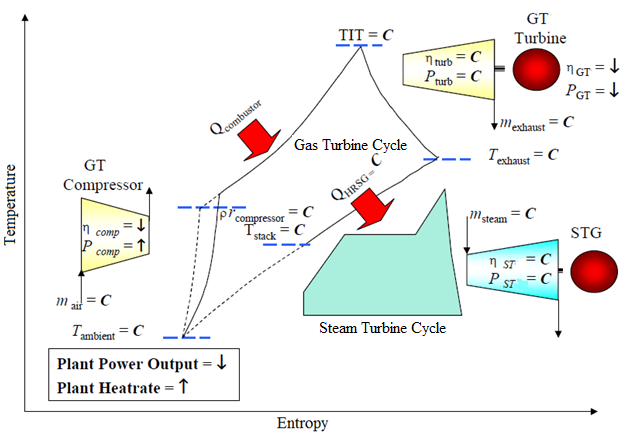 | Figure 1. Temperature-entropy diagram for CCGT power plant |
2.1. Gas Turbine Model
- It is assumed that the compressor efficiency and the turbine efficiency are represent and respectively. The ideal and actual processes on the temperature-entropy diagram are represented in full and dashed line respectively as shown in Figure 2[15].
2.1.1. Air Compressor Model
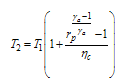
- Using the first law of thermodynamic and knowing the air inlet temperature to compressor, pressure ratio (rp) and isentropic efficiency for compressor, we can determine the following parameter: The compressor compression ratio (rp) can be defined as[16]:
 | (1) |
 | (2) |
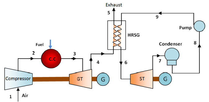 | Figure 2. The schematic diagram of combined cycle gas turbine power plant. |
 | (3) |
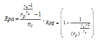 | (4) |
 and
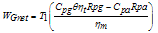
and  .The work of the compressor (Wc) when blade cooling is not taken into account can be calculated as:
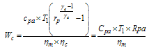 | (5) |
 in Kelvin.
2.1.2. Combustion Chamber Model
- From energy balance in the combustion chamber[17]:
 | (7) |
 is fuel mass flow rate (kg/s),
  is air mass flow rate (kg/s), LHV is low heating value, T3 = TIT = turbine inlet temperature Cpf is specific heat of fuel and Tf is temperature of fuel.The specific heat of flue gas (
 ) is given by Naradasu et al.[19]:
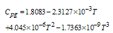 | (8) |
 peak cycle temperature ratio.
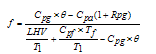 | (9) |
2.1.3. Gas Turbine Model
- The exhaust gases temperature from gas turbine is given by Eq. (10).
 | (10) |
 where Tg1 is the inlet gases temperature to HRSG. The shaft work (Wt) of the turbine is given by Eq. (11).
 | (11) |
 | (12) |
 | (13) |
 | (14) |
 | (15) |
 ) can be determined by Eq. (16)[16]:
 | (16) |
 | (17) |
2.2. Steam Turbine Cycle Model
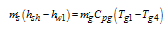
- It is assumed that the steam turbine efficiency and the pump efficiency are represented and respectively. The ideal and actual processes on the temperature-entropy diagram are represented in full and dashed line respectively[20]. Heat recovery steam generator model (HRSG): A single pressure HRSG is considered here as a common type for the combined cycle gas turbine power plant. By applying the energy balance for gas and water in each part of the HRSG the gas temperature and water properties are calculated by solving the following equations:Heat available with exhaust gases from gas turbine can give as;
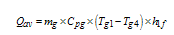 | (18) |
 ) is the heat loss factor typically ranging from 0.98 to 0.99[21].The superheater duty is:
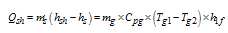 | (19) |
 | (20) |
 | (21) |
 | (22) |
 | (23) |
 | (24) |
 | (25) |
 | (26) |
 | (27) |
 | (28) |
 | (29) |
3. Results and Discussion
- The parameter influence in terms of cycle peak temperature ratio, compression ratio, air to fuel ratio, and isentropic compressor and turbine efficiency, on the performance of the combined-cycle gas-turbine cycle power plants are presented in this section. The effects of these parameters on the power output and efficiency are obtained by the energy-balance utilizing MATLAB10 software. Figure 3 shows the variation of compression ratio, isentropic compressor and turbine efficiencies on overall thermal efficiency for CCGTPP. It is noticed that the overall thermal efficiency increases with compression ratio as well as isentropic compressor and turbine efficiency. However, the variation of overall thermal efficiency is minor at the lower compression ratio while it is very significant at the higher compression ratio for both isentropic compressor and turbine efficiency. The thermal efficiency with effect high compression ratio increases from 52.5% to 60.6% when the isentropic compressor efficiency increases from 75% to 95% as shown in Figure 3(a), however, the thermal efficiency increases from 46.8% to 62,9% with the increase of the isentropic turbine efficiency from 75% to 95% as shown in Figure 3(b).Figure 4 shows the effect of variation of compression ratio and turbine inlet temperature on the total power output and overall thermal efficiency. Figure 4(a) shows the total power output increases with decreases the compression ratio as well as higher turbine inlet temperature. In Figure 4(b), it can be seen that the overall thermal efficiency increases with compression ratio at higher turbine inlet temperature. The deviation of overall thermal efficiency at the lower compression ratio is not significant while the variation at the higher compression ratio is vital for overall thermal efficiency. The turbine inlet temperature is very crucial for the higher compression ratio. The overall thermal efficiency at high compression ratio increases from 54.8% to 61.3% with the increase of the turbine inlet temperature from 1150 to 2050K.Figure 5 shows the comparison between simulated power outputs combined cycle and simple gas turbine versus practical results from the Baiji gas turbine power plants. It can be seen that the power output from the combined-cycle gas-turbine power plant is much higher compare to single shaft gas turbine as well as the practical single (Baiji Gas Turbine Power Plant) gas-turbine power plants.
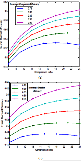 | Figure 3. Effect of compression ratio on overall thermal efficiency: a) Isentropic compressor efficiency b) Isentropic turbine efficiency |
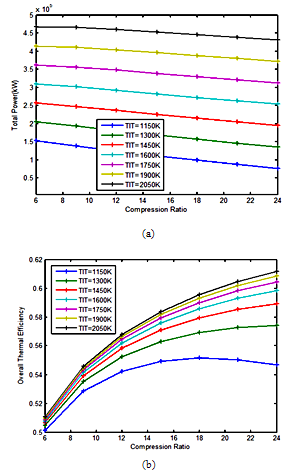 | Figure 4. Variation of compression ratio and turbine inlet temperature on (a) Total power output; (b) Overall thermal efficiency |
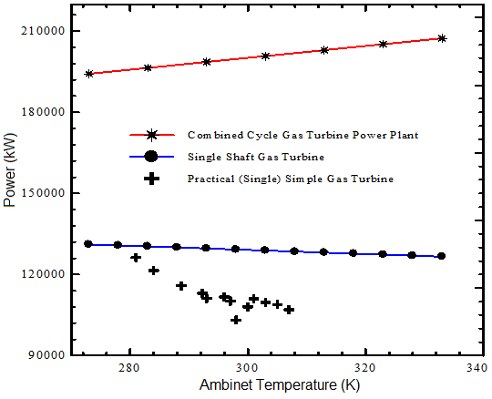 | Figure 5. Comparison between combined cycle and simple gas turbine versus practical Baiji gas turbine power plant |
4. Conclusions
- The complete model for the combined-cycle gas-turbine power plant with effect the gas-turbine peak compression ratio has been used for carrying out the thermodynamic study. The simulated modelling results show as follows:i) The compression ratios, air to fuel ratio as well as the isentropic efficiencies are strongly influenced on the overall thermal efficiency of the combined-cycle gas-turbine power plant.ii) Higher overall efficiencies for combined-cycle gas turbine compared to gas-turbine plants. Efficiency quoted range about 61%.iii) The overall thermal efficiency increases and total power output decrease linearly with the increase of the compression ratio with constant turbine inlet temperature. iv) The peak overall efficiency occurred at the higher compression ratio with the higher cycle peak temperature ratio as well as higher isentropic compressor and turbine efficiencies.
ACKNOWLEDGEMENTS
- The authors would like to thank Universiti Malaysia Pahang for providing laboratory facilities and financial support under Doctoral Scholarship scheme (No. GRS100332).