-
Paper Information
- Next Paper
- Previous Paper
- Paper Submission
-
Journal Information
- About This Journal
- Editorial Board
- Current Issue
- Archive
- Author Guidelines
- Contact Us
International Journal of Energy Engineering
p-ISSN: 2163-1891 e-ISSN: 2163-1905
2011; 1(1): 19-24
doi: 10.5923/j.ijee.20110101.04
Investigation of the Performance Parameters of an Experimental Plate Heat Exchanger in Single Phase Flow
 Abstract
 Reference
 Full-Text PDF
 Full-Text HTML
S. D. Pandey , V. K. Nema
Department of Mechanical Engineering, M.N. National Institute of Technology, Allahabad, 211004, India
Correspondence to: S. D. Pandey , Department of Mechanical Engineering, M.N. National Institute of Technology, Allahabad, 211004, India.
| Email: |  |
Copyright © 2012 Scientific & Academic Publishing. All Rights Reserved.
Experiments were conducted to determine the heat transfer characteristics for fully developed flow of air and water flowing in alternate corrugated ducts. The test section was formed by three identical corrugated channels having corrugation angle of 30o with cold air flowing in the middle one and hot water equally divided in the adjacent channels. Sinusoidal wavy arcs connected with tangential flat portions make the said corrugation angle with transverse direction. The Reynolds number based on hydraulic diameter varied from 750 to 3200 for water and from 566 to 2265 for air by changing the mass flow rate of the two fluids. The Prandtl numbers were approximately constant at 2.55 for water and 0.7 for air. The various correlations obtained are Num=0.247Re0.83 and Num=0.409Re0.57 for water and air, respectively and f = 2.014Re-0.12 for air channel.
Keywords: Plate Type Heat Exchanger, Corrugated Channel, Nusselt Number, Friction Factor, Forced Convection
Cite this paper: S. D. Pandey , V. K. Nema , "Investigation of the Performance Parameters of an Experimental Plate Heat Exchanger in Single Phase Flow", International Journal of Energy Engineering, Vol. 1 No. 1, 2011, pp. 19-24. doi: 10.5923/j.ijee.20110101.04.
Article Outline
1. Introduction
- Today a plate heat exchanger (PHE) is universally used in many fields; heating and ventilation, breweries, dairy, food processing, pharmaceuticals and fine chemicals, petroleum and chemical industries, power generation, offshore oil and gas production, onboard ships, pulp and paper production etc. PHEs also find applications in water to water closed circuit cooling water systems using a potentially corrosive primary cooling water drawn from sea, river, lake, or cooling tower, to cool, non-corrosive secondary liquid flowing in a closed circuit. Design theory for PHEs is given at length in reference[1], while its application was dealt in reference[2].A compact heat exchanger has been arbitrarily defined as having an area density greater than 700m2/m3 for units operating in gas streams and in excess of 300m2/m3 when operating in liquid or two-phase stream[3]. The use of corrugated channel results in a more complex flow structure and improves the heat transfer by as much as two or three times compared to a conventional straight channel[4,5]. The sinusoidal wavy plate arrangements and channel geometries improved the heat transfer performance by increasing the surface area and prompting the formation of vortex in the flow[6,7]. The symmetric arrangement yields a superior heat transfer performance to an asymmetric arrangement. Unfortunately, the geometric parameters are not clearly expressed. Due to the high heat transfer efficiency of the plates, a PHE is very compact when compared to a shell and tube heat exchanger with the same heat transfer capacity. Some of the research works on plate heat exchangers pertain to heattransfer and pressure drop characteristics of an absorbent salt solution in a commercial plate heat exchanger[7]. A Low cost route was developed to heat recovery in the Plate heat exchanger[8].Beloborodov and Volgin[9] investigated heat transfer in a corrugated duct having an inter wall spacing and corrugation angle. The experimental apparatus is not well defined, but it appears to have been a two-fluid heat exchanger, with no direct measurement of wall temperature, such that the obtained heat-transfer coefficients are averages for the device as a whole. The corrugations were formed from sheet metal and thus could not have had the sharp-edged corrugation peaks of the present work. In light of these uncertainties, it is difficult to accord a great deal of generality to the correlations presented in[9]. The research performed by Goldstein[10] is another contribution to the literature on heat transfer in corrugated flow passages. This work was largely concerned with the low Reynolds number range from 150 to 2000, within which secondary flows were identified by high-resolution local mass-transfer measurements. The corrugated channel of[10] had only two corrugation cycles, and thus the Sherwood number results are applicable only to the region of flow development near the inlet of the corrugated duct. A situation which has certain similarities to corrugated-duct flow is flow through tube banks, commonly encountered in heat exchangers. The similarities include periodic regions of both recirculation and forward flows. Tube-bank information[11,12] will be called upon to provide perspective for the present Nusselt-Reynolds-Prandtl correlations. O'Brien and Sparrow[13] conducted the trial in a corrugated duct having an inter wall spacing employing two different but complementary apparatuses, one was for heat transfer correlations and other for pressure drops. This was for only one fluid which flowed through the corrugated duct. Lin et al.[14] in their experimental work, investigated heat exchange between two fluids air and water, the former flowed through the central corrugated duct and the latter through the outer channels having one surface corrugated and other flat. Dimensional analysis was performed and the significance of various dimensionless groups determined. Experimental work by Liu and Tsai[15] for cross corrugated channel of a small plate heat exchanger showed that the laminar flow changes to turbulent at Re > 300, while the work by Focke et al.[16] on corrugated channel for 30o corrugation angle mentions the critical Re to be 400. It was observed in the CFD model and laboratory tests[17,20] that the flow was turbulent for Re in the range 600 to 1700.In continuation of the experimental studies an experiment was conducted for finding heat transfer coefficient and friction factor in corrugated channel. Ten wavy cycles were used against two in paper by[14]; outer channel have both surface corrugated unlike in[14] where only one surface was corrugated. The setup is described below.
2. Fabrication of Plates
- The separate plate heat exchangers were fabricated to make horizontal channels formed by corrugated plates in the front view as sketched in Figure 1.
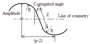 | Figure 1. Geometry of a plate segment. |
 The above-mentioned dimensions were obtained by making a wooden pattern in the carpentry shop and then giving the required shape to the sheets using the pattern.
 3. Experimental Setup
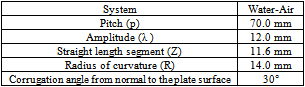
- The experimental setup, described schematically in the Figure 2 is fabricated to investigate the heat transfer characteristics in a plate heat exchanger having three identical channels formed by Galvanized Iron corrugated plates of 24 gauge.
 | Figure 2. Schematic of the experimental setup. |
3.1. Specifications of the Experimental Setup
- Length of the test section = 70cm Width of the test section = 11cm Height of the test section =25cm Developed length of the corrugated plate = 82cm Gap between two corrugated plates = 5cm Dimensions of the water container = 30cm× 30cm
3.2. Experimental Procedures
- During experiments, hot water was made to flow through the two outer corrugated channels to maintain the channel surfaces at an approximately constant temperature. Thermocouples wrapped in copper tubes and inserted in the front cover plate of the test section were used to record the bulk temperature of air and water. The side effect was negligible due to small aspect ratio of the channels and thus the variations in the transverse direction of a channel could be neglected. In the experiments, the temperature distribution in the horizontal middle planes of the channels was measured using thermocouples positioned at 19 different locations along the length of the channels in the water- and air-loop with 3 and half digit potentiometer. The temperatures of the inlet and outlet air and water were measured with mercury-in-glass thermometers. The pressures of the air at the inlet and outlet of the test section were measured with the pressure gauges[21]. Experiments were conducted with Reynolds number varying between 566 to 2265 for air and 750 to 3200 for water by varying their flow rates. Nusselt number and friction factor were then determined.
4. Numerical Methodology
- Assuming heat loss to the surroundings to be negligible, heat transfer rate across an elemental heat exchanger is given by,
 | (1) |
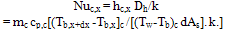 | (2) |
 | (3) |
 (4)The effectiveness of the PHE is calculated from experimental observations.The pressure drop Δph and Δpc on hot and cold fluid sides are calculated from experimental observations and theoretical formulae as given below. Pressure drops for the fluids,Δph = (ph,i – ph,o); Δpc = (pc,i – pc,o)Friction factor f is found form the following relationship:Experimentally obtained values of Nusselt and friction factor may be compared with the following correlations, available in the literature. (i) Focke correlations[1] for a) Mean Nusselt number (Num) is given below:Corrugated plates with plate corrugation angle β = 30o: Num = jcp.Re.Pr1/3(μw/μ)n where jcp = 0.80 Re-0.477 (for 100
5. Results and Discussion
- Experiments were conducted with Reynolds number varying between 566 to 2265 for air and 750 to 3200 for water by varying the flow rates of the fluids. Nusselt number and friction factor were then determined.The observations for the typical combination of air- and water-flow rates for counter flow are given in Table 1.
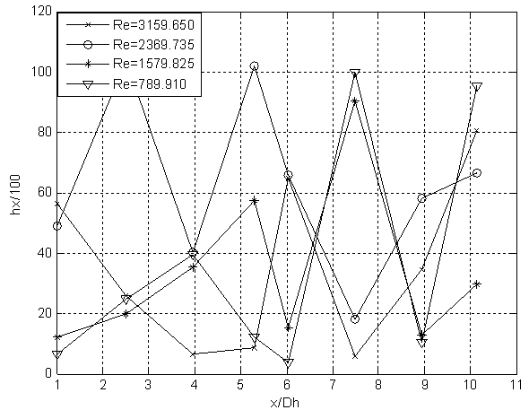 | Figure 3. Variation of hx along channel length (For water). |
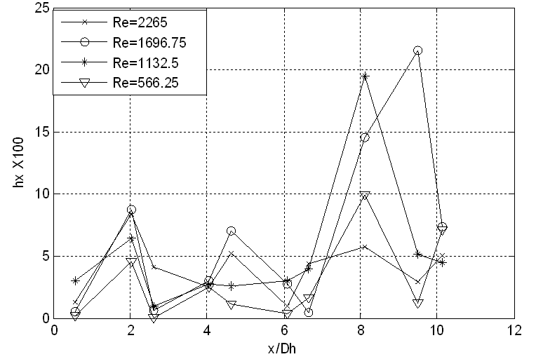 | Figure 4. Variation of hx along channel length (For Air). |
5.1. Nusselt Number
- The mean heat transfer coefficient varied from 162.73 W/m2K to 204.18 W/m2K and hence Num varied from 15 to 33 for air. Corresponding values for water were 633.42 W/m2K, 2029.17W/m2K, 65 and 210. The variation of average Nusselt number, Num with Reynolds number is given in Figures 3 and 4 for the two fluids.The experimental data has been compared with those calculated using the Dittus-Boelter equation for constant wall temperature for smooth tubes, and Brien & sparrow[13], Cooper and Usher[18] and Focke[1] correlations for corrugated plates. While comparing with Focke[1] correlation it is assumed that the correlation for Num and f which are valid up to Re= 50000 and 10000, respectively.
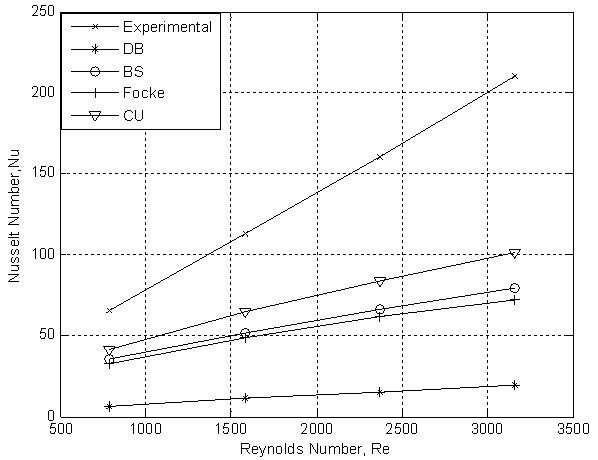 | Figure 5. Comparison of experimental and theoretical Nusselt numbers (For Water). |
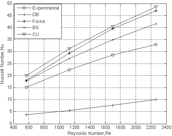 | Figure 6. Comparison of experimental and theoretical Nusselt numbers (For Air). |
5.2. Friction Factor
- Experimental friction factor was compared with the values obtained using Focke and Kumar correlations and the comparison is shown in Figure 7. Theoretical friction factor using Kumar empirical correlation[19] is also included in this Figure.
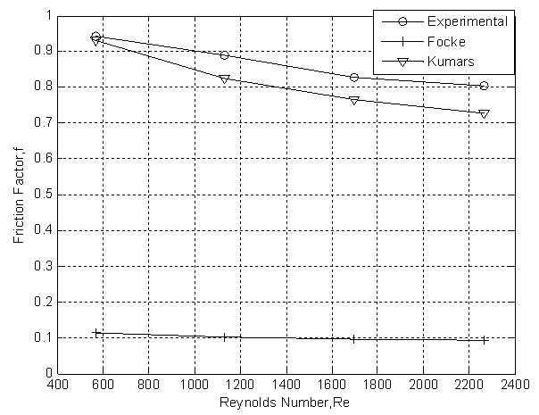 | Figure 7. Comparison of experimental and theoretical friction factor (For Air). |
5.3. Effectiveness
- Effectiveness of this experimental corrugated PHE was found as 81%.
6. Goodness of Fit for Various Curves
- The calculated in terms of the following statistical parameters namely, Standard deviations (s) and Square of the correlation coefficient (r2), defined by
 Values of s and r2 for Nusselt number Num are 0.3386 and 0.9997, respectively and those for friction factor f are 0.0723 and 0.998, respectively.
7. Uncertainty of Measurements
- Estimate of experimental errors on the local Nusselt number (Nux), effectiveness (є), and friction factor (f) associated with the use of equation (2), (5) and (6) was conducted taking into account the uncertainties (σ) associated with each of the independent variables.The uncertainty WR+ , arising in calculating a result R+ due to several independent variables, is given as follows;
 where the result R+ is a given function of the independent variables X1,X2,...Xn and w1,w2,...wn are uncertainties in the independent variables[20]. Uncertainty calculations showed maximum value of 2.8, 5.3, 4.0, and 6.4% in results for Reynolds number, Nusselt number, Prandtl number and friction factor, respectively. The individual contributions to the uncertainties of the non-dimensional parameters, for each of the measured physical properties are summarized in Table 2.
|
8. Conclusions
- The test section was formed by three identical corrugated channels having corrugation angle of 30o with cold air flowing in the middle one and hot water equally divided in the adjacent channels. Sinusoidal wavy arcs connected with tangential flat portions make the corrugation angle with transverse direction. The Reynolds number based on hydraulic diameter varied from 750 to 3200 for water and from 566 to 2265 for air the inlet Prandtl numbers for both the fluid were approximately constant. Experimental investigations are done by changing the mass flow rate of air and water. The pressure drop and heat transfer characteristics in the corrugated channel of a plate heat exchanger were found. Dimensionless correlations for Num have been developed for both air and water, and friction factor for air only, for volume flow rates 200 lpm, 150 lpm, 100 lpm, 50 lpm of air and mass flow rates 0.244kg/s, 0.1533kg/s, 0.1022kg/s, 0.0511kg/s of water, based on experimental results. It is found that Nux depends on Re and x/Dh. Friction factor was found to depend on Re. The magnitudes of the Num and friction factor are high when compared to conventional pipe flows. The mean heat transfer coefficient varied for air from 162.73W/m2K to 204.18W/m2K and hence Num varied from 15 to 33. Corresponding values for water were 633.42W/m2K, 2029.17W/m2K, 65 and 210. Correlations found for Nusselt numbers are Num=0.247Re0.83 for water a Num=0.409Re0.57 for air. Similarly the friction factor varied from 0.803 to 0.943 for air and the correlation for its friction factor was found as f = 2.014Re-0.12. Effectiveness of this experimental corrugated PHE was found as 81%.
References
| [1] | Shah, R. K., Focke, W. W., 1988, Plate heat exchangers and their design theory, Heat transfer equipment design, Hemisphere Publishing Corporation, pp. 227-254 |
| [2] | Mehta, S. K., 1988, Heat Exchanger in heavy water reactor system, Heat transfer equipment design, Hemisphere Publishing Corporation, pp. 337-349 |
| [3] | Reay, D. A., 2004, Compact Heat Exchangers, Enhancement and Heat Pump. Int. J. of Refrigeration, 25, 460-470 |
| [4] | Incorpera, F. P., and Dewitt, P. D., Fundamentals of Heat Transfer, John Wiley and Sons; V Ed, 2004 |
| [5] | Goldstein, L. Jr, Sparrow, E. M., 1977, Characteristics for Flow in Channel. Int. Heat transfer; 05: 205-209 |
| [6] | Nishimura, T., Murakami, S., Arakawa, S., Kawamura, Y., 1990, Flow observations mass transfer characteristics in symmetrical wavy walled channel at moderate Reynolds numbers for steady flow., Int. J. Heat Mass Transfer, 33, 835-845 |
| [7] | Warnakulasuriya, F. S. K., Worek, W. M., 2008, Heat Transfer and Pressure Drop Properties of High Viscous Solutions in Plate Heat Exchangers., Int. J. of Heat and Mass Transfer, l (51), 52-67 |
| [8] | Lamb, B. R., 1982, Plate Heat Exchangers – A Low-Cost Route to Heat Recovery, Heat Recovery Systems, 2(3), 247-255. |
| [9] | Beloborodov, V. G., Volgin, B.P., 1971, Heat Transfer and Pressure Drop in Heat Transfer Equipment with Slot Channels of Varying Cross Section., International Chemical Engineering,11, 229-233 |
| [10] | Goldstein, Leonardo Jr., Sparrow, E. M., 1977, Heat and Mass Transfer Characteristics for Flow in a Corrugated Wall Channel., ASME journal of heat transfer, 91, 187-195. |
| [11] | Zhukauskas, A., 1972, Heat Transfer from Tubes in Cross flow., Advances in Heat Transfer, 8, 93-160 |
| [12] | Grimison, E. D., 1937, Correlation and Utilization of New Data on Flow of Gases over Tube Banks. Trans., ASME, 59, 583-594 |
| [13] | Brien, J. E. O., Sparrow, E. M., 1982, Corrugated-Duct Heat Transfer, Pressure Drop, and Flow Visualization., ASME journal of heat transfer, 104, 410-416 |
| [14] | Lin, J. H., Huang, C. Y., Su, C. C., 2007, Dimensional Analysis for the Heat Transfer Characteristics In The Corrugated Channels of Plate Heat Exchangers., International Communications in Heat and Mass Transfer, 34, 304–312 |
| [15] | Liu, F. B., Tsai, Y. C., 2009, An experimental and numerical investigation of fluid flow in a cross corrugated channel., Applied Thermal engineerin, 4, 207- 214 |
| [16] | Focke, W. W., Knibbe, P. G., 1986, Flow visualization in parallel plate duct with corrugated wall. J. Fluid Mechanical, 165, 73-77 |
| [17] | Tsa, Y. C., Liu, F. B., Shen, P. T., 2009, Investigation of the pressure drop and flow distribution in a chevron-type plate heat exchanger. International communications in heat and mass transfer, 36, 574-578 |
| [18] | Cooper, A., Usher, J. D., Friction Factor Correlations. HemisphereHandbook of Heat Exchanger Design, G. F. Hewitt Co., Hemisphere,Washington DC,1990 |
| [19] | Kakac, S., Liu, H., Heat Exchangers: Selection, Rating and Thermal Design. CRC, Washington, DC, Chap. 10, 2002 |
| [20] | Pandey, S. D., Nema, V. K., 2011, An experimental investigation of exergy loss reduction in corrugated plate heat exchanger. Energy, 36 (5), 2997-3001 |
| [21] | Pandey, S. D,. Nema, V. K., 2011, Experimental investigation of heat transfer and friction factor in a corrugated plate heat exchanger. International Journal of Energy and Environment, 2( 2),287-296 |