Xiaodong Liang 1, Y. Luy 2
1Edmonton Product Center, Schlumberger, 10431 35A Ave., Edmonton, Alberta, T6J 2H1, Canada
2Research and EMS, Schlumberger, 42 Rue Saint Dominique, Paris, 75007, France
Correspondence to: Xiaodong Liang , Edmonton Product Center, Schlumberger, 10431 35A Ave., Edmonton, Alberta, T6J 2H1, Canada.
| Email: |  |
Copyright © 2012 Scientific & Academic Publishing. All Rights Reserved.
Abstract
Non-characteristics harmonics including even and 3rd harmonics commonly exist in the electrical power systems but in small amount which are usually below IEEE Std 519-1992 limits. However, in some cases significant amount of non-characteristic harmonics might be present in an industrial facility, which could be an indication of unhealthy power systems. Two case studies are performed in this paper. Case study 1 is about an even harmonic issue in a large mining system, where large 3rd harmonic currents are also present. Case study 2 is a triplen harmonic issue at the input of multiple variable frequency drives experienced in an oil field distribution system. The root cause for even harmonics in Case 1 is the malfunction of two large rectifiers in the mining facility, while the root cause for 3rd harmonics in both cases is the voltage unbalance issue from the utility side. The two case studies verify that non-characteristic harmonics can serve as an indication for unhealthy power systems. When they are detected in unusually large amounts, an analysis and troubleshooting is always recommended in order to have a stable and reliable operation of electrical power systems.
Keywords:
Uncharacteristic Harmonics, Even Harmonics, 3rd Harmonics, Resonance, Voltage Unbalance
Cite this paper:
Xiaodong Liang , Y. Luy , "Identification of Unhealthy Power Systems with Non-Charateristic Harmonics", International Journal of Energy Engineering, Vol. 1 No. 1, 2011, pp. 12-18. doi: 10.5923/j.ijee.20110101.03.
1. Introduction
Due to the wide application of non-linear loads, harmonics pollution is one of the main concerns for the power systems. Although great progress has been made on harmonic mitigation by manufacturers of nonlinear devices, industry facilities and utility companies, serious harmonic issues can still be present in electrical power systems especially when ill conditions happen either caused by utility companies or by end users in industrial facilities.Variable frequency drives (VFDs) are most widely used in industrial facilities. Characteristic harmonics defined by IEEE std. 519-1992 are based on various system configurations of VFDs[1]. Except some special loads such as arc furnaces[1] and railway traction systems which produce even harmonics and other non-characteristic harmonics into the system, most industrial facilities with VFDs only have characteristic harmonics and some small amount of non-characteristic harmonics which are usually under the even and triplen harmonics limits proposed by IEEE std. 519-1992. Therefore, when large amount of non- characteristic harmonics are present in a power system, it usually indicates that the system is unhealthy and that troubleshooting is required to determine the root causes of the probl-em.Non-characteristic harmonics are investigated in[2-9]. It is explained in[2] that non-characteristic harmonics are caused by unbalanced voltage magnitude or phase non-symmetry. The amplitude of non-characteristic harmonics increases with increasing voltage non-symmetry. Two cases are investigated in this paper for two industrial facilities showing large content of non-characteristic harmonics. The first case is for a mining power system with two rectifiers rated at 12MW each and with a set of harmonic filters installed. Extensive investigation is conducted for this system based on both measurements and computer simulation results. The second case is for an oil field distribution system with multiple VFDs. The issue for this system is that current waveforms at the input of VFDs are seriously distorted.
2. Characteristics and Noncharacteristic Harmonics of Rectifiers
IEEE std. 519-1992[1] proposes harmonic currents generated at a bridge rectifier for an ideal condition. “Ideal” is based on an assumption that dc current has no ripple and the dc current is transferred from one phase to another the instant the voltage on the incoming phase exceeds the voltage on the outgoing phase[1]. The harmonic current components for ideal condition are derived by the following equations[1]: | (1) |
 | (2) |
 | (3) |
where,h – harmonic orderk and m – any positive integerq – pulse number of the rectifier circuitIh – the amplitude of the harmonic current of order hI1 – the amplitude of the fundamental currentFor a 6-pulse rectifier or a variable frequency drive (VFD), the characteristic harmonic currents are 5th, 7th, 11th, etc. For VFDs using phase multiplication technique such as 12-pulse and 18-pulse mitigating input harmonics, some harmonic currents can be cancelled compared to 6-pulse drives. As states in IEEE Std 519-1992, if m six-pulse rectifier sections [1]:Have the same transformer ratioHave transformers with identical impedancesAre phase shifted exactly 60/m degrees from each otherAre controlled at exactly the same delay angle, andShare the dc load current equally| Table 1. Voltage harmonic distortion limits based on IEEE std. 519-1992 |
| | Voltage Harmonic Distortion Limits | | Bus Voltage at PCC | Individual Voltage Distortion, % | Total Voltage Distortion, % | | 69 kV and below | 3.0 | 5.0 | | 69.001 kV through 161 kV | 1.5 | 2.5 | | 161.001 kV and above | 1.0 | 1.5 | | NOTE: High-voltage systems can have up to 2.0% THD where the cause is an HVDC terminal that will attenuate by the time it is tapped for a user |
|
|
| Table 2. Current harmonic distortion limits based on IEEE std. 519-1992 |
| | Current Harmonic Distortion Limits for General Distribution Systems(120 V Through 69 000 V) | | Maximum Harmonic Current Distortion in Percent of IL | | Individual Harmonic Order (Odd Harmonics) | | Isc/IL | <11 | 11≤h<17 | 17≤h<23 | 23≤h<35 | 35≤h | TDD | | <20* | 4.0 | 2.0 | 1.5 | 0.6 | 0.3 | 5.0 | | 20<50 | 7.0 | 3.5 | 2.5 | 1.0 | 0.5 | 8.0 | | 50<100 | 10.0 | 4.5 | 4.0 | 1.5 | 0.7 | 12.0 | | 100<1000 | 12.0 | 5.5 | 5.0 | 2.0 | 1.0 | 15.0 | | >1000 | 15.0 | 7.0 | 6.0 | 2.5 | 1.4 | 20.0 | | Even harmonics are limited to 25% of the odd harmonic limits above. | | Current distortions that result in a dc offset, e.g., half-wave converters,are not allowed | | *All power generation equipment is limited to these values of current distortion, regardless of actual Isc/IL | | Where Isc= maximum short-circuit current at PCC.IL= maximum demand load current (fundamental frequency component) at PCC |
|
|
Then the only harmonic present at the input of the drive will be of the order of as shown in Equation (1). For example, characteristic harmonics for 12-pulse VFD systems with two rectifiers phase shifted by 30 are 11th, 13th, 23rd, 25th,… For 18-pulse VFD systems with three rectifiers phase shifted by 20 the lowest characteristic harmonic is 17th. For 24-pulse VFD systems with four rectifiers phase shifted by 15 the minimum characteristic harmonic is 23rd. It is mentioned in[1] that no two rectifier sections are identical in all these respects. Therefore, non-characteristic harmonics will always be present to the degree that the above requirements are not met in practice.IEEE std. 519-1992 proposes the recommended harmonic distortion limits (Tables 1 and 2), which are widely accepted by various industries. It is specified in Table 2 that the even harmonics are limited to 25% of the odd harmonic limits in the table[1].In a 6-pulse rectifier or a variable frequency drive (VFD), the characteristic harmonic currents are 5th, 7th, 11th, etc. For VFDs using phase multiplication technique such as 12-pulse
3. Case 1: Even Harmonics
Even harmonics are usually present in very small amounts and are not a concern for power systems under normal operating conditions. However, large amount of even harmonics could be generated in some ill conditions such as equipment malfunction. The situation could be amplified if the system contains harmonic filters that might excite an even harmonic resonance.Case study 1 addresses a serious even harmonic issue happened in a large mining facility consisting of two large 6-pulse rectifiers rated at 12MW each. The system configuration is shown in Figure. 1.  | Figure 1. System configuration for Case 1 |
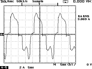
The rectifiers are connected to a 10 kV common bus with two groups of harmonic filters installed. The first group has a 5th and a 7th single tuned harmonic filters. The second group has a 11th and a 13th single-tuned harmonic filters and a 17th high pass harmonic filter. The two rectifiers are connected to the common bus through two 7MVA transformers with a 30 phase shift angle. Such configuration constructs a quasi 12-pulse rectifier system. For the case that two rectifiers have exactly same loading during the operation, harmonic cancellation of the 5th and 7th harmonic currents will be the best. When the loading of the two rectifiers are not equal, for example, 65% load factor for one rectifier and 80% load factor for another rectifier, most 5th, 7th, 17th, and 19th harmonic currents are still cancelled and only small amount of these harmonics are left in the system.Large even harmonic currents were detected at key locations of the system in March 2004. Large 3rd harmonic currents were also found. Such high even harmonics cause serious concerns and an investigation was performed to find out the root cause of the problem.Even harmonics were first detected at the circuit breaker CB3 on the secondary of the 25MVA main service transformer. The measured current waveform at CB3 is shown in Figure. 2. For further verification, another measurement was taken at the circuit breaker CB6, feeding the 10KV common bus, “Rectifier Main Bus”. The measured current waveform at CB6 is shown in Figure. 3. The corresponding harmonic current spectrums at CB3 and CB6 are shown in Figures. 4 and 5, respectively.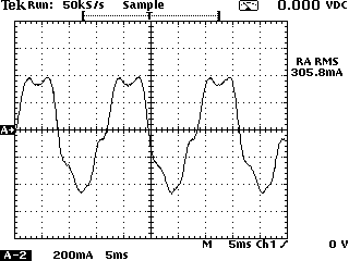 | Figure 2. Current waveform at CB3 on the secondary of the 25MVA main transformer 1 (CT ratio is 3000:1) |
 | Figure 3. Current waveform at CB6, main feeder for two rectifiers (CT ratio is 2000:5) |
Figures. 2 and 3 show seriously distorted current waveforms. The harmonic content shown in Figures 4 and 5 contains large amount of even and 3rd harmonic currents. In order to trace the source of these harmonics, measurements at the inputs of the two rectifiers were taken. The current waveforms for the two rectifiers are shown in Figures. 6 and 7. The corresponding current harmonic spectrums are shown in Figures 8 and 9. | Figure 4. Harmonic current spectrum measured at CB3 |
 | Figure 5. Harmonic current spectrum measured at CB6 |
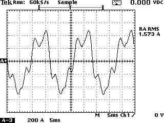
 | Figure 6. Current waveform at CB7 at the input of Rectifier 1 (CT ratio is 600:5) |
 | Figure 7. Current waveform at CB8 at the input of Rectifier 2 (CT ratio is 600:5) |
 | Figure 8. Harmonic current spectrum measured at CB7 at Rectifier 1 |
 | Figure 9. Harmonic current spectrum measured at CB8 at Rectifier 2 |
Due to large amount of the 2nd, 3rd and 4th harmonic currents as shown in Figures. 8 and 9, the current waveforms at the two rectifiers in Figures. 6 and 7 do not show the typical current waveform shape of 6-pulse rectifiers. For the comparison purposes dominant harmonic currents at key measurement points are summarized in Table 3. Dominant harmonic currents measured at the two rectifiers in April 2002 are also included in the same table.| Table 3. Measured harmonic current spectrums in March 2004 and April 2002 at Key location of the facility. |
| | Harmonic order | Harmonic current in percent of the fundamental, % | | March 2004 | April 2002 | | CB 7 Recti-fier 1 | CB8 – Rectifier 2 | CB3 – Secondary main TX | CB6 – Feeder to Rectifiers | Rectifier 1 or 2 | | 2 | 16.8 | 34.3 | 7.0 | 12.2 | 6 | | 3 | 4.8 | 17.2 | 6.9 | 11.7 | 1.8 | | 4 | 8.1 | 6.9 | 15.4 | 26.9 | 2.3 | | 5 | 24.8 | 17.1 | 2.1 | 1.8 | 29.1 | | 6 | 4.1 | 6.0 | 5.3 | 10.9 | 1.0 | | 7 | 9.1 | 8.7 | 1.0 | 2.1 | 2.3 | | 8 | 1.8 | 3.7 | 1.5 | 2.5 | 1.4 | | 9 | 1.8 | 0.9 | 0.5 | 1.2 | 0.5 | | 10 | 1.4 | 3.4 | 0.3 | 0.4 | 1.1 | | 11 | 6.5 | 2.8 | 0.1 | 0.5 | 4.9 | | 12 | 0.8 | 1.1 | 0.1 | 0.2 | 0.1 |
|
|
Table 3 indicates that 16.8% and 34.3% 2nd harmonic currents in percent of the fundamental were generated by Rectifiers 1 and 2 in March 2004, respectively. The 4th harmonic currents are the second largest even harmonics present in the amount of 8.1% and 6.9% of the fundamental for Rectifiers 1 and 2. The two rectifiers also generated large 3rd harmonic currents in the amount of 4.8% and 17.2% of the fundamental. The 3rd harmonic currents will be discussed separately in the next section for Case 1.Characteristic and non-characteristic harmonic currents were flowing upstream of the rectifiers. They first went through CB6, the main feeder of the two rectifiers, then distributed to other parts of the distribution system. Some characteristic harmonics such as the 5th harmonic currents met at the common bus, “Rectifier main bus”, and most of them were cancelled due to the phase shifting of the two transformers. As shown in Table 3, the 5th harmonic current is 24.8% at Rectifier 1 and 17.1% at Rectifier 2, most of the 5th harmonic currents are cancelled at the Rectifier main bus, and the 5th harmonic current remains only 1.8% at CB6.As per the non-characteristic harmonics, the 2nd harmonic current is reduced to 12.2% of the fundamental at CB6 from originally 16.8% and 34.3%, which is reduced. However, the 4th harmonic current increases to 26.9% of the fundamental from originally 8.1% and 6.9%. Similarly, the amplified 4th harmonic current, 15.4% of the fundamental, is also found at CB3. The cause of the amplification of the 4th harmonic current at the upstream electrical circuit is investigated by performing the harmonic and resonance study.A resonance analysis indicates that due to the connection of the two groups of harmonic filters, the peak impedance points created are located at the 4th harmonic frequency (240Hz for the 60Hz system). Since the rectifiers generated a significant amount of even harmonic currents, serious resonance and amplification took place and resulted in large 4th harmonic currents flowing in the system. The system frequency response characteristics at the 10 kV “Rectifier Main Bus” are shown in Figure. 10. The frequency response characteristic curve at 10 kV “Main Bus” connected to the secondary of 25MVA transformer is very similar to Figure. 10.Figure. 10 indicates due to the connection of the 5th, 7th, 11th, and 13th single-tuned harmonic filters a few that the peak impedance points located at 240Hz, 360Hz, 480Hz and 720Hz are created. For a 60Hz system, these frequencies correspond to the 4th, 6th, 8th and 12th harmonics. Peak impedance points are also known as resonance points. The 4th and 6th harmonic currents in Table 3 are significantly increased at CB6, this is the result of the harmonic resonance. The 8th and 12th harmonic currents in Table 3 do not show obvious amplification at CB6 because the inductance of the two 7MVA transformers at the rectifiers branches block part of these higher order even harmonic currents going through to the upstream system.The harmonic current spectrum taken at one of the rectifiers in April 2002 shows the harmonic content of the rectifiers under normal operating conditions (Table 3). It is found that non-characteristic harmonics including the 2nd, 3rd, 4th, 6th etc were very small at that time.The analysis indicates that the two rectifiers generate large amount of non-characteristics harmonics. The non-characteristic harmonic currents in the 4th and 6th harmonic frequencies are amplified due to parallel resonance in the system. That is the reason that a 26.9% 4th harmonic current was detected at the 10 kV “Rectifier Main Bus”, CB6. It is very likely that a malfunction on the rectifiers caused the non-characteristic harmonics problem.Subsequent troubleshooting of the rectifiers verifies that a malfunction on the rectifiers caused this problem. The malfunction was corrected, the large amount ofnon-characteristic harmonic currents disappeared from the system.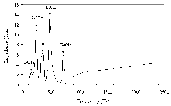 | Figure 10. Frequency response characteristic at 10KV “Rectifier Main Bus” |
4. Case 1: Third Harmonics
Large amounts of 3rd harmonics were also found in Case 1 during the malfunction of the rectifiers in March 2004 (Table 3). The worst case was at Rectifier 2 with 17.2% of 3rd harmonic current. The 3rd harmonic current also appeared in the upstream circuit at CB 6 and CB 3.References[8,9] provide the explanation that under the conditions of utility voltage unbalance, triplen harmonics such as the 3rd and 9th harmonic current can appear at the converters or rectifiers. Two examples are given in[9] with different line voltage unbalance conditions using a 460V 30kVA VFD. The 3rd harmonic currents in percent of the fundamental are 19.2% and 83.7% corresponding to 0.3% and 3.75% line voltage unbalance, respectively. For the case that there is no obvious line voltage unbalance, the 3rd harmonic current is 2.1% for the same drive[9].Based on the same principle, the 3rd harmonic currents shown at the rectifiers in the mining facility in March 2004 were also caused by line voltage unbalance. The three phase-to-phase voltages at CB 8 for Rectifier 2 were measured for 6 hours with one measurement point every minute on March 17 2004. The line voltage unbalance is calculated for each measurement point. The voltage unbalance calculation method is based on an equation provided in[4]. According to[4] the voltage unbalance in percent is defined by the National Electrical Manufacturers Association (NEMA) in Standards Publication no. MG 1-1993 as follows: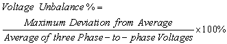 | (4) |
Note that the line voltages are used in this NEMA standard as opposed to the phase voltages. When phase voltages are used, the phase angle unbalance is not reflected in the % Unbalance and therefore phase voltages are seldom used to calculate voltage unbalance[4].The calculated line voltage unbalance during the 6 hour trending measurement is shown in Figure. 11. Figure. 11 indicates that the voltage unbalance at Rectifier 2 for the measurement period ranges between 0.4% and 0.7% with most of the values falling between 0.5% and 0.6%. The calculated line voltage unbalance values explain why the 3rd harmonic current was as high as 17.2% at Rectifier 2.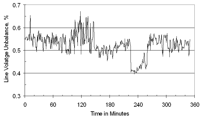 | Figure 11. Calculated line voltage unbalance at CB8, Rectifier 2 based on measured three-phase line-to-line voltages for Case 1 |
5. Case 2: Triplen Harmonics
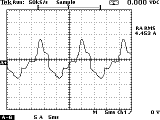
Case 2 addresses a triplen harmonic issue in an oil field distribution system with multiple variable frequency drives (VFD) in operation. The current waveforms at the inputs of the VFDs are seriously distorted. A root cause analysis was required to find a solution to this problem.As the first step for troubleshooting, measurements were taken at the input of each VFD. The measured current waveform for one of the VFDs is shown in Figure. 12. Other VFDs have similar current waveforms at their inputs. It is found that the two humps are not in the same magnitude for each half cycle in the current waveform.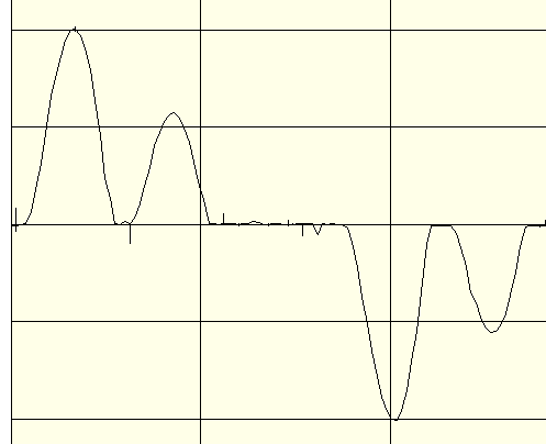 | Figure 12. Measured current waveform at the input of VFD 1 |
The corresponding harmonic current spectrum for the measured current waveform is shown in Figure. 13. This current harmonic spectrum contains 23% 3rd harmonic current and 13% 9th harmonic current in percent of the fundamental. On the other hand, even harmonics are small and all within 1.5%. Therefore, current waveforms distortions are caused by triplen harmonics only.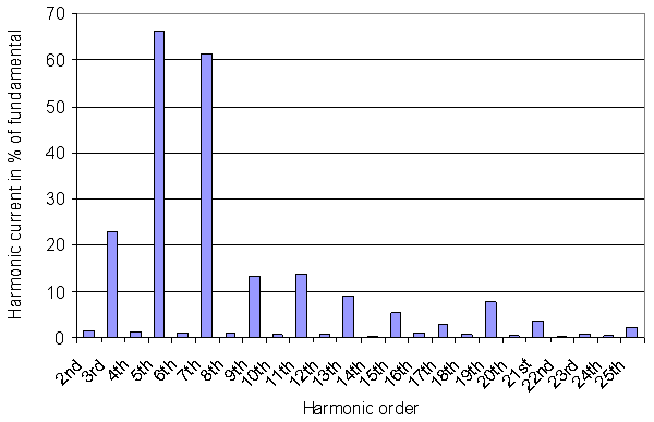 | Figure 13. Harmonic current spectrum at the input of VFD 1 |
Similar to Section 4, the line voltage unbalance for the 480V low voltage system is calculated by using measured three phase-to-phase voltages for VFD1. The measurement trending period is more than 5 days. The calculated line voltage unbalance during the measurement period is shown in Figure. 14. This figure shows that the line voltage unbalance values range between 0.2% and 0.9% with most of the values falling between 0.3% and 0.6%. With such line voltage unbalance from the utility power supply triplen harmonics are generated at the inputs of VFDs and thus further lead to serious current waveform distortions at the drive inputs.Therefore, it can be concluded that the root cause of Case 2 is the voltage unbalance from the utility power supply.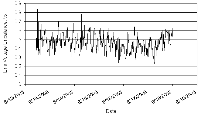 | Figure 14. Calculated line voltage unbalance at the input of VFD1 based on measured three-phase line-to-line voltages for Case 2 |
6. Conclusions
Non-characteristic harmonics including even and triplen harmonics are investigated in this paper. Two case studies are conducted.Case 1 deals with even harmonics generation caused by equipment malfunction of an industrial facility. Even harmonics, particularly the 4th and 6th harmonic currents are significantly amplified by resonance due to the presence of the 5th and 7th single-tuned passive harmonic filters in the system. Case 1 also shows that the root cause for a high 3rd harmonic current (up to 17% at one rectifier), is caused by a supply line voltage unbalance.Case 2 presents a serious current waveform distortion issue in an oil field distribution system with multiple VFDs. Triplen harmonic currents are found at the input of the VFDs, but even harmonic currents appear to be normal. All drives in the system show similar situations. The calculated line voltage unbalance at the input of one VFD ranges between 0.2% and 0.9% based on measured three phase-to-phase voltages. It is concluded that the root cause of Case 2 is line voltage unbalance from the utility power supply.Based on investigations in this study, when significant amount of non-characteristic harmonics appear in industrial facilities, it indicates that something can be seriously wrong in the system. A detailed root cause analysis and troubleshooting should be conducted to identify the root cause of the problem and to resolve it before equipment gets damaged or personnel gets injured.
References
| [1] | IEEE Std 519-1992, “IEEE Recommended Practices and Requirements for Harmonic Control in Electrical Power Systems”, The Institute of Electrical and Electronics Engineers, Inc., ISBN 1-55937-239-7, USA |
| [2] | Vaclav Kus, Zdenek Peroutka, Pavel Drabek, “Non-Characteristic Harmonics and Interharmonics of Power Electronics Converter”, 18th International Conference and Exhibition on Electricity Distribution (CIRED), 2005, PP. 1-5 |
| [3] | M. H. J. Bollen, S. Cundeva, S. K. Rönnberg, M. Wahlberg, Kai Yang, Liangzhong Yao, “A Wind Park Emitting Characteristic and Non-Characteristic Harmonics”, 14th International Power Electronics and Motion Control Conference (EPE/PEMC), 2010, PP. S14-22 - S14-26 |
| [4] | X. N. Yang, M. X. Han, H. Ding, “Non-Characteristic Harmonics Analysis of Double 12-Pulse Series Converters Based on Modulation Theory”, 3rd International Conference on Electric Utility Deregulation and Restructuring and Power Technologies, 2008, PP. 2091-2095 |
| [5] | A. D. Graham, “Non-Characteristic Line Harmonics of PWM AC-DC Converters”, Proceedings of 9th International Conference on Harmonics and Quality of Power, 2000, Vol. 3, PP. 955-960 |
| [6] | A. I. Maswood, Shen Wei, “A Twelve-Pulse Converter under Unbalanced Input Voltage”, the 7th International Power Engineering Conference (IPEC), 2005, Vol. 2, PP. 809-814 |
| [7] | Paul C. Buddinggh, "Even Harmonic Resonance – An Unusual Problem", IEEE Transactions on Industry Applications, Vol. 39, No. 4, July-August 2003, PP. 1181-1186 |
| [8] | Sebastião E. M. de Oliveira and José Octávio R. P. Guimarães, “Effects of Voltage Supply Unbalance on AC Harmonic Current Components Produced by AC/DC Converters”, IEEE Transactions on Power Delivery, Vol. 22, No. 4, October 2007, pp. 2498-2507 |
| [9] | Annette von Jouanne and Basudeb (Ben) Banerjee, “Assessment of Voltage Unbalance”, IEEE Transactions on Power Delivery, Vol. 16, No. 4, October 2001, PP. 782-790 |
| [10] | Seung-Gi Jeong and Ju-Yeop Choi, “Line Current Characteristics of Three-Phase Uncontrolled Rectifiers under Line Voltage Unbalance Condition”, IEEE Transactions on Power Electronics, Vol. 17, No. 6, November 2002, pp. 935-945 |
| [11] | Arshad Mansoor, Jim McGee and Fang Zheng Peng, “Even-Harmonics Concerns at an Industrial Facility Using a Large Number of Half-Controlled Rectifiers”, Proceedings of IEEE 13th Annual Conference Applied Power Electronics Conference and Exposition, 1998, APEC’98, Vol.2, 15-19 Feb 1998, pp. 994-1000 |
| [12] | Ray P. Stratford, “Rectifier Harmonics in Power Systems”, IEEE Transactions on Industry applications, Vol. 1A-16, No.2, March/April 1980, pp. 271-276 |
| [13] | David E. Rice, “Adjustable Speed Drive and Power Rectifier Harmonics - Their Effect on Power Systems”, IEEE Transactions on Industry applications, Vol. 1A-22, No.1, January/February 1986, pp. 161-177 |
 Abstract
 Reference
 Full-Text PDF
 Full-Text HTML