Md Ziaur Rahman1, Mohammed Mynuddin2, Kartik Chandra Debnath3
1Department of Civil Engineering, Dhaka International University, Dhaka, Bangladesh
2Department Electrical and Computer Engineering, Georgia Southern University, Statesboro, GA, USA
3Department of Physics, Govt. Shah E-Tebaria College, Talora, Bogra, Bangladesh
Correspondence to: Md Ziaur Rahman, Department of Civil Engineering, Dhaka International University, Dhaka, Bangladesh.
| Email: |  |
Copyright © 2020 The Author(s). Published by Scientific & Academic Publishing.
This work is licensed under the Creative Commons Attribution International License (CC BY).
http://creativecommons.org/licenses/by/4.0/

Abstract
In this paper, an inset feed rectangular microstrip patch antenna has been designed and simulated at the frequency of 3GHz and the dependency of antenna performance parameters like return loss, VSWR and other antenna parameters have been successfully studied with the variation of the notch gap using CST microwave studio. We have varied the notch width(g) as the proportion of the Length(L), Width(W) of the patch and the width of the microstrip feed line (Wf) to study the performance parameters of patch antenna. FR-4 with dielectric constant of 4.3 is used as a substrate for the designed antenna. The designed rectangular microstrip patch antenna with inset feed technique is very useful for various applications in Industrial, Scientific and Medical sectors which operates at 3GHz range. It shows that the return loss decreases within some certain values of the notch width (g) and after those values the return loss and VSWR started to increase with the corresponding notch gap. Although the return loss and VSWR change with varying the notch gap but no significant changes were observed in case of gain, directivity and bandwidth. The resonant frequency of our designed antenna was almost same with the variation of the notch gap and it remained almost fixed from 2.944 GHz-2.978 GHz.
Keywords:
Inset-fed, Microstrip antenna, Notch width, Return loss, VSWR, Patch antenna, Directivity, CST MWS
Cite this paper: Md Ziaur Rahman, Mohammed Mynuddin, Kartik Chandra Debnath, The Significance of Notch Width on the Performance Parameters of Inset Feed Rectangular Microstrip Patch Antenna, International Journal of Electromagnetics and Applications, Vol. 10 No. 1, 2020, pp. 7-18. doi: 10.5923/j.ijea.20201001.02.
1. Introduction
In recent years the microstrip patch antennas have been used widely used due to their light weight, compact and they are less-expensive [10]. Although the patch antenna has several advantages but it has some limitations like narrow bandwidth [13]. The input impedance of these antennas can be adjusted with their geometrical shapes, dimensions, selecting proper materials and the feed type and the location of the feed. The microstrip patch antenna consists of a small Metallic patch over a large metallic ground layer. A dielectric sheet known as substrate supports the patch. Using printed circuit board technology, the patch is usually etched on the dielectric substrate. That’s why a microstrip patch is also referred to as Printed Antennas. The performance of patch depends on its size and shape. A microstrip patch can be fed either by a microstrip transmission line or co-axial transmission line. The microstrip line can be etched in a single process, together with the patch. A recess in the patch is generated to reach the correct Impedance point on the patch. The recess depth is calibrated to match the impedance. A patch antenna fed with a coaxial transmission line has an input bandwidth of around 2 to 4 percent. A single patch Antenna provides 6-9db for the maximum directive gain. an inherent advantage of patch antenna is its ability to have diversity of polarization. Using multiple feed points or a single feed point with asymmetric patch configurations, patch antennas can be ideally built to have vertical, longitudinal, right hand circular polarization RHCP or left hand circular (LHCP) polarization. The patch normally fed to symmetry around the middle line, thus reducing the excitation of undesirable modes. For improved performance feeding line will have the impedance equal to patch impedance characteristics. A microstrip line [11] was fed to the patch antenna Linked to the point inside of the patch where the impedance to the input is 50Ω. The patch may be square, rectangular, circular, triangle and elliptical but the most commonly used microstrip patch antenna is the rectangular microstrip patch antenna [1]. The basic outline of the antenna is depicted in Figure 1, where W is the width, and L is the length (relative to the feed point) [7]. In the simplest structure, L = W = λeff = 2, which means a constant (εr) of the substance between the patch and the conductive surface (substrate) below which causes the shortening effect. The patch of antenna is a thin metal strip mounted on the ground plane under which the thickness of the metal strip is limited by t << λ0 and the height is restricted by 0.000330 < h < 0.0530 to reduce the fringing effect and analyzed the range of dielectric constants are usually high i.e. in the range of 2.2 < εr < 12 [2-3].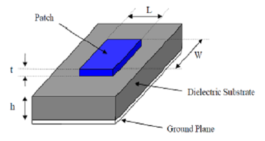 | Figure 1. Basic structure of a microstrip patch antenna |
2. Design Parameters for Patch Antenna
In this paper the proposed rectangular patch antenna has been designed to operate at the frequency of 3 GHz with input impedance of 50Ω using FR4 substrate of dielectric constant 4.3. The most important three parameters considered for constructing a microstrip patch antenna are given below [4]:i) Frequency of operation ((f0): The antenna has been designed between the range of 2-4 GHz and 3.0 GHz is the default resonant frequency exclusive for this research arrangement.ii) Dielectric constant (εr) the substrate: Dielectric constant is one of the most important parameters in the microstrip antenna and substrate is used. Substrate in patch antenna primarily provides the mechanical support of antenna metallization [16]. This support is provided by a substrate with dielectric material which affects the electrical performance of the antenna. One of the most used materials is FR4, but it only supports the 2-4 GHz range. FR4 PCB is also not capable of handling high power at microwave frequencies. Its permittivity is 4.3.iii) Height of dielectric substrate (h): Antennas used in phones are expected to be light in weight and small in size, which restricts their height [16]. By substituting c = 3×10⁸ m/s, εr = 4.3 and f0 = 3.0 GHz, the values of antenna dimensions can easily be determined. The following equations are used in designing the patch antennas [4-5]: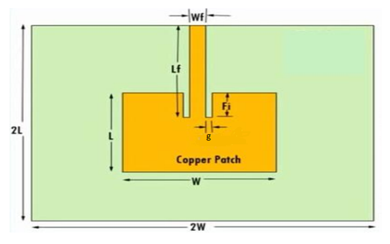 | Figure 2. Inset feed rectangular microstrip patch antenna |
a) Calculation of the width of the patch (W):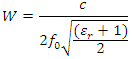 b) Calculation of effective dielectric constant (εreff):
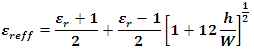 c) Calculation of extension length (ΔL):
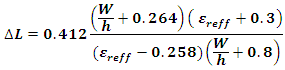 d) Calculation of effective length (Leff):
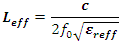 e) Calculation of actual length of patch (L):
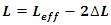 f) Calculation of ground plane dimensions (Lg and Wg):
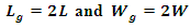 g) Calculation of Length of the Microstrip transmission line [5]:
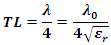 h) Calculation of Inset feed Depth (Fi):The patch antenna has high input impedance at its edge. Impedance falls rapidly if the inset position is moved from edge of the patch towards the center. For providing impedance matching with a 50Ω connector, a curve fit formula for the inset feed depth is expressed as [12]:
 i) Calculation of feed line width (Wf):To obtain 50Ω characteristic impedance, the required feed line width to height ratio
  can be calculated using the formula [14]:
 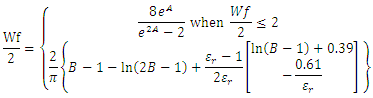 when
when  Where,
 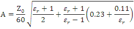 and
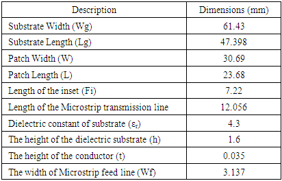
and  To feed microstrip antennas four most popular feeding techniques are used and they are the microstrip line, coaxial probe, aperture coupling and proximity coupling [15]. In our paper we have used the microsrtip inset feed line techniques which is most commonly used and it is very easy to design and use.The dimensions of the antenna design used in this work are shown in Table-1:
Table 1. Design Parameters of the Patch Antenna
 |
| |
|
3. Results and Discussions
In this paper an inset fed rectangular microstrip patch antenna is designed and simulated using CST. This program analyzes the 3D and multilayer configurations in general form. It has been commonly used for the design of different antenna types. It may be used to calculate and plot the return loss, standing wave ratio from Smith charts, Real power Vs Frequency, VSWR, E-field and H-field distribution, gain as well as radiation patterns. The notch width, g was varied in proportion of the length (L) and width (W) of the patch and the width of the microstrip feed line (Wf).
3.1. Performance Parameters with the Variation of g Taken as a Function of Wf
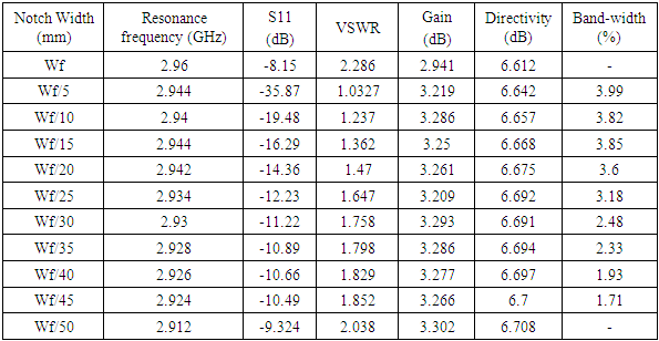
The dependency of the antenna parameters with the variation of g is shown in Table-2. It was observed that by the variation in notch width g the resonant frequency does not shift much and it remains almost fixed at between 2.912 GHz to 2.96 GHz. The input resistance changes rapidly with the position of the feed point and the resonant frequency is somewhat dependant on it [11]. Since the feed position was kept nearly the same of 7.22 mm so the resonant frequency showed negligible change with the variation of the notch width g. When the notch width was taken as Wf the return loss was observed to be -8.15dB. We started to decrease the notch width so that the return loss can be further decreased and it became maximum negative of -35.87 dB at notch width equal to Wf/5 which means the input impedance is matched with the characteristics impedance of the antenna. The bandwidth was calculated using [16] at -10dB of S11 and found maximum of 3.99% at notch width equal to Wf/5. As we decreased the notch width the value of return loss and directivity started to increase again. No significant changes were found in gain while decreasing g from Wf/5. But the directivity was somewhat increased from 6.612dB to 6.708dB with decreasing the value of g. One of the significant changes was found in VSWR. When the S11 was greater than -10dB then the value of VSWR was greater than 2 and it was found the least of 1.0327 when S11 was maximum negative at notch width equal to Wf/5. Again with increasing g its value started to further increase. Fig-3 to fig-8 shows various characteristics of the designed antenna at resonant frequency 9.44 GHz. The radiation pattern at g equal to Wf/5 is shown in fig-6. Fig-7 shows that the field energy decreases with decreasing the value of g taken as the proportion of Wf. The accepted power were high when g was taken equal to W/5 and after that its value started to decrease with increasing or decreasing g as shown in fig-8.Table 2. Performance Parameters with the Variation of g Taken as the Function of Wf
 |
| |
|
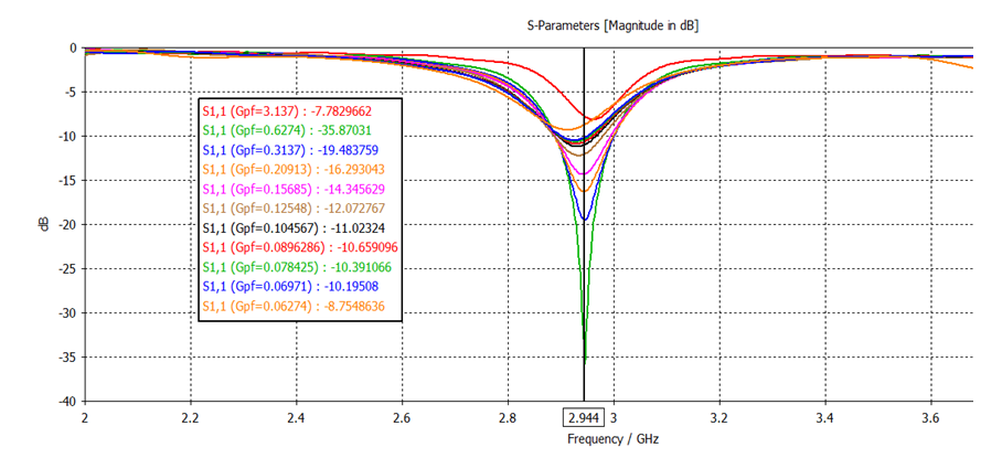 | Figure 3. The return loss, S11 of the designed at resonant frequency 2.944 GHz varying g in proportion of Wf |
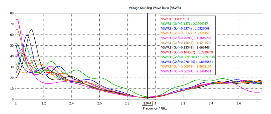 | Figure 4. VSWR of the designed antenna at resonant frequency 2.944 GHz with varying g in proportion of Wf |
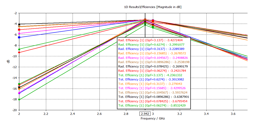 | Figure 5. Efficiencies of the antenna at resonant frequency 2.942 GHz with varying g in proportion of Wf |
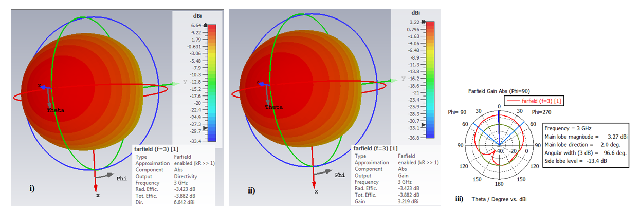 | Figure 6. i) Directivity ii) gain and iii) farfield gain of the designed antenna at resonant frequency 2.944 GHz |
 | Figure 7. Field energy of the designed antenna with varying g in proportion of Wf |
 | Figure 8. Accepted power of the designed antenna at resonant frequency 2.944 GHz with varying g in proportion of Wf |
3.2. Performance Parameters with the Variation of g Taken as a Function of the Length of the Patch (L)
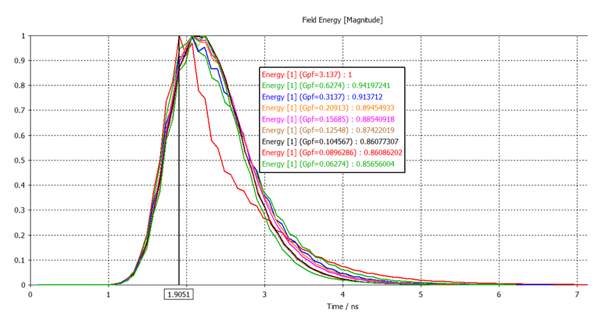
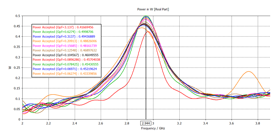
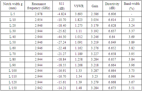
Table-3 shows the antenna parameters of our designed antenna where the notch width g was varied with the proportion of the length (L) of patch. It was observed that when the notch width g was taken equal to L/5 then both the return loss S11 and VSWR were -4.824dB and 3.693 respectively which are very high. Fig-9 to fig-14 show how the return loss S11, VSWR and other parameters were changed with varying the value of notch width g. With decreasing the value of g between L/5 to L/40 as shown in table-3, the S11 and VSWR started to decease. The directivity started remains almost the same with decreasing g and its value was between 6.606dB to 6.673 dB. For the notch width equal to L/40 it is seen that the return loss is of maximum negative -44.303dB and VSWR is the lowest amount of 1.012 as it is related to S11. When the notch width was further decreased then both the return loss and VSWR again started to increase. The resonant frequency does not shift much. It remains almost fixed at between 2.942GHz to 2.978 GHz. Although the bandwidth and gain showed negligible change but the field energy shown in fig-12 started to decrease with the variation of the notch gap g. Fig-14 shows that the accepted power initially started to increase when g was varied within L/5 to L/40 and after attaining its maximum value of 0.4999…W it again started to decrease with the decreased value of g.Table 3. Performance Parameters with the Variation of g Taken as a Function of the Length (L) of the Patch
 |
| |
|
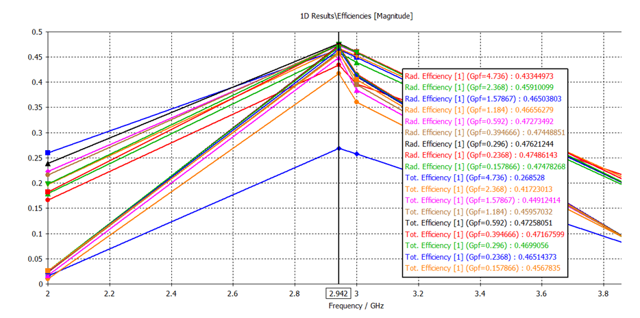 | Figure 9. Efficiencies at resonant frequency 2.944 GHz with varying g with the proportion of L (mm) |
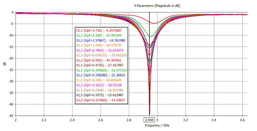 | Figure 10. The return loss, S11 of the designed antenna at resonant frequency 2.944 GHz when g was varied as the proportion of L (mm) |
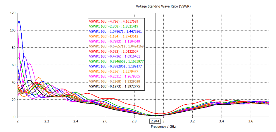 | Figure 11. VSWR of the designed antenna at resonant frequency 2.944 GHz when g was varied as the proportion of L (mm) |
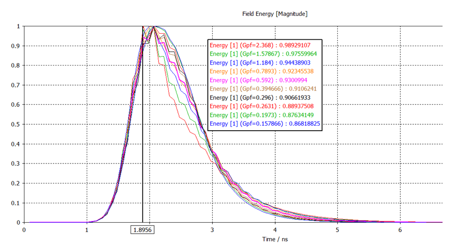 | Figure 12. Field energy when g was varied as the proportion of L (mm) |
 | Figure 13. Outgoing power of the antenna at resonant frequency 2.944 GHz when g was varied as the proportion of L (mm) |
 | Figure 14. Accepted power of the designed antenna at resonant frequency 2.944 GHz with varying g in proportion of L (mm) |
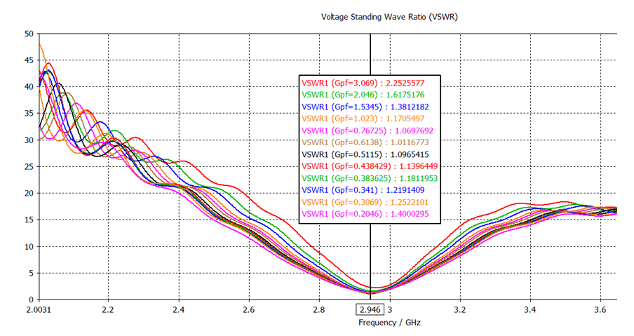 | Figure 15. VSWR of the designed antenna at resonant frequency 2.946 GHz with varying g in proportion of W (mm) |
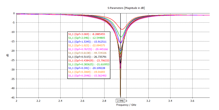 | Figure 16. The return loss, S11 of the designed at resonant frequency 2.946 GHz when g was varied as the proportion of W (mm) |
3.3. Performance Parameters with the Variation of g Taken as a Function of the Width (W) of the Patch
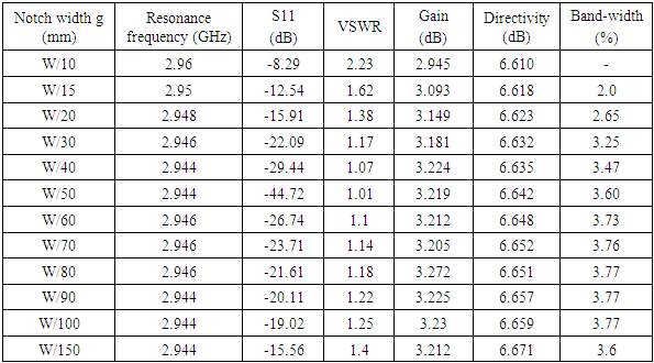
Table-4 shows the performance parameters of our designed antenna where the notch width g was varied in proportion to the width (W) of the patch. It was observed that at the notch width g equal to W/10 both the return loss S11 and VSWR were -8.29dB and 2.23 respectively that are not acceptable according to [16]. With decreasing the value of g as the proportion of W shown in table-4, both the S11 and VSWR started to decease but the directivity started to increase a little bit and its value was between 6.610dB to 6.671 dB. When the notch width was taken equal to W/50 it was seen that the return loss was maximum negative of -44.72 dB since the input impedance was perfectly matched than the above other two cases and VSWR attained its minimum of 1.012. When the notch width was further decreased from W/50 both the return loss and VSWR again started to increase. The resonant frequency does not shift much with varying g due to the same feed position of the transmission line. While the bandwidth showed little increases with the variation of the notch gap g but no significant change was observed in gain. The radiated power and the accepted power also increased when g was varied among W/10 to W/50. Further varying g from W/50 both radiated and accepted power started to decrease. Fig-15 to fig-22 shows the various characteristics of the designed antenna with the variation of g taking as the proportion of the width (W) of the patch.Table 4. Performance Parameters with the Variation of g Taken as the Function of the Width (W) of the Patch
 |
| |
|
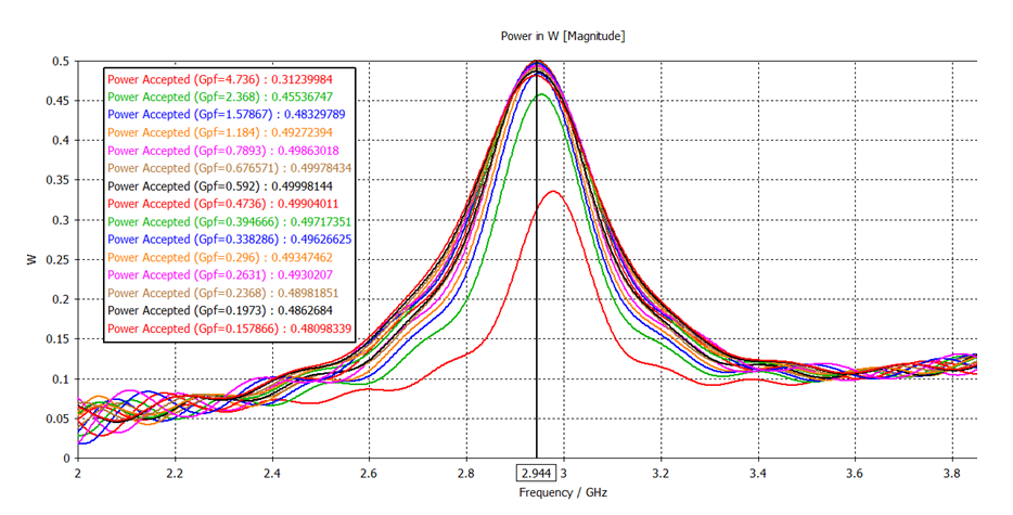
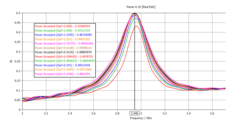 | Figure 17. Accepted power at resonant frequency 2.946 GHz when g was varied width the proportion of W (mm) |
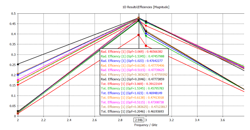 | Figure 18. Efficiencies at resonant frequency 2.946 GHz when g was varied as the proportion of W (mm) |
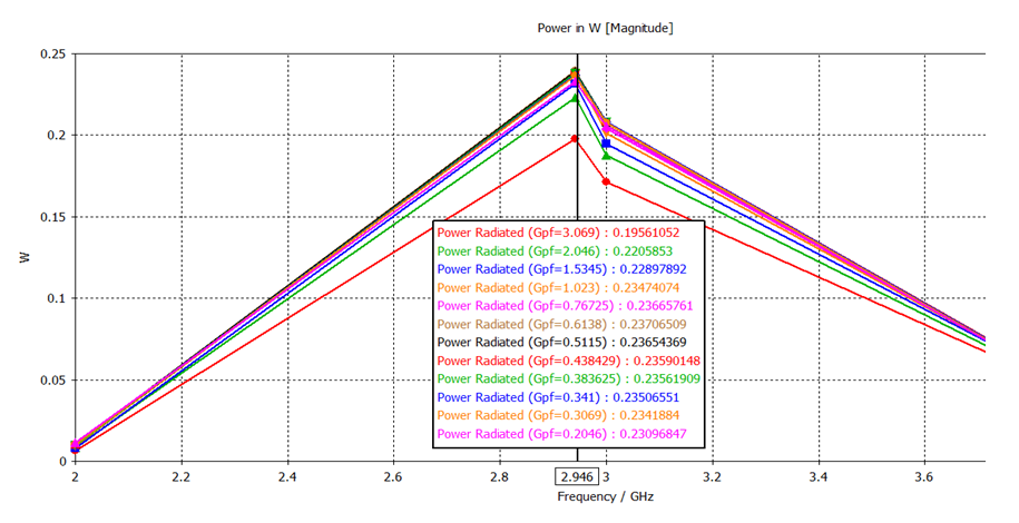 | Figure 19. Radiated power at resonant frequency 2.946 GHz when g was varied as the proportion of W (mm) |
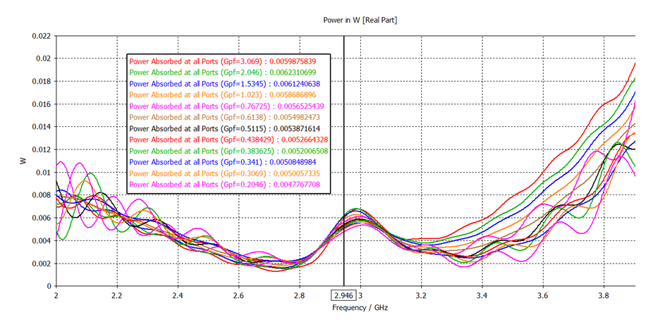 | Figure 20. Power absorbed at all ports at resonant frequency 2.946 GHz when g was varied as the proportion of W (mm) |
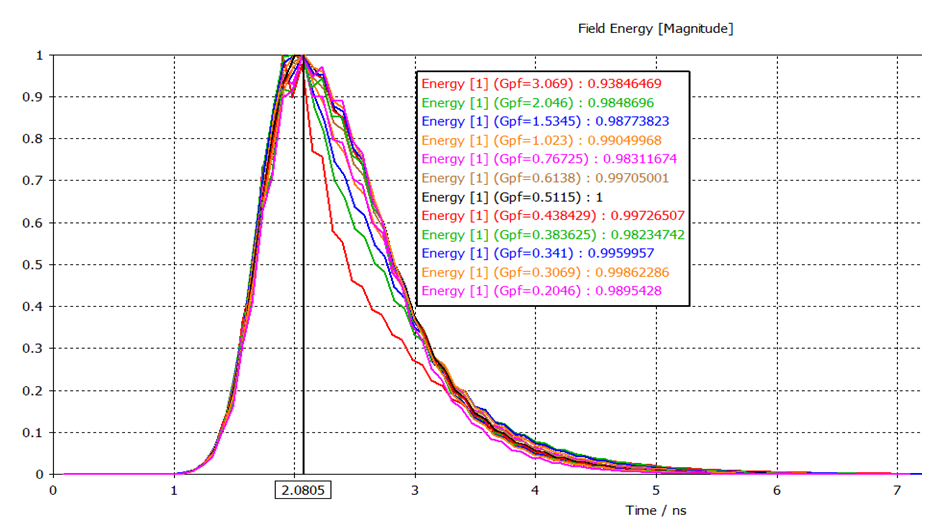 | Figure 21. Field energy when g was varied as the proportion of W (mm) |
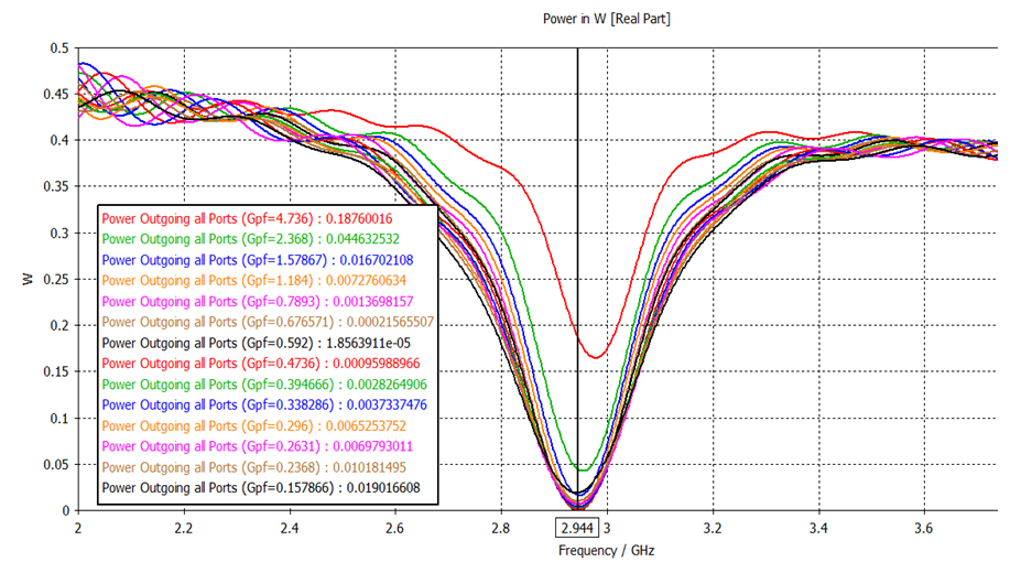
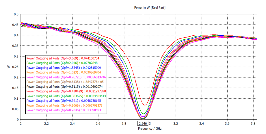 | Figure 22. Outgoing power of the antenna at resonant frequency 2.946 GHz when g was varied as the proportion of W (mm) |
4. Conclusions
In this paper an inset fed rectangular microstrip patch antenna has been designed and simulated for the analysis of antenna parameters. The dependency of return loss, VSWR, directivity, gain and bandwidth on notch width has been studied and the corresponding results have been simulated for 50Ω microstrip line. For the notch width g taken as the proportion of Length (L), Width (W) and Wf both return loss, VSWR decreases within a limit and after those values of g it starts to increase again. When return loss S11 was maximum negative then the VSWR showed the minimum value. Also varying g above or below this value of g at which maximum negative S11 is obtained, the field energy decreases gradually. For the variation of g in all three cases, the bandwidth and gain showed negligible change but the directivity showed little increase with decreasing the value of g. The return loss S11 and VSWR started to decrease when g was varied within the limit Wf to Wf/5, L/5 to L/40 and W/10 to W/50. When the notch width g was further decreased then the return loss S11 and VSWR started to increase again. Hence it can be concluded that there is a range in which if notch width g is varied, the return loss and VSWR first decreases with increasing g and after attaining its minimum value, the return loss and VSWR again start to increase. Also there is a relationship among accepted & radiated power and field energy as it increase or decrease with the variation of g.
References
| [1] | Harish, A. R. Sachidananda, M. “Antenna Theory and Wave Propagation,” ISBN: 978‐0‐19‐568666‐1. |
| [2] | P. Subbulakshmi and R. Rajkumar, “Design and Characterization of Corporate Feed Rectangular Microstrip Patch Array Antenna”, IEEE International Conference on Emerging Trends in Computing Communication and Nanotechnology, 2013. |
| [3] | Md. Tanvir Ishtaiqueul Huque, Md. Kamal Hosain, Md. Shihabul Islam and Md. Al-Amin Chowdhury, “Design and Performance Analysis of Microstrip Array Antennas with Optimum Parameters for X-band Applications,” International Journal of Advanced Computer Science and Applications, Vol. 2, No. 4, 2011. |
| [4] | “Comparison of Performance Characteristics of Rectangular, Square and Hexagonal Microstrip Patch Antennas,” DOI: 10.1109/ICRITO.2014.7014684. |
| [5] | “International Journal of Engineering Sciences & Emerging Technologies,” ISSN: 2231-6604, Volume 4, Issue 2, Feb. 2013. |
| [6] | “Design and Simulation of Microstrip Rectangular Patch Antenna for Bluetooth Application,” IJLTEMAS ISSN 2278-2540, Volume IV, Issue VIII, August 2015. |
| [7] | “International Journal of Recent Technology and Engineering,” IJRTE, ISSN: 2277-3878, Volume-2, Issue-3, July 2013. |
| [8] | Karuna Kumari, Prof. P. V. Sridevi, “Design and Analysis of Microstrip Antenna Array Using CST Software,” IJESC, 2321 3361, 2016. |
| [9] | Miss Anjali Majale, and Mrs. S. R. Mahadik “Rectangular Microstrip Patch Antenna for 2.45 GHz Wireless Applications,” IJSRD Vol. 3, Issue 08, 2015. |
| [10] | I. J. BahI and P. Bharta, “Microstrip Antennas,” Artech House, Boston, 1980. |
| [11] | C.A. Balanis, “Antenna Theory Analysis and Design,” Third edition, Wiley, 2005. |
| [12] | https://www.researchgate.net/publication/333292532, DOI:10.13140/RG.2.2.12633.57441. |
| [13] | Kin-Lu Wong, “Compact and Broadband Microstrip Antennas,” Copyright 2002, John Wiley & Sons, inc. |
| [14] | “Characteristics of Patch Antenna with Notch gap Variations for Wi-Fi Applications,” International Journal of Applied Engineering Research, Volume 11, Number 8, 2016. |
| [15] | D. M. Pozar, “Microstrip Antennas,” proc. IEEE, vol. 80, No. 1, Jan 1992. |
| [16] | Rahman Md Z. and Mynuddin Mohammed, “Design and Simulation of High Performance Rectangular Microstrip Patch Antenna Using CST Microwave Studio,” Volume 8, Issue 8, August 2020. |

 Abstract
 Reference
 Full-Text PDF
 Full-text HTML