Htutzaw Hein, Yongjian Li, Shuaichao Yue, He Sun
State Key Laboratory of Reliability and Intelligence of Electrical Equipment, Hebei University of Technology, Tianjin, China
Correspondence to: Yongjian Li, State Key Laboratory of Reliability and Intelligence of Electrical Equipment, Hebei University of Technology, Tianjin, China.
| Email: |  |
Copyright © 2020 The Author(s). Published by Scientific & Academic Publishing.
This work is licensed under the Creative Commons Attribution International License (CC BY).
http://creativecommons.org/licenses/by/4.0/

Abstract
This paper illustrates the core loss analysis for non-grain-oriented silicon steel, grain-oriented silicon steel, and soft magnetic composite (SMC) materials under sinusoidal excitation and Sinusoidal Pulse Width Modulated (SPWM) excitations. The SPWM voltages with their modulation and carrier ratio have been created by MATLAB for experimental verification. The standardized measurement methods: Epstein Frame method and ring sample method, have been used to test the soft magnetic materials. The core losses from different experimental data have been analyzed. The results show that the core losses under three different SPWM excitations depending on the modulation and carrier ratios of PWM waveforms are different from the core losses supplied by sinusoidal excitations. And also, it can be found that the magnetic behavior of the material affects the core loss under non-sinusoidal excitation.
Keywords:
Core losses, Non grain-oriented silicon steel, Grain-oriented silicon steel, SMC material, SPWM
Cite this paper: Htutzaw Hein, Yongjian Li, Shuaichao Yue, He Sun, Core Losses Analysis for Soft Magnetic Materials under SPWM Excitations, International Journal of Electromagnetics and Applications, Vol. 10 No. 1, 2020, pp. 1-6. doi: 10.5923/j.ijea.20201001.01.
1. Introduction
Modern AC motors and electromechanical drives are fed through voltage source inverters (VSI) using sinusoidal pulse width modulation (SPWM) schemes [1]. Particularly, it can be considered as the standard solution when voltage and frequency regulation is required, for control and energy savings [2]. Generally, there are two major losses in electrical drives: copper losses, and core losses. The copper losses are relatively easy to calculate from machine windings. However, the calculation of core losses is much more complex under non-sinusoidal excitation because of the non-linearity of induction waveform and materials behaviour. Many kinds of research have been done for core loss estimation under sinusoidal excitation including empirical method, Steinmetz equation [3]. Unfortunately, there are no international standards for core loss measurement under non-sinusoidal excitation. Expanding the use of the SPWM scheme, the core loss measurement has also become an essential role in electrical drives [2]. The author discussed [4], loss analysis of soft magnetic ring core under SPWM and space vector pulse width modulation (SPVM) by using the ring sample method. However, the flux density waveform and hysteresis loop have not been shown. The unsymmetrical hysteresis loop due to the DC bias condition with PWM excitations has been discussed and introduced to the isolation transformer in the measurement circuit [5]. However, the material behaviour under SPWM with the low modulation and carrier ratios (i.e. M<0.5 and N<0.5) has not been discussed yet.Therefore, the experimental verification of magnetic materials, i.e. non grain-oriented silicon steel (B35A230), cold-rolled grain-oriented silicon steel (30Q120) and Soft Magnetic Composite SMC, has been analysed under SPWM excitations in this paper. The hysteresis loop has also been presented here. Eventually, the core losses under the three different SPWM excitations, with low, middle and high ratios, and sine voltage have been compared for three testing materials. Figure 1 shows the hysteresis loop for three materials under sinusoidal excitation.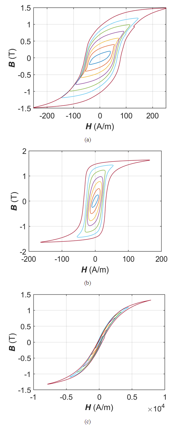 | Figure 1. Hysteresis loop for each soft magnetic material under Sine (50Hz): (a) NO steel (b) GO steel (c) SMC |
2. Sinusoidal Pulse Width Modulation (SPWM)
The SPWM waveform can be generated by comparing one or two sinusoidal reference signals with a triangular carrier wave, and the width of each pulse varied proportionally to the amplitude of a sine wave evaluated at the centre of the same pulse. There are two types of SPWM which are three-level (unipolar) and two-level (bipolar) switching. Two-level SPWM is not widely used because of requiring large filters at the output due to the high harmonics content and the switching losses are more [6]. This measurement takes the three-level SPWM as a sample to signify multi-level SPWM for evaluation. The modulation ratio (M) and carrier wave ratio (N) of SPWM can be defined as: | (1a) |
 | (1b) |
Where Ur is the amplitude of modulation wave, Uc is the amplitude of carrier wave, fr is modulation wave frequency, and fc is carrier wave frequency. For the measurement, three different ratios of three-level SPWM were chosen, and the base frequency is 50Hz and the base amplitude is 1V for sine wave. The three-level SPWM waveforms are generated with the different modulation ratios and carrier wave ratios: low ratio (M=0.2 and N=20), middle ratio (M=0.5 and N=50) and high ratio (M=0.8 and N=80) by using MATLAB Simulink. Three-level SPWM waveforms are illustrated in Figure 2.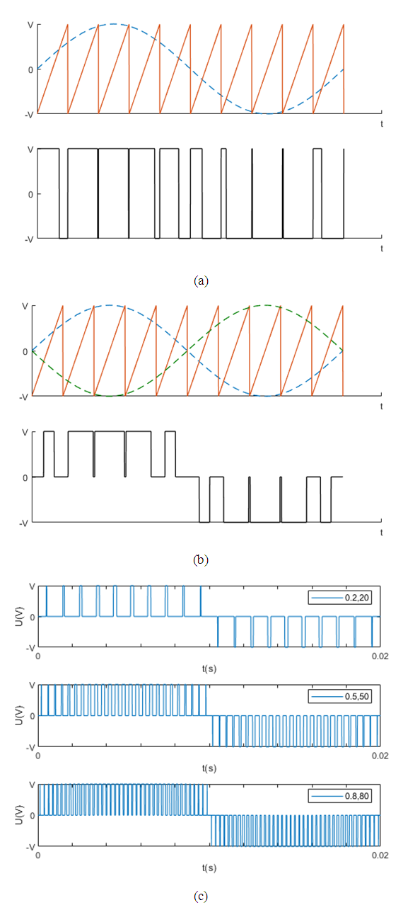 | Figure 2. (a) Two-level SPWM, (b) Three-level SPWM and (c) Three-level SPWM waveforms with low, middle and high ratios by MATLAB Simulink |
3. Measurement Setup and Principle
3.1. Measurement Scheme
Figure 3 illustrates the measurement scheme of this paper. According to the International Standard IEC 60404-2 [7], the measurement circuit consists of a 25cm Epstein frame or ring core sample with the primary and secondary windings. In the Epstein frame unit, each winding is 700 turns uniformly wound. The specimen of 30mm width, 300mm length testing steel sheets have been inserted into the Epstein frame and five sheets for each side. For SMC materials, the primary winding is 316 turns and the secondary winding is 50 turns. The existence of DC components can be reduced in the PWM voltage source by adding a two-ohm resistor in the excitation circuit [5].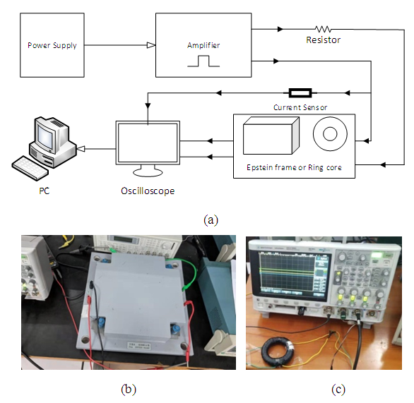 | Figure 3. (a) Scheme of measurement (b) Epstein frame measurement (c) Ring core measurement |
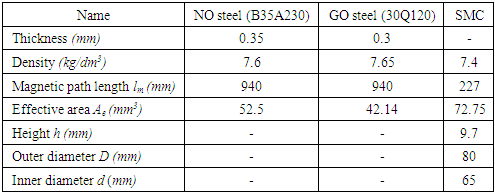
The effective magnetic path length for the 25cm Epstein frame was set to 940mm [7] and the magnetics’ characteristics of the testing materials are shown in table 1.Table 1. The magnetics’ characteristics of the testing materials
 |
| |
|
3.2. Measurement Principle
These SPWM voltages have been created in MATLAB Simulink and changed to the (.tfw) file which can be uploaded to the amplifier by using the manufacture's amplifier software, Arbexpress. The oscilloscope collected the information of primary voltage from the amplifier, the secondary voltage from secondary winding and the current from the current sensor. According to this information, magnetizing force H(t) in the specimen is: | (2) |
Where Np is the number of turns in the primary winding, ip is the current flowing in the primary winding and lm is the mean magnetic path length of the core. The secondary winding is used to measure the magnetic flux density B created by the primary winding current. Average flux density B can be calculated by using: | (3) |
After that, the B-H loops are plotted. Based on the core losses separation model [8], the specific core losses P (in [W/kg]) can be determined by this equation: | (4) |
Where f is the frequency of excitation voltage, and ρfe is the specific mass density of the testing magnetic materials [9]. All these calculation processes can be done in the MATLAB program.
3.3. Core Losses Equation
Traditionally, the Steinmetz equation (SE) method [3], the empirical equation, is mainly adopted to calculate core losses for sinusoidal excitations. Manufacturers also present the core losses in the form of SE such as: | (5) |
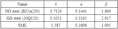
Where Bm is the peak flux amplitude, α is the frequency-dependent and β is the flux density-dependent. These two variables can be obtained by using a curve fitting method with the specific frequency range. Figure 4 shows each core loss under 50Hz frequency Sine waves and table 2 shows the fitting values of α and β for all testing materials. This data has been used to verify the actual measurement results in the next section.Table 2. Fitting parameters at Sine 50Hz
 |
| |
|
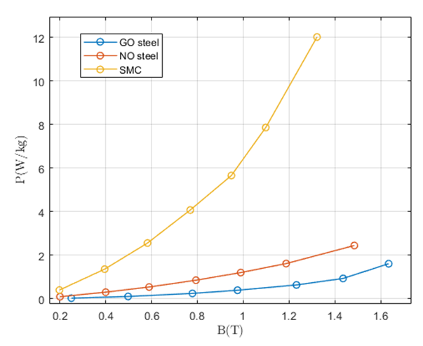 | Figure 4. Core loss for three testing materials at Sine 50Hz |
4. Testing Results and Discussion
Here, the result of the measurement system under SPWM is examined. In SPWM (M=0.2 and N=20), the shape of the hysteresis loop is quite different from (M=0.5 and N=50) and (M=0.8 and N=80), it also happens in B waveform because of the higher harmonic contents in the (M=0.2 and N=20). Figure 5.b shows the results of grain-oriented silicon steel. By comparing it with Figure 5.a, the GO steel’s hysteresis loop is more stable and the flux density B waveform is the same as in Sine excitation. The grains size of NO steel is smaller than the GO steel and the manufacturing process is to obtain the random orientation of grains in order to create fully isotropic material [10]. Due to the anisotropy of GO steels, the magnetic flux can easily get a stationary state without the rotation of grains. Such material is widely used in the transformer's core. In figure 5.c, the hysteresis loop is not a regular shape however, the symmetric hysteresis loop shows that can neglect the DC bias magnetization. If the presence of DC bias is in excitation, it will be corrupted the asymmetric hysteresis loop in this measurement. When the excitation flux is over 1T, the current in primary winding becomes excesses because there are high harmonics content in the SPWM excitation. According to equation (4), the core losses of the three testing materials can be calculated. For the sake of completeness and for comparison, the manufacturer’s core losses equation under sine excitation is shown in this research work. 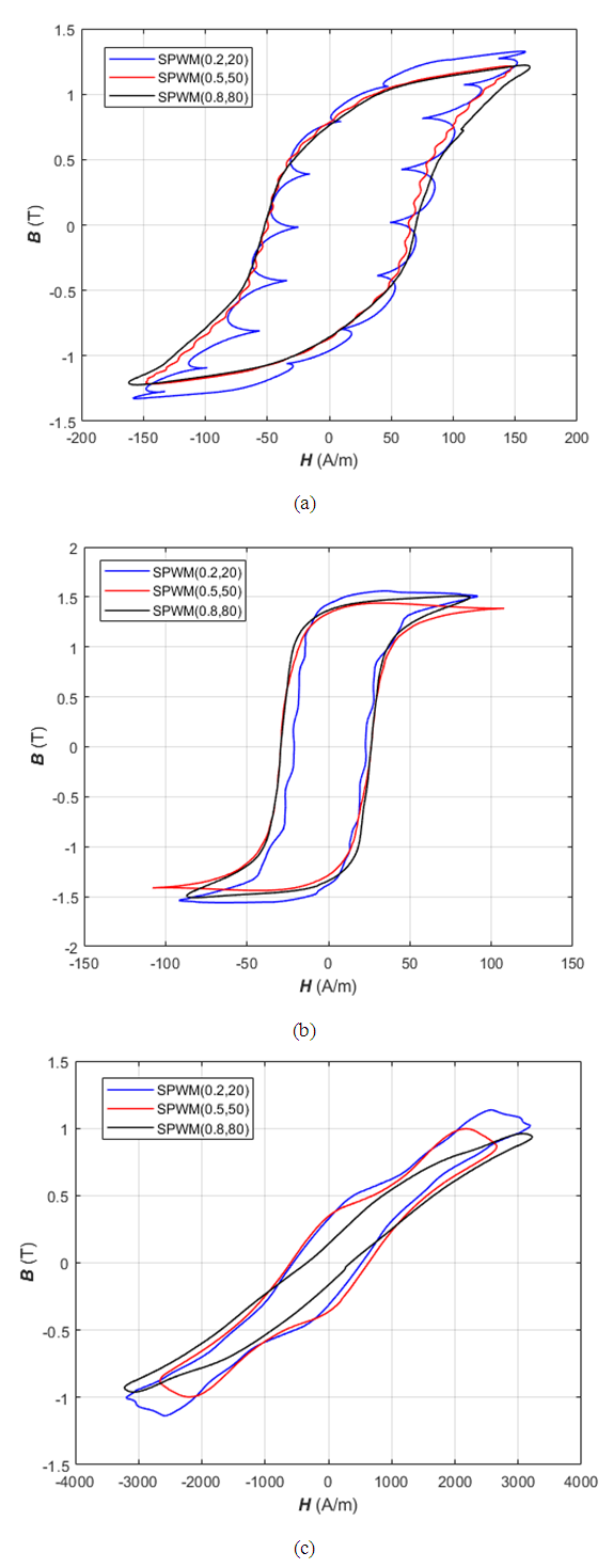 | Figure 5. Hysteresis loop for testing materials under SPWM excitations: (a) NO steel (b) GO steel (c) SMC |
Figure 6 shows each specific core losses P for NO steel, and GO steel by using Epstein frame measurement, and the SMC materials using ring core sample under Sine and SPWM excitations. The measurement results show that the experimental data under Sine excitation are quite similar to the manufacturer data. However, the core losses equation (5) is only valid for the Sinewave [3]. 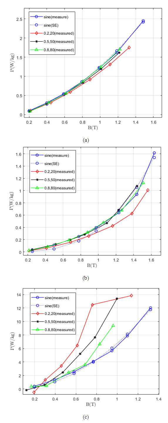 | Figure 6. Each specific core loss P under both Sine and SPWM voltage excitations (a) NO steel, (b) GO steel and (c) SMC |
In NO and GO steels, the core loss under Sine and SPWM are close to each other. On the other hand, the core loss for SMC material with SPWM excitation is more different from Sine excitation and non-linear behavior has shown in a low ratio of SPWM (M=0.2 and N=20) because there are more harmonics contents in SPWM with low ratio than the middle and high ratios. The higher ratio of SPWM has a similarity with the Sine wave and core losses are slightly equal. Comparing these two steel measurements, the core loss of NO steel is much higher than the GO steel. Because the non-grain-oriented steel has isotropic properties and cost considerations, it is useful especially in the motor but the grain-oriented steel has anisotropic properties, costly, low core losses and high magnetic permeability [11]. That kind of steel is used especially in transformers in transformers. In fact, the core loss difference of grain-oriented and non-grain-oriented steels cannot be easily assessed. It can be found that there are many factors such as thickness, permeability, and domain size of the material that influenced the core loss difference. The soft magnetic composite (SMC) material is made by the iron particle and it is insulated by coating. It has low eddy current loss, high saturation flux and low-cost mass production due to the powder metallurgy method which is a cost-effective method for producing a high volume of consistent parts [12]. Generally, silicon steel has a better performance than the SMC at low frequency. On the other hand, the soft magnetic composite material has lower losses than the electrical steels at high frequency. The main advantage of SMC is that it can get complex shapes for various designs. Choosing the right material for a specific design is the essential work for the design engineers.
5. Conclusions
In this work, the core loss for non-grain-oriented steel, grain-oriented steel and soft magnetic composite material with sine and sinusoidal pulse width modulated excitations have been discussed. The hysteresis loop of three materials under SPWM excitations have also been presented. According to the experimental data, silicon steel has good performance at low frequency, especially in grain-oriented steel. However, the excitation frequency 50Hz is the low-frequency range for SMC material and it cannot get better performance than the silicon steel Isotropic and anisotropic properties of the magnetic material are also an important role for machine designers. Low modulation and carrier ratio of SPWM can cause more core loss because of higher harmonics content. It is sure that the core loss measurement under the PWM scheme plays an important role in the electrical industry.
ACKNOWLEDGEMENTS
This work was supported in part by the National Natural Science Foundation of China, (No. 51777055, 51690181), National Key R & D Program of China (2017YFB0903904), Hebei Province Science Foundation for Distinguished Young Scholars (No. E2018202284), and Program for Hundred Excellent Innovative Talents of Hebei Province (No. SRLC2017031).
References
| [1] | Z. Sun, J. Shen, M. Jin and H. Hao, "Research of the influence of different PWM inverters on the iron losses for induction motors," 2014 17th International Conference on Electrical Machines and Systems (ICEMS), Hangzhou, 2014, pp. 96-100. doi: 10.1109/ICEMS.2014.7013461. |
| [2] | A. Boglietti, A. Cavagnino, T. L. Mthombeni and P. Pillay, “Comparison of lamination iron losses supplied by PWM voltages: US and European experiences,” IEEE International Conference on Electric Machines and Drives, 2005., San Antonio, TX, 2005, pp. 1431-1436. doi: 10.1109/IEMDC.2005.195909. |
| [3] | C.P. Steinmetz, “On the law of hysteresis (part ii.) and other phenomena of the magnetic circuit,” Transactions of the American Institute of Electrical Engineers, vol. IX, no. 1, pp. 619–758, Jan. 1892. |
| [4] | H. Gao, Y. Li, S. Wang, J. Zhu, Q. Yang, C. Zhang, and J. Li, “Losses analysis of soft magnetic ring core under sinusoidal pulse width modulation (SPWM) and space vector pulse width modulation (SVPWM) excitations,” AIP Advances, vol. 8, no. 5, pp. 056638-1-056638-5, May 2018. |
| [5] | C. Junquan, M. Weiming, W. Dong, Y. Xiwen and G. Yunjun, “Development of automatic iron loss measurement system of magnetic material with PWM excitation,” 2011 International Conference on Materials for Renewable Energy & Environment, Shanghai, pp.1013-1017, 2011, doi: 10.1109/ICMREE.2011.5930973. |
| [6] | S. Rajendran, “Chapter 5, Modified Sinusoidal Pulse Width Modulation (SPWM) Technique Based Controller,” pp. 74-79, 2014. |
| [7] | Magnetic materials - Part 2: Methods of measurement of the magneticproperties of electrical steel sheet and strip by means of an Epstein frame,” pp. 9-29, IEC 60404-2: 1996. |
| [8] | H. Hein, S. Yue, and Y. Li, “Comparative Core Loss Calculation Methods for Magnetic Materials under Harmonics Effect,” IOP Conference Series: Materials Science and Engineering, vol. 486, p. 012019, Jul. 2019. |
| [9] | F. Fiorillo and A. Novikov, "An improved approach to power losses in magnetic laminations under nonsinusoidal induction waveform," in IEEE Transactions on Magnetics, vol. 26, no. 5, pp. 2904-2910, Sept. 1990. doi: 10.1109/20.104905. |
| [10] | S. Zurek, “Characterisation of Soft Magnetic Materials Under Rotational Magnetisation,” Chapter 1. Introduction, pp. 22-28, Nov. 2017. |
| [11] | M. Soinski et al., “Anisotropy in iron-based soft magnetic materials,” in: K. Buschow (ed.), Handbook of Magnetic Materials, Chapter 4, North-Holland, p. 347, 1995. |
| [12] | Y. Guo, J. Zhu, H. Lu, Z. Lin and Y. Li, "Core Loss Calculation for Soft Magnetic Composite Electrical Machines," in IEEE Transactions on Magnetics, vol. 48, no. 11, pp. 3112-3115, Nov. 2012. doi: 10.1109/TMAG.2012.2197677. |

 Abstract
 Reference
 Full-Text PDF
 Full-text HTML