International Journal of Electromagnetics and Applications

p-ISSN: 2168-5037    e-ISSN: 2168-5045

2019;  9(1): 7-13

doi:10.5923/j.ijea.20190901.02


State of the Art Techniques for Cognitive Radio Antenna Design

Oluwafemi A. Ilesanmi1, Charles U. Ndujiuba1, Olabode Idowu-Bismark1, Oluseun Oyeleke Wikiman2, Sadiq Thomas2, Idris Muhammad3

1Electrical and Information Engineering Department, Covenant University, Ota, Nigeria

2Dept of Computer Engineering, Nile University, FCT, Abuja, Nigeria

3Electrical Department, Nuhu Bamalli Polytechnic, Zaria, Nigeria

Correspondence to: Oluwafemi A. Ilesanmi, Electrical and Information Engineering Department, Covenant University, Ota, Nigeria.

Email:

Copyright © 2019 The Author(s). Published by Scientific & Academic Publishing.

This work is licensed under the Creative Commons Attribution International License (CC BY).
http://creativecommons.org/licenses/by/4.0/

Abstract

In this letter, a survey of different recent state of the art techniques that have been deployed in the design of antennas that can perform excellently for cognitive radio application is carried out. Cognitive radio system fundamentals and antenna requirements for its smooth operations are also discussed. The performance of the antennas designed by various techniques in terms of, the radiation pattern, VSWR/Return loss, peak gain, radiation efficiency are discussed. Issues relating to the design techniques and some factors to consider when designing a suitable antenna for cognitive radio system also highlighted.

Keywords: Cognitive Radio, Frequency Reconfigurable, UWB Antenna, Narrow band Antenna

Cite this paper: Oluwafemi A. Ilesanmi, Charles U. Ndujiuba, Olabode Idowu-Bismark, Oluseun Oyeleke Wikiman, Sadiq Thomas, Idris Muhammad, State of the Art Techniques for Cognitive Radio Antenna Design, International Journal of Electromagnetics and Applications, Vol. 9 No. 1, 2019, pp. 7-13. doi: 10.5923/j.ijea.20190901.02.

1. Introduction

Cognitive radio is an intelligent radio system that has the ability to monitor its environment and based on its idea of sensing and learning from its environment accordingly changes its mode of operation in order to maintain a good quality of service [1]. This will ensure that the system operates in the most suitable mode to achieve power and spectral efficiency under various RF conditions [2, 3]. Cognitive radio system is aimed at ensuring a highly reliable communication and efficient usage of the limited radio spectrum while eliminating overcrowding of some part of the spectrum and underutilization of some by implementing a dynamic spectrum access scheme (DSA). Although there are lot of parameters like: modulation, transmit-power, carrier-frequency, polarization, radiation pattern, that the cognitive radio can change according to the idea of learning and understanding of its environment, but the key parameter requiring changes for cognitive radio system is the operating frequency [1]. This therefore necessitated the need for a reconfigurable antenna.
Antenna, been an important component of a cognitive radio system has attracted a lot of interest from researchers both from the academics and the industries because of its complexity. In a cognitive-radio environment, there are two types of users: primary users and secondary users [4, 5]. The primary users have some part of the spectrum or channel already assigned to on a permanent basis and so have the right to freely access it at any point in time. Since primary users are not active all the time, a cognitive-radio system, designed for a more efficient use of spectrum should be able to dynamically assign the free part of the channel to the secondary users. So the antenna used in cognitive radio environment is expected to operate in two states, sensing state and communicating state.
Cognitive radio system can operate in two modes, the underlay and the interleave mode [5] depending on the interference tolerant level of the primary users. In the underlay mode, only one UWB antenna with reconfigurable frequency capability is used for sensing the wide spectrum and at the same time for continuous communication since communication in this mode is performed below the noise floor of the primary users, with restriction on their transmission power, which is limited to -40dBm/MHz to avoid interference with the primary users [6]. In the interleave mode, the secondary users can transmit at full power, but only over the white space i.e. over channels that are not currently used by the primary users. The restriction here is on when and where the secondary users can transmit. Therefore, for an antenna to work perfectly well for cognitive radio system, it must be capable of sensing a wide range of frequency and also reconfigure its operating frequency. This paper is arranged as follows: Section I is introduction, section II is a brief description of Antennas for cognitive radio system, section III highlights some of the recent techniques employed in the design of cognitive radio antenna and section IV is the conclusion.

2. Cognitive Radio Antenna

Cognitive radio system needs a specialized antenna for spectrum sensing and communication. This can be designed in two ways: One, integrating a narrow band antenna into a UWB antenna, where the UWB antenna does the spectrum sensing and the narrow the communication. Secondly, only one UWB antenna can be used to perform both spectrum sensing and communication with the capability of frequency notching and re-configurability. In most of the reported designs, microstrip antenna, planar monopole and slot antennas have been mostly used. For any antenna to be suitable for cognitive radio system, frequency re-configurability is an essential characteristic of such antennas.
Basic microstrip antenna design starts from the basic transmission line model as stated in [7, 8]. Since the antenna is expected to cover the UWB range of frequency, the center frequency can be chosen to be 6.85 GHz. These designs mainly involve the design of a conventional antenna whose shape is then modified to achieve the desired objective. This may involve different modifications to the radiating element, the ground plane and the feed structure with parametric optimization to achieve the best result. These modifications such as introducing slots, defected ground, increase substrate height and low dielectric substrate are in a way to increase the impedance bandwidth of the antenna whiles switches are also incorporated to make the antenna frequency tunable. The re-configurability of the antenna makes it suitable for cognitive radio application. Reconfiguration in antennas can be achieved by using electronic switches to alter the effective length of the antenna [9, 10].

3. Reviewed Techniques for Cognitive Radio Antenna Design

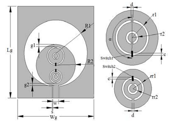
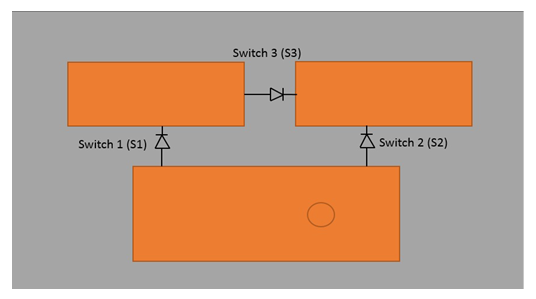
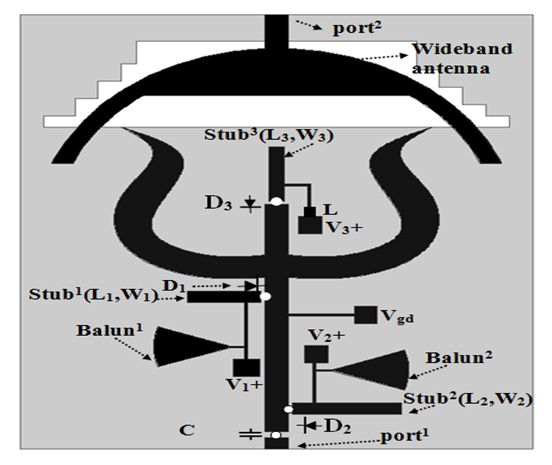
Antenna for cognitive radio application should be able to sense a wide range of frequencies and also should be able to reconfigure its frequency. Commonly used electronic switches for developing frequency-reconfiguration or impedance matching in antennas for wireless applications are, FETS, RF MEMS, VARACTOR Diodes, PIN Diodes and photoconductive switches. Another way of achieving antenna reconfiguration is by using mechanical means. This employs the use of actuators and motors to move a specific part of the antenna resulting in changes in the electrical properties of the antenna by altering its radiating edges, hence reconfiguration of the antenna parameter.
In [9], a single UWB antenna capable of frequency reconfiguration by the use of GaAs FET switches and stubs as shown in fig. 1 below was designed for cognitive radio application. The switches were used to connect and disconnect four stubs of different lengths to the main feed line of a circular disc monopole antenna with a partial ground. When all the switches are OFF, the antenna behaves like a UWB antenna, scanning the entire spectrum for holes. Combination of any of the switches in an ON and OFF position reconfigures the antenna frequency for narrow band communication over the channel with 20% increase in the overall gain. This antenna was able to reconfigure to four different frequency bands of: 2.1–2.6 GHz; 3.6–4.6 GHz and a dual band of: 2.8–3.4 GHz and 4.9–5.8 GHz.
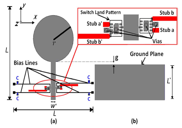
Figure 1. Configuration of the proposed Reconfigurable UWB antenna, (a) Top view (b) Bottom view [9]
The simulated radiation pattern shows that the H-plane pattern is omnidirectional while the E- plane pattern take is a doughnut shape and becomes directional at higher frequencies. Peak gain for the four reconfigurable bands is between 2.2 and 4.5 dBi, and the efficiency is greater 70%. The return loss is less than -10dB in the operating band.
In [10], a varactor diode was used to reconfigure slot antenna which is embedded in an elliptical disc monopole antenna. As shown in fig.2 below, the disc monopole acts as the UWB resonator for spectrum sensing covering between 3GHz – 11GHz and the narrow band slot antenna which was embedded at the center of the disc monopole is used for communication over the white space. By tuning the varactor placed across the slot the operating frequency changes between 5-6GHz. an offset feed technique was also used to the input impedance.
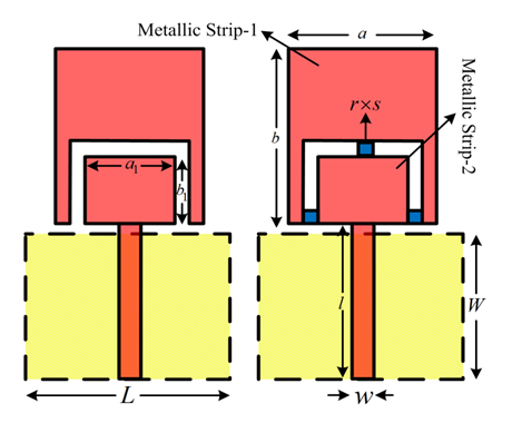
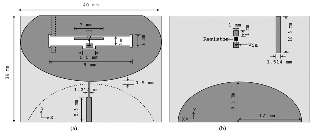
Figure 2. Configuration of the proposed UWB/Reconfigurable narrowband antenna, (a) Top view (b) Bottom view [10]
The radiation pattern changes to omnidirectional at higher frequencies while the peak gains for the reconfigurable frequencies of 5GHz, 5.5GHz and 6GHz are less than 2dB. Although the radiation efficiency is greater than 80% in the operating band. In this type of arrangement, there is an effect of mutual coupling between the two antennas which will degrade the radiation characteristic of the antenna.
In [11] UWB reconfigurable antenna was achieved with the use of a stepped slot antenna and PIN Diode switches. Additional slots created along the feed lines were shorted with the PIN diodes to make them frequency reconfigurable. Sensing of the UWB spectrum is archived through the stepped slots that resonate at three different frequencies and covers the UWB spectrum, while communication is achieved though different switching positions and combinations of five PIN diodes. The antenna has four switchable states: 2.810.7 GHz in UWB mode and 3.24.5, 4.37.8, and 7.911.2 GHz in communicating mode, covering the entire UWB spectrum. This makes it suitable for cognitive radio application.
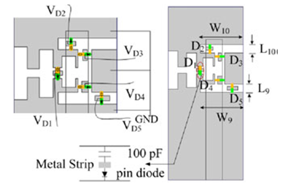
Figure 3. Proposed reconfigurable slot antenna with diode connections [11]
This slot antenna shown in fig 3 above, has wide bandwidth, omnidirectional radiation pattern, nearly constant gain throughout the UWB spectrum with more than 80% efficiency and a compact size. In [12], a dual port antenna comprising of a CPW fed NB slot antenna integrated into the tampered slot space of another uni- planar UWB slot antenna configuration was reported. The UWB slot antenna was able to cover between 2.6GHz – 11GHz, while the Narrow band slot antenna operates between 4.6GHz - 6.2GHz. It has 2:1 VSWR in both the UWB and the Narrow band region with good gain and directional radiation pattern though with a larger size. The antenna also has good isolation between ports.
Reported in [13], is an UWB rectangular DRA integrated with a NB DRA. The UWB and NB antenna has 2:1 VSWR bandwidth from 2.4 to 12 GHz and 2.3 to 4.5 GHz, respectively. The radiation pattern in the H- plane is symmetrical but not as such in the E-plane due to the presence of short circuited strip. The antenna has a stable gain around 5dBi with radiation efficiency greater than 80%. The issue of mutual coupling is worth mentioning here, though two symmetrical short-circuited strips were used to provide good isolation between the antenna ports. In [14], a more complex antenna design was reported. As shown in fig 4, the structure consists of a UWB antenna made up of an egg shaped monopole antenna and a narrow band communicating antenna made up of five different patches all on the same substrate. The UWB antenna is capable of sensing between 2.1 GHz to 10.6 GHz. reconfiguration is made possible by physical rotation of the five different patches through the use of a stepping motor mounted at the back of the antenna and controlled by an electronic circuitry. Rotation of difference patches produces different frequency at each time of rotation since the patches are designed at different center frequencies.
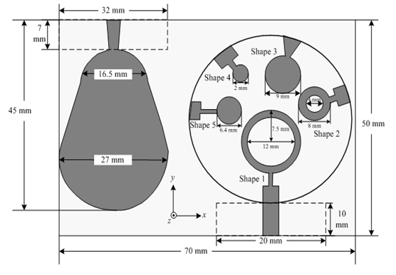
Figure 4. Antenna Structure [14]
The UWB antenna return loss shows that it can cover between 1.7GHz to 10.6GHz, which is the full FCC range. The radiation pattern for the five reconfigurable states is omnidirectional with peak antenna gain for the five patches between 8dB and 12dB. The size and the complex circuitry involve in this design seemed to be an issue.
Reported in [15] is an UWB antenna capable of reconfiguring up to four frequencies within the band 2.62-11GHz, by the use of two optically controlled microwave switches. These switches were connected to two narrow band complimentary split ring resonator (CSRR) etched on the radiating part of the UWB antenna. The upper CSRR on the patch produces switchable WiMax-band notch, and the lower one produces switchable WLAN-band notch. The arrangement is as shown in Fig. 5 below.
Figure 5. Reconfigurable UWB antenna using OCMS [15]
By controlling the two Optically Controlled Microwave Switches (OCMS) embedded in the narrow-band CSRRs, the antenna was able to achieve four reconfigurable band-notched states: a full FCC-allowed band, a WiMax-notched band, a WLAN-notched band, and a WiMax-WLAN-notched band. The antenna has a 2:1 VSWR in the UWB and The NB range with almost flat gain within the operating spectrum and a reduced gain at notched frequencies.
Some of the advantages of this designed antenna is that it requires about 100 mW optical powers to drive each OCMS, free DC-bias, perfect isolation of the controlled microwave signals from the controlling signals and fast switch action.
In [16] an UWB antenna was designed using two rectangular metallic strips separated from each other by etching some portion from the middle of the radiator. Three ideal switches were placed between the two metal strips to achieve re-configurability as shown in fig. 6 below.
Figure 6. Reconfigurable UWB monopole antenna [16]
This antenna is capable of operating in two frequency bands within the UWB. When the three switches are ON, it operates between 3-5GHz and when the three switches are OFF, it operates between 6-9GHz. this antenna produces nearly omnidirectional pattern at both the upper and the lower part of the UWB spectrum, but not throughout the spectrum.
Also reported in [17] is a monopole UWB antenna shown in fig 7 below with controllable notch for WLAN band that has two compact split ring resonators, SRR on both sides of the feed-line to create notch at 4.9 to 5.9 GHz. The two SRRs are reconfigured using two switches placed along the strip of the resonators. Activation and deactivation of the switches produces activation and deactivation of band notches.
Figure 7. Monopole UWB antenna with two SRRs near the feed line [17]
This antenna is proposed for microwave imaging and radar applications. In [18], a reconfigurable UWB antenna was designed using one main rectangular patch antenna, two parasitic rectangular elements and three ideal switches as shown in fig 8 below.
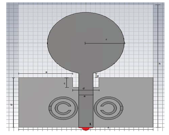
Figure 8. Schematic diagram of the proposed reconfigurable UWB patch antenna [18]
This arrangement is capable of producing coverage of 4GHz to 9GHz. depending on the arrangement of the switches; that is whether in ON or OFF position. Re-configurability is made possible by the three switches which are used to connect and disconnect the three patches.
Reported in [19] is a design of two UWB antennas of the same radiating element but different ground plane and number of slots. Slots were made both on the radiating patch and on the ground plane. Reconfigurability is provided by using PIN diodes within the slots. Both designs are capable of covering the entire UWB frequency range but the design with more slots and PIN diodes is able to achieve more frequency agility.
In [20], a hybrid antenna made up of a semicircular arc with staircase shape slotted ground with an excitation port 2 for wideband spectrum sensing and a simple stub-loaded antenna with another excitation port 1 for frequency agility on the same substrate was reported. When port 2 is excited, the antenna covers a wide spectrum of 1GHz to 12GHz, but when port 1 is excited, the antenna is capable of operating at four different frequencies; 2.1GHz, 2.96GHz, 3.5GHz and 5GHz. PIN diodes are used to electrically connect and disconnect the stubs to and from the microstrip feed line therefore making the antenna tunable as shown in Fig. 9 below.
Figure 9. Hybrid antenna layout [20]
This antenna has nearly a circular radiation pattern in the E- plane and an omnidirectional pattern in the H-plane. In all the operating frequencies, the VSWR is less than 2 and a return loss of better than -20dB.
Also reported in [21] is an antenna structure consisting of two semicircular patches fed by a microstrip feed line. The antenna is capable of wide spectrum sensing covering the range of 3GHz - 10GHz. with the incorporation of a DMS band pass T slot filter in the feed line. Integration of PIN diodes with this antenna makes is also capable of operating at six different narrowband frequencies between 5GHz to 10 GHz depending on position and combinations of the switches. The antenna has a reflection coefficient of below -10dB, an omni-directional radiation pattern which is almost constant in all cases and radiation efficiency better than 70%. In [22] reconfigurable filtennas were designed for both the inter-weave and the underlay cognitive radio system. A filtenna is an integration of either a band-pass or a band reject filter into an antenna structure. In the report a band-pass filter was integrated with a wide band antenna for interleave cognitive radio operation and a band-reject filter was also integrated with a UWB antenna for the underlay cognitive radio system. The band-pass filter which was integrated within the feed line of the antenna was designed using a stripline made of three subsections separated by two small gaps which allow the filter to have the band-pass behavior. A T-shaped slot was etched in the middle subsection, which made the band- pass filter frequency agile with the incorporation of PIN diodes. This arrangement forms the communicating antenna. The radiating patch of the sensing antenna consists of two identical half elliptically shaped conducting patches with partial ground. This antenna can cover between 3GHz and 6GHz. the combination of the band-pass filter and the sensing antenna forms what is called the filtenna. A pair of this antenna was designed on the same substrate with four excitation ports for MIMO operation i.e. two ports for the sensing antenna and two ports for the communicating antenna to minimize fading.
In any case dual-port antennas enable simultaneous sensing and communicating over the channel, but are restricted due to their relatively large size, coupling between the two ports and degraded radiation patterns. These limitations are solved by the use of single-port antennas, which are best suitable for channels that are not changing very fast, thus making sensing and communication sequentially possible [23].
For the underlay, a single wide band filtenna was designed, with a band reject filter integrated within the feed line of a wide band antenna having a u slot in both the ground plane and the feed line. This antenna is able to cover the UWB spectrum between 3GHz -10GHz and also provide band-reject at the lower frequency of (3.6 GHz) due to the u slot in the feed line while the one in the ground plane is responsible for the upper band-reject at (5.5 GHz). In [24], two patches, one rectangular and the other inverted U were nestled. PIN diodes were integrated in the U shaped slot between the two patches. Inset feed is used to ensure proper impedance matching of the antenna. By changing the states of the PIN diodes, the antenna can be switched to 1.87GHz, 3.55GHz, 3.67GHz and 5.6 GHz frequencies, making able to reconfigure for frequency bands of WIFI, GPS and WIMAX. Radiation pattern of this antenna remains constant and the return loss is less than -10dB.
Apart from the electrical and mechanical means of controlling frequency reconfiguration, change in material properties is also another technique that is getting the attention researchers. Though noteworthy are some of its limitations like slow tuning speed, high voltage requirements and small reconfiguration capabilities [25]. In [26] a dual band (UWB/NB) reconfigurable antenna was designed using a coplanar waveguide (CPW) fed circular monopole with PIN diodes and a moveable superstrate loaded with three pairs split ring resonator (SRRs) in its feed area. The superstrate position is mechanically controlled using a servo motor programmed by the Arduino Uno microcontroller. Switching between notched UWB and NB operation is provided by ON/OFF position of the two switches in the feed line while frequency reconfigurabilty is obtained through the movement of the moveable superstrate which has the SRRs printed on. This movement ensures that different SRR pair aligns with the slot in the feed section at a time resulting in three different frequency notched UWB responses at 6.5, 8.34, and 9.55 GHz. when the switches are ON and there is proper alignment of the SRR pair with the slot line, the antenna translates to a NB with responses at 6.57, 8.34, and 9.58 GHz.

4. Conclusions

Cognitive radio is a future technology for effective and spectrum efficient wireless communication which requires a good antenna in its front end. Some of the recent techniques employed in the design of antennas suitable for cognitive radio have been highlighted. Comparatively, most of the designs highlighted in this letter have omnidirectional radiation pattern which is good for cognitive radio system and indoor applications, 2:1 VSWR and efficiency greater than 70%. In some of the designs, size or complexity of the antenna will be an issue for portable wireless devices, while in some mutual coupling between UWB and NB antenna and interference from electronics switches biasing line which can affect the radiation characteristics of the antenna will be an issue. Therefore in choosing the best technique to use, attention must be given to factors like: the compactness, isolation of mutual coupling between ports, isolation of biasing line interference, radiation characteristics, frequency re-configurability and band notching to prevent interference from existing primary users.

References

[1]  F. Ghanem, M.H. Rijal, and P.S. Hall, On Antennas for Cognitive Radios, IEEE, -1- 4244-6051, 2011.
[2]  Lalj, H., Griguer, H. and Drissi, M. Design of Reconfigurable Band Notches Antenna for Cognitive Radio Applications. Wireless Engineering and Technology, 5, 99-105, July 2014.
[3]  Kumar, Nishant, P. Ananda Raju, and Santanu Kumar Behera, Frequency reconfigurable microstrip antenna for cognitive radio, applications, In Communications and Signal Processing (ICCSP), 2015 International Conference on, pp. 0370-0373. IEEE, 2015.
[4]  Y. Tawk, J. Costantine, and C. G. Christodoulou, Cognitive-Radio and Antenna Functionalities: A Tutorial, IEEE Antennas and Propagation Magazine, Vol. 56, No. 1, February 2014.
[5]  Mustafa S. Bakr, Ahmad Bader Alothman Alterkawi, Fabrizio Gentili, and Wolfgang B¨osch, Reconfigurable –Ultra –Wide –Band Antenna: Cognitive Radio, IEEE MTT-S International Microwave Workshop Series on Advanced Materials and Processes (IMWS-AMP 2017), 20-22 September 2017, Pavia, Italy.
[6]  Lise Safatly, Mario Bkassiny, Mohammed Al-Husseini, and Ali El-Hajj, Cognitive Radio Transceivers: RF, Spectrum Sensing, and Learning Algorithms Review, International Journal of Antennas and Propagation, Volume 2014, Article ID 548473, pages 1-22, 2014.
[7]  Tejbir Singh, Kuwar Arif Ali, Heena Chaudhary, D. R. Phalswal, Vishant Gahlaut and Pawan kumar singh, Design and Analysis of Reconfigurable Microstrip Antenna for Cognitive Radio Applications, Wireless Pers Commun Vol 98, 2163–2185, 2018.
[8]  Manikya Krishna Chaitanya Durbhakula, Venkata Koteswara Rao Nalam, Wide Band Patch Antenna Structures for Cognitive Radio Applications, 2017 IEEE 7th International Advance Computing Conference, (IACC), Hyderabad, 2017, PP. 434-439.
[9]  Tamer Aboufoul, Akram Alomainy, Clive Parini, Reconfiguring UWB Monopole Antenna for Cognitive Radio Applications Using GaAs FET Switches, IEEE Antenna and Wireless Propagation Letters., Vol. 11, 2012.
[10]  Elham Erfani, Javad Nourinia, Changiz Ghobadi, Mahmoud Nirro-Jazi, Tayeb A and Denidni, Design and implementation of an integrated UWB/Reconfigurable-Slot antenna for Cognitive Radio Applications, IEEE Antenna and Wireless Propagation Letters., Vol. 11, 2012, 77.
[11]  Gunjan Srivastava, Akhilesh Mohan, Ajay Chakrabarty, Compact Reconfigurable UWB Slot Antenna for Cognitive Radio Applications, IEEE Antenna and Wireless Propagation Letters., Vol. 16, 2017.
[12]  Gijo Augustin, Tayeb. A. Denidni, An integrated Ultra Wideband/Narrow Band Antenna in Uniplanar Configuration for Cognitive Radio System, IEEE Transactions on Antennas and Propagation, Vol. 60, No. 11, Nov. 2012.
[13]  Yongfeng Wang, Naizhi Wang, Tayeb A. Denidni, Qingsheng Zeng and Gao Wei, Integrated Ultrawideband/ Narrowband Rectangular Dielectric Resonator Antenna for Cognitive Radio, IEEE Antenna and Wireless Propagation Letters., Vol. 13, 2014.
[14]  Tummas, P. Krachodnok, R. Wongsan, A frequency reconfigurable Antenna design for UWB applications, 2014 11th international conference on Electrical Engineering/ Electronics, Computer, Telecommunications and information Technology(ECTI-CON), Nakhon Ratchasima, 2014, pp. 1-4.
[15]  Deshuang Zhao, Litao Lan, Yifei Han, Feng Liang, Qiaoli Zhang, and Bing-Zhong Wang, Optically Controlled Reconfigurable Band-Notched UWB Antenna for Cognitive Radio Applications, IEEE Photonics Technology Letters, Vol. 26, No. 21, November 1, 2014.
[16]  R. Khan et al., Reconfigurable UWB monopole antenna For Cognitive Radio Applications, 2016 International Conference on Computing, Electronics and Electrical Engineering (ICE Cube), Quetta, 2016, pp.59-62.
[17]  Anuja V. Golliwar, Milind S. Narlawar, YCCE, Nagpur, Multiple Controllable Band Notch Antenna for UWB Cognitive Radio Application, 3rd International Conference on Signal Processing and Integrated Networks (SPIN), 2016.
[18]  Mustafa S. Bakr, Ahmad Bader Alothman Alterkawi, Fabrizio Gentili and Wolfgang Bosch, Reconfigurable Ultra-Wide-Band Patch Antenna: Cognitive Radio, IEEE MTT-S International Microwave Workshop Series on Advanced Materials and Processes (IMWS-AMP 2017), 20-22 September 2017, Pavia, Italy.
[19]  G. A. Devi, J. Aarthi, P. Bhargav, R. Pandeeswari, M. A. Reddy and R. S. Daniel, "UWB frequency reconfigurable patch antenna for cognitive radio applications," 2017 IEEE International Conference on Antenna Innovations & Modern Technologies for Ground, Aircraft and Satellite Applications (iAIM), Bangalore, 2017, pp. 1-4.
[20]  Sonia Sharma, Chandra C. Tripathi, A Wide Spectrum Sensing and Frequency Reconfigurable Antenna for Cognitive Radio, Progress In Electromagnetics Research C, Vol. 67, 11–20, 2016.
[21]  N. Kumar, P. A. Raju, S. K. Behera, Frequency reconfigurable microstrip antenna for cognitive radio applications, 2015 International Conference on Communications and Signal Processing (ICCSP), Melmaruvathur, 2015, pp. 0370-0373.
[22]  Youssef Tawk, Joseph Costantine, Christos G. Christodoulou, Reconfigurable Filtennas and MIMO in Cognitive Radio Applications, IEEE Transactions on Atennas and Propagation, Vol. 62, No. 3, March 2014.
[23]  Lise Safatly, Mario Bkassiny, Mohammed Al-Husseini, and Ali El-Hajj, Cognitive Radio Transceivers: RF, Spectrum Sensing, and Learning Algorithms Review, International Journal of Antennas and Propagation, Volume 2014, Article ID 548473, pages 1-22, 2014.
[24]  Isra Nazir, Inam Elahi Rana, Noor ul Ain Mir, and Kanwal Afreen, Design and Analysis of a Frequency Reconfigurable Microstrip Patch Antenna switching between Four Frequency Bands, Progress In Electromagnetics Research C, Vol. 68, 179–191, 2016.
[25]  Joseph Costantine, Youssef Tawk, Silvio E. Barbin, and Christos G. Christodoulou, Reconfigurable Antennas: Design and Applications, Proceedings of the IEEE | Vol. 103, No. 3, March 2015.
[26]  Chinmoy Saha, Latheef A. Shaik, Rajesh Muntha, Yahia M.M. Antar, and Jawad Y. Siddiqui, A Dual Reconfigurable Printed antenna, IEEE Antennas & Propa gation, 18, 1045-9243, 2 0 1 8.