Dhirgham K. Naji
Department of Electronic and Communications Engineering, College of Engineering, Al-Nahrain University, Baghdad, Iraq
Correspondence to: Dhirgham K. Naji, Department of Electronic and Communications Engineering, College of Engineering, Al-Nahrain University, Baghdad, Iraq.
| Email: |  |
Copyright © 2018 The Author(s). Published by Scientific & Academic Publishing.
This work is licensed under the Creative Commons Attribution International License (CC BY).
http://creativecommons.org/licenses/by/4.0/

Abstract
Three multiband microstrip patch antennas (MPAs) to operate at (3.5/5.5 GHz) WiMAX, upper (5.2/5.8 GHz) WLAN and C frequency bands are presented in this paper. The proposed antenna structures are mainly constructed from the fork-shaped monopole antenna. These three antennas (Ant.1-3) are namely mender fork-shaped antenna (MFA), spiral fork-shaped antenna (SFA) and double SFA (DSFA). All antennas are fed by coplanar waveguide (CPW) structure and printed on the front side of FR substrate with surface area of 21×21 mm2. A new approach is presented for designing the proposed antennas to resonate at the specified operating frequency bands. Initially, a conventional MPA fed by microstrip-line is designed to operate at 5.8-GHz WLAN band. Then, intermediate antenna prototype structures are obtained during the design process until achieving the desired antennas. The Ant.1 and Ant.3 gives dual-band characteristic covering 5.2/5.8 GHz-WLAN band including 5.150–5.875 GHz and 3.5/5.5 GHz-WiMAX including 3.4–3.7 GHz and 5.25–5.85 GHz, respectively. The Ant.2 gives tri-band covering the aforementioned dual-band besides to C-band 7.25 GHz (6.84 – 7.50 GHz). An electromagnetic simulator CST MWS ver. 2018 was used to analyze the designed antennas. The simulated results demonstrate that a dual- and tri-band operation can be easily provided by these antennas as well they have good dipole-like and omnidirectional radiation characteristics, stable gain and high-radiation efficiency indicating that the proposed antennas are candidate for WLAN/WiMAX applications.
Keywords:
Fork-shaped antenna (FA), Microstrip patch antenna (MPA), Multiband antenna
Cite this paper: Dhirgham K. Naji, Design of Compact Dual-band and Tri-band Microstrip Patch Antennas, International Journal of Electromagnetics and Applications, Vol. 8 No. 1, 2018, pp. 26-34. doi: 10.5923/j.ijea.20180801.02.
1. Introduction
In recent years, wireless communication systems such as Worldwide Interoperability for Microwave Access (WiMAX), wireless local area network (WLAN) and C-Band have highly attractive and been widely used. Therefore, the demand for low-profile antennas with compact size, and multiband operation covering the bands of these applications, as well as omnidirectional coverage and simple planar structures is in urgent need [1]. The standard operational frequency bands of WLAN and WiMAX technologies that need to be covered by the antenna are: 2.4/5.2/5.8-GHz WLAN band (2.4–2.484 GHz, 5.15–5.35 GHz and 5.725-5.875 GHz) and 2.5/3.5/5.5-GHz WiMAX (2.5–2.69 GHz, 3.4–3.7 GHz and 5.25–5.85 GHz) [2]. It is well-known that the antenna that meet these requirements is the microstrip patch antenna (MPA). However, conventional MPA with regular patch shape, rectangular and circular, have large physical size, narrow bandwidth and poor radiation efficiency that made it unable to satisfy the main requirements of modern communication systems, compactness and multiband characteristic [3]. To overcome these drawbacks of conventional MPAs, lots of techniques have been carried out by the researchers’ works for designing compact and multi-band MPAs [4]. In the available literature, several techniques have been reported for designing compact multiband printed antennas. Techniques based on metamaterial aids in creation multiband operation and antenna miniaturization [5]. Moreover, rectangular MPA loaded with mender lines and using spiral strips can lead to antenna having multiband operation with more size reduction [6]. In addition, defected ground structure with U- and L-strips can contribute to miniaturized multiband antenna design due to their ability for impedance matching enhancement and improvement in antenna radiation’s capacity [7]. Multiband operation and antenna size miniaturization could be achieved by utilizing the well-known features, self-similarity and space filling, of fractal geometry [8, 9]. Recently, the coplanar waveguide (CPW) feeding techniques have been attractive by researchers aiming of improving antenna performance and attain the multiband characteristics. In literature, antennas fed by CPW structure provide many advantages over other feeding, e.g., microstrip- and coaxial probe-fed, include: low cost, less dispersion, good omnidirectional pattern, minimum surface wave and having single-metallic layer made it easily integrated with passive and active elements [10-13]. Because of these interesting features, the CPW is preferred to be used here for designing the proposed antennas. There are many CPW-fed MPAs introduced in recent literatures for WLAN/WiMAX applications such as [14-18]. For instance, a CPW-fed antenna [14] consists of an asymmetric ring, an inverted L-strip, and a straight strip to obtain tri-band covers the WLAN (2.4/5.2/5.8 GHz) and WiMAX (3.5/5.5 GHz) bands. In [15] a planar monopole antenna fed by CPW with stop band characteristic was proposed by adding at the edge of ground one pair of open-circuited stubs. The antenna has compact size of 3045 mm2 with notch band of 1.4 GHz (3.84-5.25 GHz), covering the entire WiMAX (3.05-3.84 GHz) and WLAN (5.24-7.54 GHz). Tri-band metamaterial inspired open split ring resonator antenna, covering 2.4/5.2/5.8 GHz (Wireless LAN), 5.5 GHz (WiMAX) and 7.4 GHz (C-band) applications was presented in [16]. In [17], a new approach for designing miniaturized multiband patch antennas was introduced. Antenna miniaturization is achieved by shorting one edge of the patch whereas multiband operation is obtained by insertion inverted multiple U-shapes. Another technique for antenna miniaturization with independently controllable frequency bands is based on loading an antenna with three uncoupled resonators [18]. The designed antenna can operate at 2.6, 3.35, 5.15, and 6.1 GHz. Although, the aforementioned design techniques have successively attained antennas with compact size and multiband operation but most of these designed antennas having additional structure or being complex to be fabricated. In this work a new design approach is introduced for achieving dual- and tri-band MPAs suitable for WiMAX/WLAN and C-band applications. Three compact MPAs have been successively designed to cover the frequency bands of these applications. The design of these antennas are mainly based on the fork-shaped monopole antenna and are namely mender fork-shaped antenna (MFA), spiral fork-shaped antenna (SFA) and double SFA (DSFA). All antennas are printed on FR4 substrate and they are modeled and analyzed by using CST MWS simulator tool. The CST simulated result reveals that the proposed designed antennas promise good performance results in terms of operating frequency bands and omnidirectional patterns as well as stable gains and radiations efficiencies.The remaining of this paper is organized as follows. In Section 2, the proposed antenna configurations and the design approach for designing these antennas is presented and discussed in details. Section 3 reviews the performance and discussion of the simulated results along with the features of the designed antennas, with conclusions is drawn in Section 4.
2. Antenna Design and Configuration
This section describes and investigates in detail the geometrical configuration and a procedure for designing three compact dual- and tri-band antennas for WiMAX/WLAN and C-band applications. The concept of designing these three antennas are based on the fork-shaped monopole antenna structure. An intermediate design steps were conducted until achieving the final proposed antennas.
2.1. Antenna Configuration
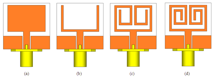
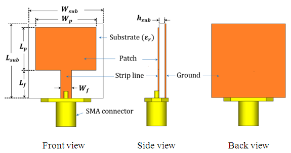
The 3D simulation models of the final proposed designed antenna structures are shown in figure 1. These antennas are called, meandered fork-shaped antenna (MFA), spiral fork-shaped antenna (SFA), and double spiral fork-shaped antenna (DSFA), figure 1(a-c), respectively. All antennas are printed on the front side of FR4 substrate with thickness  of 1.6 mm and relative permittivity
  The total substrate footprint
 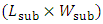 of all antennas is (21mm × 21mm). Each patch structure of these antennas are constructed as a radiating strips of width
  which are placed within an occupied dimension, patch length
  patch width
  of (12mm × 17mm). The coplanar waveguide (CPW) structure, characterized by ground length
  and gap distance
  between feeding strip length and width
  and
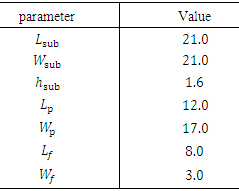
and  , respectively, was used for feeding these antennas through sub-miniature-A (SMA) connector. The optimized values of antenna parameters are listed in Table 1.
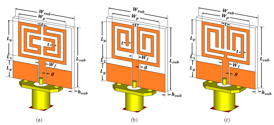 | Figure 1. Configuration of the proposed antenna structures. (a) Meandered fork-shaped antenna (MFA). (b) Spiral fork-shaped antenna (SFA), and (c) Double spiral fork-shaped antenna (DSFA) |
Table 1. Antenna design parameters for the proposed antennas
 |
| |
|
2.2. Design Procedure
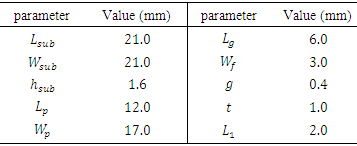
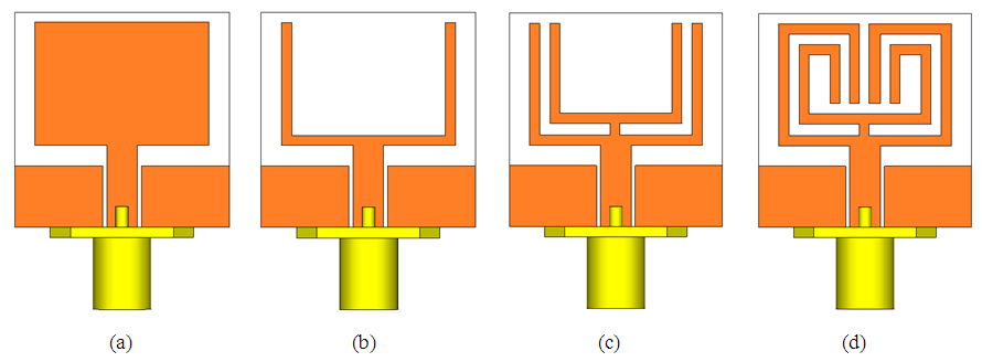
Figures 2-4 display the design evolution process for each one of the three designed antenna, MFA, SFA, and DSFA, respectively. Initially, the design procedure begins by using the standard equations of transmission line model as a guideline for designing a conventional microstrip patch antenna (MPA) fed by microstrip line from which its counterpart MPA fed by CPW feeing structure is obtained. Thus, this represent the first step in the procedure for designing the proposed antennas and as a result, a reference antenna (RA) is obtained and this is shown in figures 2(a), 3(a) and 4(a). In the next section, a design of strip-fed MPA and RA and their performance results are discussed in details. | Figure 2. Investigated design evolution process of meandered fork-shaped antenna (MFA). (a) Reference antenna, RA. (b) Fork-shaped antenna, FA. (c) MFA1, 1-turn. (c) MFA2, 2-turn (the proposed Ant.1) |
 | Figure 3. Investigated design evolution process of spiral fork-shaped antenna (SFA). (a) RA. (b) FA. (c) SFA1, 1-turn. (c) SFA2, 2-turn. (the proposed Ant.2) |
 | Figure 4. Investigated design evolution process of double spiral fork-shaped antenna (DSFA). (a) RA. (b) FA. (c) DFA. (c) DSFA1. (the proposed Ant.3) |
The second design step is to form MPA that based on fork-shaped radiating patch that evolved from RA. This designed antenna, as figure 2(b), 3(b) and 4(b) show, is namely fork-shaped antenna (FA). The first and second design steps are common to be performed for designing the three proposed antennas. An additional two design steps were added in the design evolution process for each one of the three types of antenna, MFA, SFA, and DSFA. As shown in figure 2(c) and (d), we have obtained a simple antenna structure, MFA, after generation 1-turn (MFA1) and 2-turn (MFA2), respectively. In the same manner, SFA has achieved when performing 1-turn (SFA1) and 2-turn (SFA2) as depicted respectively in figure 3(c) and (d). Finally, DSFA is designed after 1-turn of iteration is applied to double FA and as a result we have obtained a third type of the proposed antenna (DSFA1), see figure 4(c) and (d), respectively.
2.3. Design Guideline for Conventional MPA
According to the transmission line model, the following Eqns. (1)-(5), [19] can be used as a five guideline design equations for calculating the geometrical parameters, patch width  and patch length
  of the conventional MPA (as in figure 5) by assuming the resonant frequency
  the relative permittivity and the height of the substrate
  and
and  are given. In summary, the guidelines for designing the conventional MPA are outlined as follows:i) Firstly, for a good patch radiator,
  that leads to efficient radiation is determined using (1)
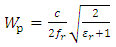 | (1) |
where  is the speed of light in free space.ii) Determine the substrate’s effective permittivity
  by applying (2)
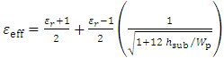 | (2) |
iii) Calculate the extension of the patch length  using (3).
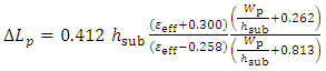 | (3) |
iv) Finally,  can be found after substituting (4), the effective patch length
  , in (5)
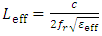 | (4) |
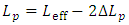 | (5) |
 | Figure 5. Conventional microstrip-fed MPA |
Now, we begin to design a conventional MPA which considered as the first step for designing the proposed antennas. Firstly, by substituting all specified parametric values, 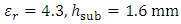 , and
, and  , the center frequency of 5.8-GHz WLAN band (5.725 – 5.875 GHz), in Eqns. (1)-(5), the patch antenna length and width are calculated to be
 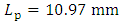 and
and 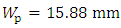 , respectively. Then, a full wave electromagnetic CST MWS simulator is used to analyze and simulate the designed antenna by fine-tuning the antennas’ geometrical parameters and the optimized values of these parameters are listed in Table 2. The obtained CST simulated return loss result for the designed antenna as figure 6 shows, an antenna is resonating at
  with -10dB S11 bandwidth of
  ranging from 5.7-5.9 GHz and the total radiation is in the front direction of antenna. This antenna having patch dimensions
  of (12 mm×17 mm) and the total substrate footprint dimension occupied by antenna
 is (21 mm×21 mm).
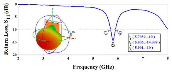 | Figure 6. S11 plot and radiation pattern for the conventional strip-fed MPA |
Table 2. Conventional microstrip-fed patch antenna design parameters [unit: mm]
 |
| |
|
2.4. Design of A Reference Antenna
Having successively conventional MPA was designed based on the design equations (1)-(5) for resonating at the desired resonance frequency,  . A reference antenna (RA) fed by CPW is required to be resonated at
  , the center frequency of 3.5 GHz-WiMAX band (3.40–3.70 GHz) and 5.80 GHz-WLAN band
  i.e.,
i.e., 
 To do that, initially, a previously MPA is redesigned with the same geometrical parameters except of using a partial ground of length
  at the back side of the substrate, see figure 7(a). Later on, a MPA with strip feed is replaced with a counterpart CPW feed to produce the desired reference antenna (RA) as shown in figure 7(b). Figure 8 shows the return loss S11 plot for applying both the microstrip feeding and CPW feed to the designed antennas. Table 3 summarizes the main performance parameters of these antennas, resonance frequency
  , lower and higher
  frequencies,
  and
and  , bandwidth
 , gain
  and radiation efficiency
  at
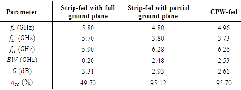
at  . It is demonstrated from observation figure 8 and Table 3 that RA with CPW feeding technique has wider impedance bandwidth of 2.53 GHz as well as microstrip-fed MPA with partial ground has
  while conventional MPA has a narrow BW of
  Furthermore, RA with CPW is more efficient in terms of radiation efficiency, greater than 97%, compared with the other two antennas. Figure 9 depicts the simulated far-field realized gain radiation pattern of the RA at both 3D and 2D
 plots at
  It is observed from this figure that the RA has an omnidirectional pattern suitable for wireless communication application compared with the conventional microstrip-fed MPA which has a boresight directional radiation pattern.
Table 3. Comparison of conventional MPAs performance parameters
 |
| |
|
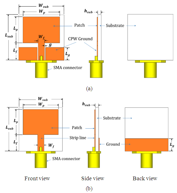 | Figure 7. (a) Microstrip-fed MPA with partial ground. (b) CPW-fed MPA, the reference antenna (RA) |
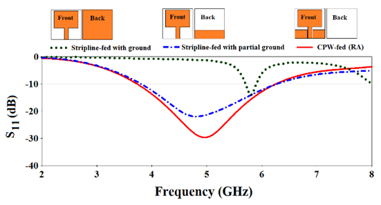 | Figure 8. CST simulated return loss curves of various antennas |
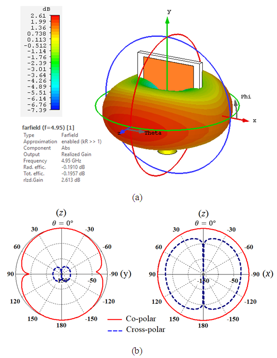 | Figure 9. Far-field realized gain radiation pattern of RA at 5.0 GHz. (a) 3D. (b) 2D in yz- and xz-plane |
3. Numerical Results and Discussion
After that the procedure for antenna structures in the previous section is suggested for the designed antennas for operating in the standard WiMAX (3.3 – 3.7 GHz), WLAN (5.15 – 5.875 GHz) and C-band frequency ranges. The return loss, surface current distribution as well as the radiation pattern, gain and efficiency are the main performance parameter results that will be deduced her to validate the design concept. All computational models of the proposed antenna structures are implemented in the electromagnetic software CST Microwave Studio ver. 2018 and its time-domain solver is used to obtain these results. To improve the accuracy of the numerical results, SMA connectors were incorporated in the implemented models.
3.1. Return Loss
In this subsection a return loss, S11 for the proposed antennas Ant. 1 (MFA), Ant. 2 (SFA) and Ant. 3 (DSFA) is discussed and investigated in details. Figure 10(a-c) shows the S11 plot for intermediate antennas that belong to each type of the three designed antennas, MFA, SFA and DSFA, respectively. The return loss and VSWR results of the finalized prototype antenna structures have been summarized in figure 11 and their quantitative analysis in terms of  and
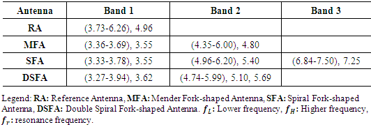
and  are listed in Table 4. It can be observed that the MFA and DSFA gives dual-band (Band 1 and 2) whereas SFA gives tri-band characteristic (Band 1 - 3). The frequency bands satisfied by the proposed antennas can be summarized as follows:
Table 4. Comparison of the proposed antenna -10 dB bandwidth,
 (in GHz) (in GHz)
 |
| |
|
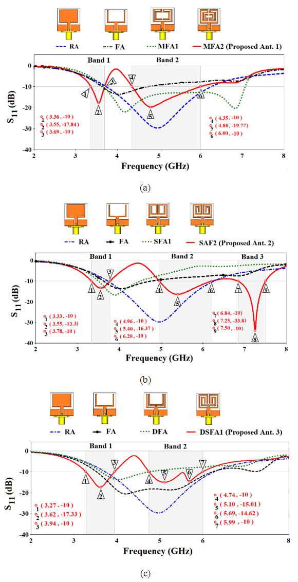 | Figure 10. Simulated return losses S11 curves for the various design evolution process for each one of the three proposed antennas. (a) MFA, mender fork-shaped antenna. (b) SFA, spiral fork-shaped antenna. (c) DSFA, double spiral fork-shaped antenna |
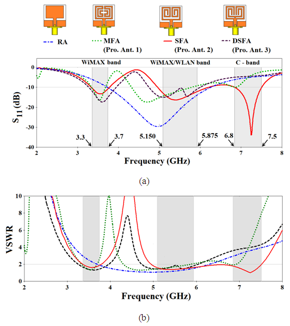 | Figure 11. Simulated S11 (a) and VSWR (b) for the proposed antennas |
Ÿ Ant. 1 or MFA: WiMAX band 3.55 GHz (3.36 – 3.69 GHz) and WLAN band 4.80 GHz (4.35 – 6.00 GHz).Ÿ Ant. 2 or SFA: WiMAX band 3.55 GHz (3.33 – 3.78 GHz), WLAN band 5.40 GHz (4.96 – 6.20 GHz) and C-band 7.25 GHz (6.84 – 7.50 GHz).Ÿ Ant. 3 or DSFA: WiMAX band 3.62 GHz (3.27 – 3.94 GHz) and WLAN band 5.10/ 5.69 GHz (4.74 – 5.99 GHz).Thus, these compact antenna structures cover the useful frequency bands that need for wireless communication systems such as 3.5-GHz WiMAX (3.3-3.7 GHz) band, WLAN (5.150 – 5.875) band and C band.
3.2. Surface Current Distribution
In order to clarify the return loss performance for the proposed antenna structures, figure 12(a-c) depicts the current distribution plots on the antenna surface (Ant. 1-3), respectively at the specified frequency in each band, 3.5 GHz (Band 1), 5.8 GHz (Band 2) and 7.25 GHz (Band 3). It is observed that the intensity of radiation current at 3.5 GHz, the left-hand side of figure 12(a-c), for each antenna is more concentrated in the inner strips, along the CPW feeding line and at edges of the ground plane than that in the outer strips. Similarly, at 5.8 GHz, the surface current is flowing at perimeter of the outer patch strips of antennas. This agrees well with the fundamental concept of antenna theory that the surface current at lower frequency (larger wavelength) is flowing in more paths than that at higher frequency (shorter wavelength). As a result, the antenna is more efficient in terms of radiation efficiency and gain at upper frequency band than that at lower frequency band and this will be proved in the next section. 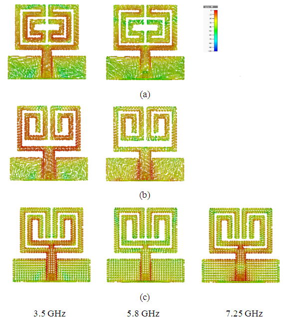 | Figure 12. Simulated results of the surface current distributions for the proposed antennas. (a) MFA. (b) SFA. (c) DSFA |
3.3. Realized Gain and Efficiency
The realized gain and efficiency against frequency for the proposed antennas at operating frequency bands are shown in figure 13(a) and (b), respectively. It is observed that the gain and efficiency of DSFA at lower frequency band is the lowest one whereas it is the highest one in the middle band compared with the other two antennas. On the other hand, the gain and efficiency of MFA and SFA are nearly coincide with each other for frequencies within lower and upper bands. As stated in the previous section, figure 13 demonstrate that more gain and efficacy can be obtained at higher frequency band than at lower frequency band and this is true for the antennas, MFA and SFA but in contrast, DSFA is more efficient in lower range of frequencies. Thus, at higher frequency band, the DSFA is less efficient for radiation in comparison with the other two antennas. | Figure 13. Simulated realized gain (a) and total efficiency (b) for the proposed antennas |
3.4. Radiation Pattern
Figures 14 (a) and (b) show the 2-D radiation pattern in terms of  and
and  at 3.5 GHz, 5.8 GHz and 7.25 GHz. It is clear from this figure that all antennas have nearly an omnidirectional radiation pattern in H-plane and approximately radiate in eight shapes (8) in E-plane at lower and middle frequency bands but somewhat distorted radiation at higher frequency band.
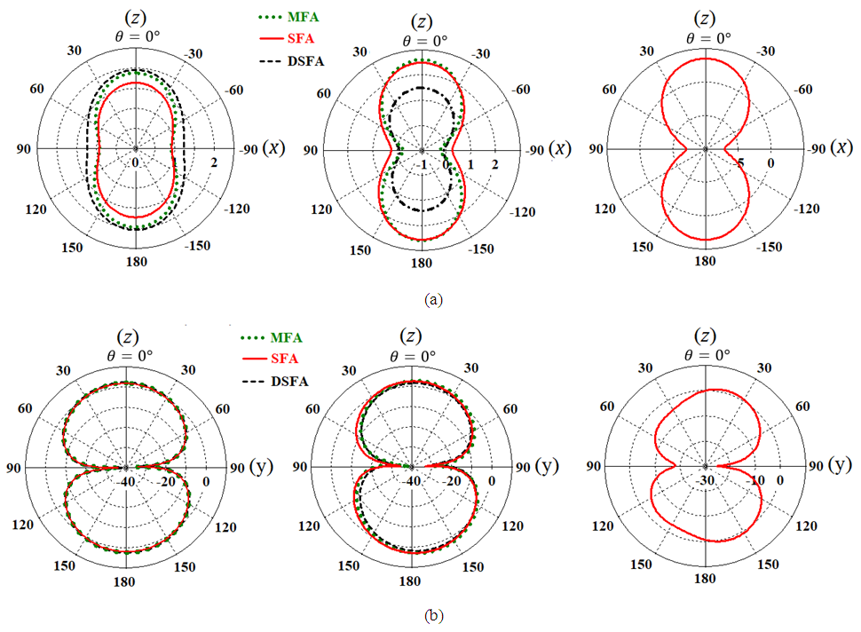 | Figure 14. H-plane pattern (a) and (b) E-plane pattern for the proposed antennas. From the left- to right-hand-side plots are for the frequencies of 3.5, 5.8 and 7.25 GHz, respectively |
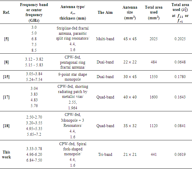
Table 5 depicts that the proposed antennas have advantages, more size reduction and simple antenna structures, over the previous reference designs, such as [5], [8], [15], [17, 18].Table 5. A comparison between recent reported multiband antennas and the proposed antenna
 |
| |
|
4. Conclusions
This paper presents the design of three compact multiband microstrip antennas, Ant.1, Ant.2 and Ant.3. The Ant.1 and Ant. 3 are useful for dual-band whereas Ant.2 is useful for using as tri-band antenna. These antennas cover the useful frequency band of modern communication systems such as (3.5/5.5) WiMAX (3.3 – 3.7 GHz / 5.25 – 5.85 GHz) bands, (5.2/5.8) WLAN (5.15 – 5.35 GHz / 5.725 – 5.875 GHz) bands and C-band. Ant. 1 covers the WiMAX band 3.55 GHz (3.36 – 3.69 GHz) and WLAN band 4.80 GHz (4.35 – 6.00 GHz). Ant. 2 covers the WiMAX band 3.55 GHz (3.33 – 3.78 GHz), WLAN band 5.40 GHz (4.96 – 6.20 GHz) and C-band 7.25 GHz (6.84 – 7.50 GHz). While, Ant. 3 covers the WiMAX band 3.62 GHz (3.27 – 3.94 GHz) and WLAN band 5.10/ 5.69 GHz (4.74 – 5.99 GHz). The designed antennas are characterized as simple structures to be manufactured and compact in size (21 × 21 × 1.6 mm3). Besides, simulated radiation pattern of these antennas exhibit that the designed antennas have omnidirectional radiation make them suitable for using in the portable wireless devices.
References
| [1] | Li W-W, Su J-S, Zhou J-H, Shi Z-Y.: ‘Compact wide triband multicavity-coupled slot antenna’. Microw Opt Technol Lett. 2017; 60:157–163. |
| [2] | Wong H, Luk K-M, Chan CH, Xue Q, So KK, Lai HW: ‘Small antennas in wireless communications’. Proc IEEE. 2012; 100(7): 2109–2121. |
| [3] | Mojtaba Fallahpour and Reza Zoughi: ‘Antenna Miniaturization Techniques’. IEEE Antennas & Propa gation Magazine, Feb. 2018. |
| [4] | Geetanjali1 and Rajesh Khanna: ‘A Review of Various Multi-Frequency Antenna Design Techniques’. Indian Journal of Science and Technology, vol. 10 (16), April 2017. |
| [5] | Ali T, Khaleeq MM, Pathan S, Biradar RC: ‘A multiband antenna loaded with metamaterial and slots for GPS/WLAN/WiMAX applications’. Microw Opt Technol Lett., 60: 79–85, 2017. |
| [6] | Kunal Srivastava, Ashwani Kumar and Binod K. Kanaujia: ‘Design of Compact Penta-Band and Hexa-Band Microstrip Antennas’. Frequenz 2016, |
| [7] | Yifan Mao, Songtao Guo, Menggang Chen: ‘Compact dual-band monopole antenna with defected ground plane for Internet of things’. IET Microw. Antennas Propag., vol. 12, Iss. 8, pp. 1332-1338, 2018. |
| [8] | Dhirgham K. Naji: ‘Compact Design of Dual-band Fractal Ring Antenna for WiMAX and WLAN Applications’. International Journal of Electromagnetics and Applications, 6(2): 42-50, 2016. |
| [9] | Vipul Sharma, Neeraj Lakwar, Nitin Kumar, Tanuj Garg: ‘Multiband low-cost fractal antenna based on parasitic split ring resonators’. IET Microw. Antennas Propag., vol. 12, Iss. 6, pp. 913-919, 2018. |
| [10] | Pandeeswari, R., Raghavan, S.: ‘A CPW-fed triple band OCSRR embedded monopole antenna with modified ground for WLAN and WIMAX applications’. Microw. Opt. Technol. Lett., 57, pp. 2413–2418, 2015. |
| [11] | Elavarasi, C., Shanmuganantham, T.: ‘Multiband SRR loaded Koch star fractal antenna’. Alexandria Eng. J., pp. 1–7, 2017. |
| [12] | M. S. Sedghi, M. N.-Moghadasi, and F. B. Zarrabi, “A dual band fractal slot antenna loaded with Jerusalem crosses for wireless and WiMAX Communications”, Progr. In Electromagn. Res. Lett., vol. 61, pp. 19–24, 2016. |
| [13] | Karimbu Vallappil A, Khawaja BA, Khan I, Mustaqim M.: ‘Dual-band Minkowski–Sierpinski fractal antenna for next generation satellite communications and wireless body area networks’. Microw Opt Technol Lett. 2017. |
| [14] | Shanshan Huang, Jun Li, and Jianzhong Zhao: ‘Miniaturized CPW-Fed Triband Antenna with Asymmetric Ring for WLAN/WiMAX Applications’. Hindawi Publishing Corporation Journal of Computer Networks and Communications, 2014. |
| [15] | Tapan Mandal, Santanu Das: ‘Coplanar waveguide fed 9-point star shape monopole antennas for worldwide interoperability for microwave access and wireless local area network applications’. J Eng, Iss. 4, pp. 155–160, 2014. |
| [16] | Rengasamy Rajkumar, Kommuri Usha Kiran1: ‘A Metamaterial Inspired Compact Open Split Ring Resonator Antenna for Multiband Operation’. Wireless Pers Communm, 2017. |
| [17] | Boukarkar, A.; Lin, X.Q., Jiang, Y.; Yu, Y.Q.: ‘Miniaturized single-feed multiband patch antennas’. IEEE Trans. Antennas Propag, 65 (2), 850–854, 2017. |
| [18] | Mahmoud a. abdalla1 and zhirun hu: ‘Design and analysis of a compact quad band loaded monopole antenna with independent resonators’. International Journal of Microwave and Wireless Technologies, 2018. |
| [19] | Constantine A. Balanis. “Antenna Theory Analysis and Design”. John Wiley & Sons, 4th edition, 2016. |

 Abstract
 Reference
 Full-Text PDF
 Full-text HTML