Khalil H. Sayidmarie, Abdul-Rahman Shakeeb
Department of Communication Engineering, College of Electronic Engineering, Ninevah University, Mosul, Iraq
Correspondence to: Khalil H. Sayidmarie, Department of Communication Engineering, College of Electronic Engineering, Ninevah University, Mosul, Iraq.
| Email: |  |
Copyright © 2017 Scientific & Academic Publishing. All Rights Reserved.
This work is licensed under the Creative Commons Attribution International License (CC BY).
http://creativecommons.org/licenses/by/4.0/

Abstract
The conventional beam scanning in phased arrays requires either frequency scanning or phase variation for the array elements, which raise complexity and cost. Another way is presented which is simplest and inexpensive by varying the amplitude excitation of the two tilted sides of the array. Thus there is neither a need for phase variation nor a frequency sweeping. Theoretical analysis and computer simulations are presented to investigate the performance of the proposed amplitude scanning technique. The results of using two half-wave dipole elements show that the mainbeam can be scanned across ±30° with less than 1.8dB variation in the magnitude of the mainbeam.
Keywords:
Switched beam antennas, Reconfigurable antennas, Amplitude-only scanning, Scanned arrays, Phased arrays
Cite this paper: Khalil H. Sayidmarie, Abdul-Rahman Shakeeb, Array Beam Scanning and Switching by Variation of Amplitude-Only Excitations, International Journal of Electromagnetics and Applications, Vol. 7 No. 2, 2017, pp. 25-30. doi: 10.5923/j.ijea.20170702.01.
1. Introduction
Beam-steering antennas are necessary solutions for a variety of applications such as search, tracking, traffic control and collision avoidance radars [1, 2]. The increasing pollution of the electromagnetic environment has promoted the study of beam scanning and nulling techniques [3]. In other applications, it is required to modify the radiation pattern so that better coverage or reception is achieved. This has promoted research into smart base station antennas for WLAN and cellular communication as well as reconfigurable antennas. Various concepts for achieving beam steering have been investigated such as phase-only scanning, frequency scanning and different configurations of beam forming networks. These methods are dependent on supplying linear phase across the array elements [1, 2]. The performance is influenced by the characteristics of the phase shifters which can be bulky, of limited sweep range and of performance that varies with the frequency of operation. The digital delay lines can offer better performance, however, they are fabricated to give few discrete phase values thus resulting in stepped scanning angles.The frequency scanning techniques require certain bandwidth which may not be available to the system due to the fast increase in the number of users and the scarcity of the frequency spectrum. To override the problems encountered in frequency and phase scanning systems, a beam steering technique that employs a variation of the amplitude excitations of few elements of the array was presented in [4, 5]. The technique does not require variable phase shifters, nor it needs frequency scanning. However, it requires variable power dividers to change excitations of some of the array elements, and a single fixed phase shifter. In [4] the idea of amplitude scanning technique was investigated using a 3-element array, while in [5] a developed version of the technique was investigated.In [6] the Bee Algorithm was utilized to find the element amplitudes of a linear antenna that are required to steer a single, multiple and broad-band nulls to reject the interference. A simple beam steering for a broadband microstrip antenna was presented in [7]. PIN diodes connecting stubs to a partial ground plane were utilized to achieve the beam steering. An Electronically Steerable Parasitic Array Radiator (ESPAR) that has the ability to steer the main beam along either H-plane or E-plane with low side-lobe level was presented in [8]. The beam steering was achieved by adjusting the reactive loads of the associated passive patch elements. A multifunctional reconfigurable antenna (MRA) operating in nine modes was presented in [9]. The antenna consists of an aperture coupled driven patch antenna with a parasitic layer of 3×3 electrically small square metallic patches fixed on the surface of the parasitic layer. PIN diode switches are used to configure the geometry of the parasitic surface. The antenna provided an average 6 dB (SNR) gain improvement compared to the conventional omni-directional antenna. However, the switching of the 12 PIN diodes needs a complex drive network. In a recent development of the reconfigurable antenna of [9], a broadband reconfigurable antenna that could steer the mainbeam in 3 different directions has been recently presented [10]. The antenna has 3×2 parasitic small patches placed above the driven patch. PIN diode switching is used to provide three beam-steering directions of the radiation pattern [10]. A similar idea of the switched parasitic patches was used in the design and fabrication of a 60 GHz antenna for WLAN applications [11].In this contribution, the same goal is approached in a different way where two similar element antennas are tilted by a certain angle from a common base-line and are fed through two lines. By controlling the excitations of the two side-antennas, the combined main beam can be steered from the normal to one antenna to that of the other antenna. This idea neither requires phase shifters nor frequency scanning. Moreover, it offers the flexibility to design the antenna to the required characteristics apart from the limitations of the scanning requirements, while the steering can hardly affect the performance of the antenna.
2. The Proposed Amplitude Scanning Technique
The geometry of the proposed antenna is shown in Fig. 1-a, where two identical element antennas are inclined by an angle ɸ with respect to the common baseline along the X-axis. The left and right elements are assumed to have broadside radiation patterns with peak radiation normal to each antenna (that is shifted by an angle ɸ to the right and left of the Y-axis respectively). When the two elements are fed by the same signal then, the combined radiation pattern will be along the Y-axis. Therefore, by a simple switching of the feeds of the two elements, the resulting pattern can be switched into three main directions as depicted in Fig. 1-b. The antenna arrangement can have three modes of radiation patterns. The first is along the Y-axis when both elements are fed by the same signal, while in the second mode the main beam is switched to the left of the Y-axis by an angle ϕ when the left element is switched off. Thirdly, the main beam can be switched to the right of the Y-axis when the right element is switched off. Scanning of the main beam between the second and third states can also be achieved if the signal supplied to one of the two elements is reduced gradually down to the switching off state as explained in the next section.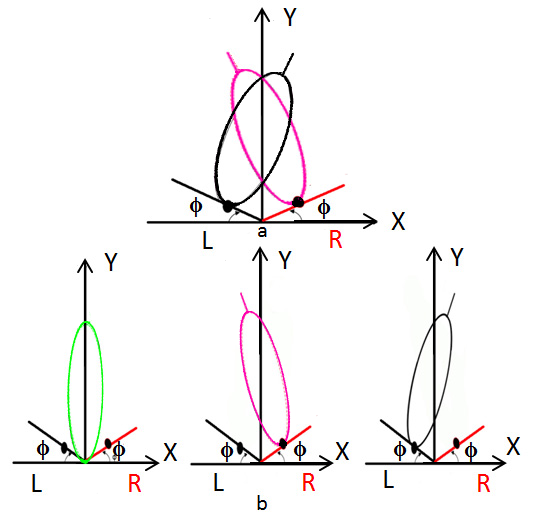 | Figure 1. The geometry of the proposed scanned antenna; a- the two sub-antennas with their patterns, b- the three states of switching the pattern |
2.1. Scanning of the Main Beam
The proposed idea of main beam switching is developed here to gradual scanning of the antenna mainbeam. The idea is analyzed here using array antennas. Figure 2 shows an implementation of the proposed idea, where each of the sub-antennas has the form of a 4-element array. The side element of the two arrays can be assumed common to both arrays. The array factor can be found through finding the path difference between the shown lines and assuming the center element as the phase reference. For a look angle θ with respect to the baseline (X-axis), it can be shown that the array factor due to the two sub-arrays can be given by: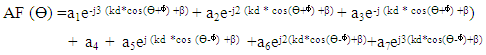 | (1) |
Where d is the element spacing, k=2π/λ is the phase constant, ß is the phase shift between array elements, and a1-a7 are element excitations.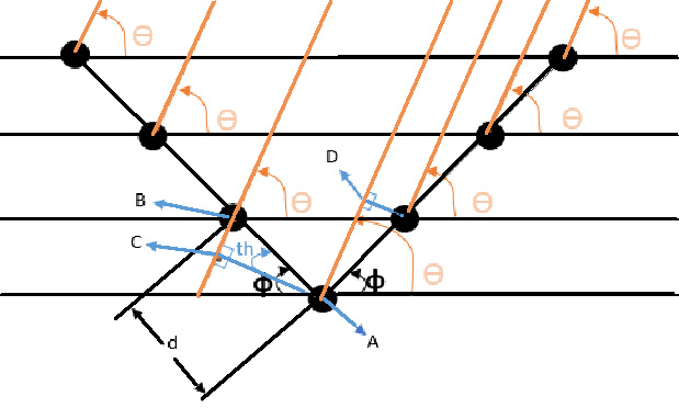 | Figure 2. The geometry of a two 4-element sub-arrays inclined by an angle ɸ to the common baseline |
To implement the idea of amplitude scanning, the amplitudes of the signal supplied to the elements at one side of the antenna is increased by a certain amount while that given to the elements at other side is reduced by the same amount. Thus the excitations of the elements can be arranged as: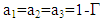 | (2-a) |
 | (2-b) |
 | (2-c) |
The above assumption can be realized by using a power or amplitude dividers for transmitting array, or variable attenuators for receiving arrays. When the amplitude excitation of one side is increased, and that of the other side is reduced by the same amount, the main beam of the radiation pattern will be directed along the normal to the side array which has a larger value of amplitude excitation. Thus the main beam can be scanned as the factor Γ is varied.
3. Results of Computer Simulations
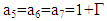
The proposed antenna was investigated by computer simulations. The first case in the computer simulations assumed equal excitations for all elements i.e. ( ai =1, for i =1 to 7) and the tilt angle ϕ was varied from zero to 60°. Figure 3 displays the obtained results which show that for a tilt angle ɸ=0, where the two subarrays are on a straight line forming a conventional linear array, the main beam is along the broad side direction ( along the Y-axis). The magnitude of the main beam is largest when ɸ=0° since the radiated fields of the two sub-arrays add together. As the tilt angle ɸ is increased up to a value just below 20° the main beams of the two sub-arrays still combine into a single beam that is normal to the antenna baseline. However, for angles larger than 20° the main beam splits into two parts; where the left section of the antenna produces a beam directed to the right of the Y-axis, while the right section produces a beam directed towards the left of the Y-axis. The values of the tilt angle ɸ for which there will be beam splitting depends on the width of the sub-main beam corresponding to eachof the two sections of the antenna. For a 4-element uniform array of d= λ/2 spacing, the beamwidth can be shown to be 25°, thus for tilt angles larger than about 20°, the two main beams remain separated. It was found that for a tilt angle ɸ=90°, the subarrays coincides and produces mainbeam along the X-axis, while for larger angles there will be two splitted beams that will merge as the tilt angle goes beyond about 160°. The case of equal excitations of all elements can not offer beam scanning.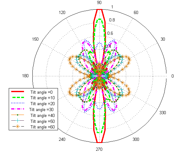 | Figure 3. Normalized patterns of the proposed antenna for tilt angles between 0° and 60°, and equal excitations |
The influences of the tilt angle ϕ and the factor Γ on the resulting radiation pattern were also investigated. Figure 4 shows sample results for Γ=0.5. The main beam is seen to change direction as the tilt angle is varied. Here the left part of the array has excitation of 0.5 while the right section has excitation of 1.5 as stated by Eqs. 2. Similar results were obtained when Γ was given the value of -0.5, but in this case the mainbeam was moving to the left of the Y-axis.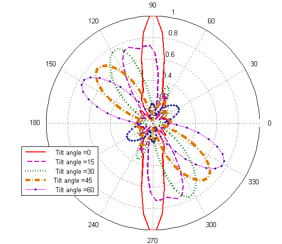 | Figure 4. Normalized patterns for proposed antenna for various tilt angles ϕ when the factor Γ=0.5 |
The variation of the direction of the mainbeam with the tilt angle ϕ is shown in Fig. 5 for various values of the factor Γ. The results show that there is a fair linear relation between the direction of the main beam and the tilt angle ϕ. Better linearity is seen for Γ values larger than zero. When the two subarrays have the same excitations (Γ=0) largest departure from linearity is noticed for small tilt angles and those near 90°. This can be attributed to the overlap of the two mainbeams formed by the two sections of the antenna array. | Figure 5. Variation of the direction of the mainbeam with tilt angle for various values of the factor Γ |
The next set of simulation results were obtained when the element excitations of one antenna section were made not equal to those of the other section. Figure 6 shows the obtained patterns of the proposed antenna with a tilt angle ɸ =15° when the element excitations were set to as given in Eqs. 2 and the factor Г was varied. The factor Γ was increased from zero where the two sub-arrays have the same excitation of unity. When Γ=1 the left sub-array has zero excitation, and the right sub-array will have double the excitation. Figure 6 shows that the main beam has changed direction from the broadside direction to an angle of 15° due to the variation of the factor Г from zero to unity respectively. Thus it can be seen that the mainbeam can be scanned from the normal direction to the antenna baseline to a maximum angle before the mainbeam splits into two parts. This angle is determined by the half power beam width (HPBW) of each of the two subarrays. Scanning of the beam to the right side of the Y-axis can be similarly achieved when the factor Г is given negative values.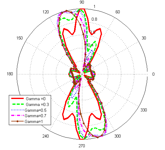 | Figure 6. Normalized patterns for proposed antenna with tilt angle ϕ=15° for various values of the factor Γ |
It can be seen from Fig. 6 that the shape of the mainbeam varies slightly as the beam is scanned. The main beam is a result of a vector sum of two beams due to the two sub-arrays or sub-antennas. As the factor Γ is varied the relative strengths of the two added beams are changed. Thus the resulting mainbeam changes in shape as well as magnitude.Of equal importance is the change in the magnitude of the mainbeam as the mainbeam is scanned by varying the factor Γ. This variation is shown in Fig. 7, where it can be seen that the magnitude of the mainbeam varies by 3.3 dB when the tilt angle ϕ= 15°, while a larger variation of 5.2 dB is noticed for the larger tilt angle of ϕ=30°.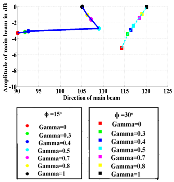 | Figure 7. Variation of the magnitude of the mainbeam with the scan angle for tilt angles; • ϕ= 15° and ♦ ϕ=30° |
3.1. Using two Tilted Half-wave Dipoles
The scanning method was implemented in further simulations where the two elements shown in Fig. 1-a were assumed as half wavelength dipoles as shown in Fig. 8. The value of the separation d was set equal to half wavelength in this simulation. The obtained radiation patterns are shown in Fig. 9 where a tilt angle ϕ= 15° was used and the factor Γ was varied between 0 and 1. The figure shows that the mainbeam direction has moved to the left from the broadside direction and scanned by an angle of about 15°.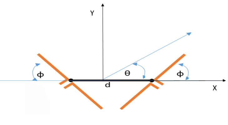 | Figure 8. The proposed scanning implemented on two half-wavelength dipoles |
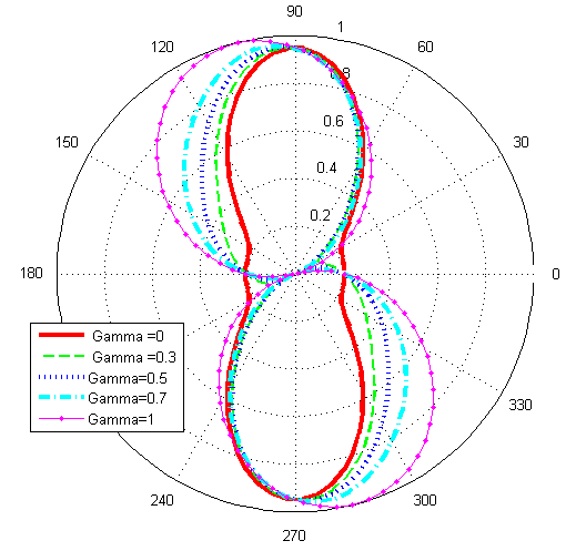 | Figure 9. Normalized patterns for proposed antenna using two dipoles with tilt angle ϕ=15° for various values of the factor Γ |
The results shown in Fig. 10 were obtained when the tilt angle ϕ was set to 30°. The achieved range of the scan is now about 30° to one side of the normal to the array, which is higher than the case of the 4-element subarray that is shown in Fig. 6. The half-wavelength dipole which has HPBW=78° has allowed using larger tilt angle before the appearance of beam splitting. The larger beam width enabled a larger tilt angle that has led to larger scan angle.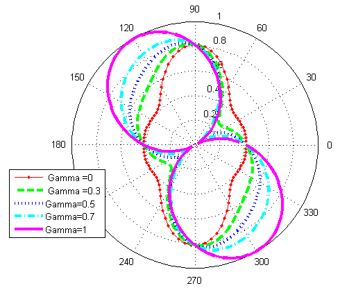 | Figure 10. Normalized patterns for proposed antenna using two dipoles with tilt angle ϕ=30° for various values of the factor Γ |
The variation of the magnitude of the main beam with the scan angle for the antenna using two half-wave dipoles is shown in Fig. 11. It can be seen that the range of variation is less than 1.8 dB for the tilt angle ϕ=30° and less than 0.5 dB for the tilt angle ϕ=15°. These ranges of change are much smaller than those observed for the 7-element array case (Fig. 7).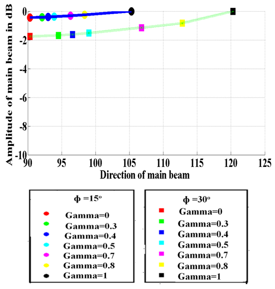 | Figure 11. variation of the level of main beam of the two half-wave dipoles with the scan angle for tilt angle • ϕ= 15° and ♦ ϕ=30° |
4. Conclusions
In this contribution, two similar antennas tilted by a certain angle from a common base-line and are fed through two lines are proposed for beam switching and scanning. By controlling the excitations of the two antennas, the combined main beam can be steered from the normal to one antenna to that of the other antenna. This idea neither requires phase shifters nor frequency scanning. The simulation results showed that the mainbeam can be scanned across ±30° when half-wavelength dipoles are used. The variation in the level of the main beam was less than 1.8dB. The proposed antenna is suitable for many applications that require a simple technique of beam switching or scanning. Modifying the coverage of base-station antenna can be one example.
References
| [1] | R. C. Hansen, "Phased Array Antennas", 2nd Ed., John Wiley, 2009. |
| [2] | R. J. Mailloux," Phased Array Antenna Handbook" 2nd Ed., Artech House, Inc., 2005. |
| [3] | K. Guney, and M. Onay, "Amplitude-Only Pattern Nulling of Linear Antenna Arrays with the use of Bees Algorithm", Progress In Electromagnetic Research, PIER 07, 21-36, 2007. |
| [4] | Sayidmarie, Khalil H., and Baedaa JM Jasem, "Amplitude-only beam scanning in linear antenna arrays", IEEE 7th International Multi-Conference on Systems Signals and Devices, SSD-2010, 2010. |
| [5] | Sayidmarie, K. H., and Saghurchy, M. N.," Array beam Scanning by Variation of Elements Amplitude-Only Excitations", IEEE 4th International Symposium on Microwave, Antenna, Propagation, and EMC Technologies for Wireless, MAPE 2011, 1-3 Nov. 2011, China, PP. 749-753. |
| [6] | Guney, K., and Murat Onay. "Amplitude-only pattern nulling of linear antenna arrays with the use of bees algorithm", Progress in Electromagnetics Research Vol. 70, 2007, PP. 21-36. |
| [7] | Park, Zivin, and Jenshan Lin, "A beam-steering broadband microstrip antenna for noncontact vital sign detection", IEEE Antennas and Wireless Propagation Letters 10 (2011), PP. 235-238. |
| [8] | Tsai, Bingzhang, and Shih-Yuan Chen. "Design of beam-steerable parasitic patch arrays using variable reactive loads", IEEE 4th Asia-Pacific Conference on Antennas and Propagation (APCAP), 2015. |
| [9] | Li, Z., Ahmed, E., Eltawil, A. M., & Cetiner, B. A., "A beam-steering reconfigurable antenna for WLAN applications", IEEE Transactions on Antennas and Propagation, Vol. 63, No. 1, 2015, PP. 24-32. |
| [10] | Li, Z., Israfil Bahceci, and Bedri A. Cetiner, "Broadband beam‐steering reconfigurable antenna", Microwave and Optical Technology Letters, Vol. 59, No. 1, Jan 2017, PP. 63-65. |
| [11] | Khalat, A., et. al., "A 60 GHz Beam-Steering Reconfigurable Antenna", IEEE International Symposium on Antennas and Propagation (APSURSI), 28 June- 1 July 2016, PP. 1279-1280. |

 Abstract
 Reference
 Full-Text PDF
 Full-text HTML