-
Paper Information
- Paper Submission
-
Journal Information
- About This Journal
- Editorial Board
- Current Issue
- Archive
- Author Guidelines
- Contact Us
International Journal of Electromagnetics and Applications
p-ISSN: 2168-5037 e-ISSN: 2168-5045
2017; 7(1): 17-24
doi:10.5923/j.ijea.20170701.03

A Review of Magneto-Optic Effects and Its Application
 Abstract
 Reference
 Full-Text PDF
 Full-text HTML
Taskeya Haider
Faculty of Natural Science, BGMEA University of Fashion & Technology, Dhaka, Bangladesh
Correspondence to: Taskeya Haider, Faculty of Natural Science, BGMEA University of Fashion & Technology, Dhaka, Bangladesh.
| Email: |  |
Copyright © 2017 Scientific & Academic Publishing. All Rights Reserved.
This work is licensed under the Creative Commons Attribution International License (CC BY).
http://creativecommons.org/licenses/by/4.0/

The research activities on the phenomenon of Magneto-optic Effects has recently promulgated due to its versatile use in magneto-optic recordings for high density magnetic data storage, magnetic field sensors and its applications in magneto-electronics. The discovery of magneto-optical effects evoked a new thought that the nature of light was an electromagnetic entity, and played a central role in the contribution of the development of Maxwell's electromagnetic theory. Michael Faraday was at the forefront of discovering this phenomenon, as in 1845 he showed that light interacts with magnetic fields. This study primarily focuses on the understanding of the mechanism of magneto-optic effect by reviewing and critically discussing the rotation of plane of polarization of the light beam as it is transmitted through a magnetized sample, i.e., the Faraday Effect and the rotation of the plane of polarization of a light beam during reflection from a magnetized sample, namely, the Kerr Effect. Relevant theoretical characteristics of these effects and its application in modern technology are also discussed.
Keywords: Magneto-optic Effect, Faraday Effect, Kerr Effect, Polarization, Magneto-electronics
Cite this paper: Taskeya Haider, A Review of Magneto-Optic Effects and Its Application, International Journal of Electromagnetics and Applications, Vol. 7 No. 1, 2017, pp. 17-24. doi: 10.5923/j.ijea.20170701.03.
Article Outline
1. Introduction
- The interaction of light with matter is affected by the magnetic state of the medium and involves the electronic structure of the matter. Such interaction between electromagnetic radiation and magnetically polarized materials results in ‘Magneto-Optic’ effects. These effects played an important role in the early history of electromagnetism, providing an experimental support to the electromagnetic theory of light, as well as to both classical and quantum theory of matter including the motions of electron spin and spin-orbit coupling. In 1845 Michael Faraday discovered that the polarization of a linearly polarized light beam is rotated upon propagating through a media which is placed in a magnetic field parallel to the propagation direction [1, 2]. This experiment was among the firsts, which indicated the intimate relationship between the magnetic field and the light. Moreover, it initiated a research for materials showing optical cross effects, in which the fast manipulation of the light beam in sense of its intensity or its polarization can be realized via external fields. In addition, the Faraday Effect, and its counterpart in reflection, the Magneto-Optical Kerr Effect (MOKE), are widely used to detect the magnetization of materials [3, 4]. The MOKE offers a unique tool for the determination of the surface magnetization of thin films with even higher sensitivity then the Superconducting Quantum Interferometer Devices (SQUID). Nowadays, crystals showing large magneto-optical effects are widely used in optical isolators (Faraday rotators, optical circulators), mode-conversion waveguides and optical data storage [4].
2. Theory of Magneto-Optic Phenomena
- Polarization is one of the most known phenomena supporting the wave character of light. Accordingly, the light is a transverse electromagnetic wave which can be linearly or elliptically/circularly polarized. A linear polarized light is a wave with the electric field vector, E, oscillating along a given direction, perpendicular to the propagation direction (sometimes, this kind of polarization is called plane polarization, the plane of polarization being the plane defined by the direction of the electric field and the direction of propagation). In an elliptically polarized light, the electric field rotates during the propagation, describing an ellipse in a plane perpendicular to the propagation direction (when a circle is described, the wave is called circularly polarized). It can be proven that any linearly polarized wave can be seen as a superposition of two circularly polarized components, namely a left-circularly polarized (LCP) and a right-circularly polarized (RCP) one, of amplitudes EL=ER=E/2. On the other hand, an elliptically polarized light can be seen as a superposition of two linearly polarized components which are out of phase and with different amplitudes (if the electric fields of the two components are equal, the resulting light is circularly polarized). Let’s suppose a linearly polarized light passing through a medium formed by free electrons and fixed positive centres, distributed in such a way to fulfil the local condition of charge neutrality. The linearly polarized wave can be seen as a superposition of the two above mentioned circularly polarized components, LCP and RCP. Obviously, the LCP electric field will drive the electrons into a left circular motion around a fix positive centre whereas the RCP electric field will drive the electrons into a right circular motion (alternatively, the oscillations of the electrons under the influence of the linear polarized light can be decomposed into two opposite circular components). The radius of the circular trajectory is established through the equilibrium of the forces acting on the electron, within the assumption that the pair electron-positive centre forms a rotating electric dipole with an attractive recovering force (imposed by the neutrality condition), Fa, proportional to the radius r, of the circular orbit (Fa=-kr). In the absence of any applied magnetic field, the radii of both orbits of electrons in left and right circular motion are equal, as given by the equation,
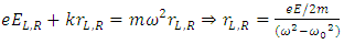 | (1) |
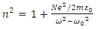
 a material dependant constant (ω>ω0). E is the amplitude of the electric field of the wave and e, the elementary charge. Since the electric dipole moment, Pi, is proportional to the radius of the circular orbit (Pi=eR), it results straightforward from D = εE = ε0E+P with P = NPi (N= number of dipoles per unit volume), that the dielectric constant, ε, can be expressed as:
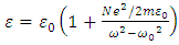 | (2) |
 | (3) |
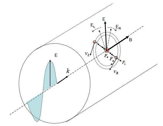 | Figure 1. A Pictorial Representation of Magneto-Optic Effect |
 | (4) |
 | (5) |
 | (6) |
 | (7) |
 | (8) |
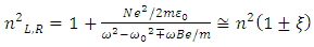
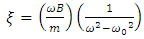
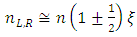
 is still valid in ferromagnetic materials with significant susceptibilities, while the magnetic relative permeability can be further approximated by 1 at optical frequencies (μr (ω) =1), and (ii) the effective Weiss field cannot explain alone the Faraday effect while it is not coupled to the electron motion which ultimately determines the dielectric properties of the material. It was Hulme in 1932 who pointed out that in fact, microscopically, the spin orbit interaction is the one coupling the magnetic moment of the electron with its motion, which in turn responds also to the electric field of the light, connecting thus the magnetic and optical properties of a ferromagnetic material. However, the basic origin of the magneto-optics was quite well understood at the middle of the 20th century and a further significant progress was related especially to a continuous improvement of the experimental techniques and to the macroscopic description related to the general case of magnetic multilayer. Looking in a greater detail to the phenomenological model expressing the linearly polarized light as a superposition of two circularly polarized components, there are actually two processes taking place for the light propagating through a magnetized medium: (i) the two polarized components travelling with different velocities emerge from the media with different phase shifts, leading to the Faraday rotation and (ii) the two components could present different absorption coefficients, leading to different amplitudes of the emergent electric fields, EL and ER, and so, to a given ellypticity of the outgoing light. Hence, the refractive indices nL,R have to be complex parameters and can be expressed by extending eqn. (7) to the case of a complex refractive index, n* = n+ik and by taking into account that the perturbation, ξ of the refractive index via the magnetic field is not dependent only on the magnitude of B, but also on its orientation with respect to the propagation direction, uk = k/k (k is the wave vector in vacuum and uk is its versor). In the general case, ξ can be written as the product Q.uk, where Q is called the Voight vector and is proportional to the field induction B (or magnetization M). It is worth mentioning that in the case with B along uk, ξ = Q and is proportional to B according to relation (6) while relation (7) extents to [6],
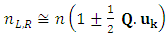 | (9) |
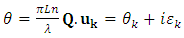 | (10) |
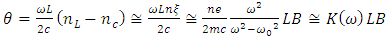
 is the ellypticity of the emergent polarized light. As it can be observed from Eq. 10 it is enough to know the vectors Q and uK (or theirs components), as well as the refractive index and the absorption coefficient of the medium in the absence of the applied field, in order to estimate both θk and
  The most general macroscopic description of magneto-optics is based on the dielectric tensor theory [7] and principally derives from the Maxwell equations of electromagnetic waves propagating in finite magnetic media and a suitable description of the dielectric tensor according to the Onsager relation which postulate that the symmetry of its off diagonal components under a time reversal is kept only by reversing the magnetic field (or magnetization) [8]. Hence,
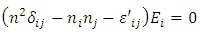
 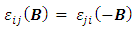 and expending up to linear terms in B, it results (within the assumption that for B = 0 the off diagonal components are zero) that for i ≠ j, each pair of symmetrical components will be proportional to ± components of B. Therefore, the dielectric tensor is expressed as [5, 6, 9],
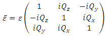 | (11) |
 is the isotropic part of the dielectric constant. There are these diagonal terms, proportional to components of the magnetic field, which modify the light polarization and are responsible for the magneto-optic effects.
3. The Faraday Effect
- Faraday showed that linearly polarized light would undergo a rotation of the plane of polarization upon being transmitted through a medium that has a magnetic field applied along the direction of propagation, as Fig. 2 depicts. Therefore, a longitudinal magnetic field results in the medium becoming optically active [10]. In its simplest form the rotation, ϕ, as expressed in Eq. 12, is proportional to the strength of the magnetic field, B, and the length of the sample, l,
 | (12) |
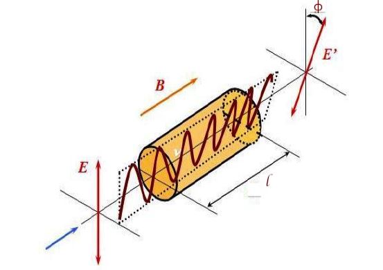 | Figure 2. A Schematic Diagram of Faraday Effect |
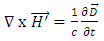
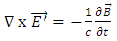
 Maxwell's equations, in the absence of sources, for an electromagnetic wave in a medium are given by (in CGS units):
 | (13) |
 | (14) |
 | (15) |
 | (16) |
 is the electric displacement,
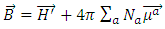
  is the magnetic induction,
  is the macroscopic magnetic field, and
  is the electric field, where the primes are included to distinguish from the application of external electromagnetic fields. The electric displacement and the magnetic induction are related to the induced electric and magnetic moments
  and
and  induced by the electromagnetic wave through the following relations:
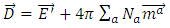 | (17) |
 | (18) |
 | (19) |
 | (20) |
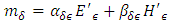
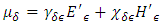
 [13]. Therefore, the polarizability tensors may be written as:
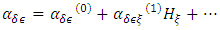 | (21) |
 | (22) |
 | (23) |
 | (24) |
 yields:
 | (25) |

 where ω is the frequency of the incident light upon the medium. Here,
  is the Faraday rotation and
 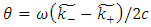 is the ellipticity, nominally referred to as circular magnetic dichroism [13]. Therefore, from the expression given for
  may be written in the following manner,
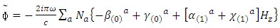 | (26) |
 and
and  are proportional to
  and
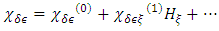
and  the electric and magnetic fields of the incident light, respectively, and are responsible for magnetic optical activity when an external magnetic field is applied. In general, the relations α(0) >>β(0), γ(0), χ(0), α(1)Hz; and α(1) >>β(1), γ(1), λ(1) hold [13]. These relations allow for Eqn. 25 to be approximated as:
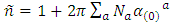 | (27) |
 correspond to the refraction, n, and absorption, k, coefficients, respectively. Furthermore, Eq. 26 shows that the natural optical rotation is given by:
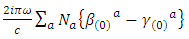 | (28) |
 and
and  are nonzero, resulting in circular dichroism and optical rotation from the real and imaginary parts, respectively [13].In the presence of an applied field, Hz, magnetic optical activity, or a Faraday effect, manifests, in which
  and
and  have roles that are analogous to
  and
and  If a reasonable field strength is applied, then the term
 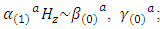 thus, the dominant contributor to the Faraday Effect comes from
  relating to the electric moment of the medium [13]. Historically, it was this interaction that was considered when predictions for the Faraday effect were made, thus ignoring the interaction of the magnetic moment of the medium to that of the magnetic field of the incident light. It was not until experimental data obtained for the Faraday Effect of O2 showed an anomaly, when compared to theoretical predictions, that the magnetic field of the incident light was included.Early quantum mechanical considerations of visible and ultraviolet light propagating through gaseous materials predicted a Verdet constant that varies approximately as the square of the frequency, where
  Generally, the Faraday Effect description reflected H. Becquerel's derived classical expression for the Verdet constant,
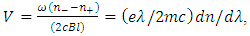 which shows that V is proportional to the dispersion,
  [15]. This describes a change in the index of refraction as a function of wavelength, where, in the long wavelength regime, as shown in Fig. 3, the behaviour of V scales as
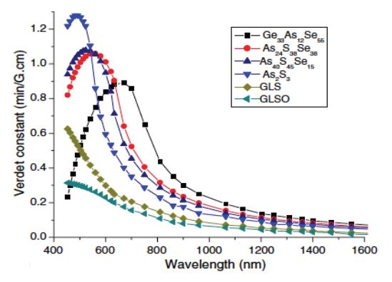 | Figure 3. The Verdet constant for various materials as a function of the wavelength [16] |
 | (29) |
 in which the angular momentum quantum number is
  and
and  is the nuclear spin of the atom [17]. Thus, in terms of the atomic vector polarizability, the Faraday rotation of a propagating beam of linearly polarized light in the z direction through a medium of length l may be expressed as:
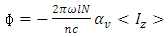 | (30) |
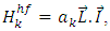
 is satisfied, where Ef and Ei are the final and initial state energies, respectively. An introduction of an external magnetic field, as in the case of the Faraday effect, the energies of the initial and final states may have degeneracies removed, depending upon the angular momentum of each state, resulting in an energy shift for the states, which is the known Zeeman effect. As a result, each state has a different magnetic moment that couples to the external field via
  where
where  is the magnetic moment of state ‘s’. For visualization, consider a system where each atom contains a nondegenerate ground state, with a Zeeman triplet forming excited state, with nuclear spin 0 and no hyperfine structure. This corresponds to a
  transition of an atom, where in an external field, the upper-state level splits with an energy shift
  for the
  states, where
  is the Bohr magneton. Furthermore, when light is incident upon and interacts with the medium, angular momentum must be conserved, and the electric dipole selection rules dictate that only the resonant transitions to higher energy occurs for
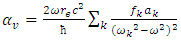
  Right circularly polarized light carries angular momentum of -1, and left circularly polarized light has angular momentum of +1. This results in each circular polarization component interacting with its own two-level system, indicating that each polarization will propagate through the medium with different speeds, and hence different indices of refraction; thus, medium becomes birefringent [18].This description is dominated by the interaction of the medium to the electric field of the incident light and the applied magnetic field, and these theoretical considerations yielded expressions that agreed well with experimental data, except for the Verdet constant of O2 [12]. J. T. Hougen showed that the Verdet constant can be expressed as the sum of two terms:
 | (31) |
 , the triplet ground electronic state, a frequency independent contribution [12]. Vm, therefore, is purely a magnetic contribution that acts as an offset, as Fig. 4 shows.
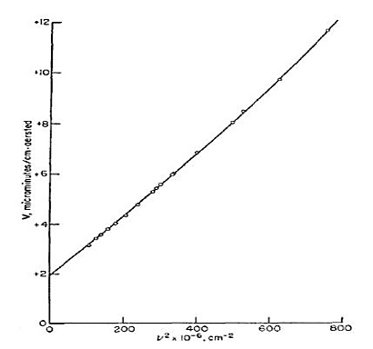 | Figure 4. The Verdet Constant of O2 as a function of the square of the frequency |
 dependence of V was observed. Furthermore, the wavelengths used in this work are far off resonance for both the glass samples used and for the polarized 3He target, which allows for the electric and magnetic polarizability of 3He to be probed. These two effects may be separated through using wavelength dependence; α(1) is wavelength dependent, whereas χ(1) is wavelength independent [12, 19]. Considering the system studied in this work, a collection of polarized 3He nuclei generates volume magnetization that is in addition to the applied external magnetic field that is utilized as a quantization axis for the nuclear spins. Therefore, a Faraday nuclear spin optical rotation is generated by the aligning of the non-zero magnetic moments of the nuclei [17, 20]. This system should then probe a purely magnetic Faraday rotation, namely the gyromagnetic Faraday Effect [19, 21].
4. Magneto-Optic Kerr Effect
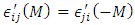
- The Kerr effect was discovered in 1877 [22] It appears when a linearly polarised electromagnetic wave is reflected on a metal surface in presence of an electric or magnetic field (MOKE). The polarization of the reflected wave becomes elliptical and the rotation of the polarization is proportional to both the magnetization M and the thickness of media. Its microscopic origin (Zeeman Effect) is based on the spin-orbit interaction and relativistic effects. [23] We can notice a second effect in the magnetic case corresponding to the Voigt effect, generally ignored as it is very weak. Depending on the direction of M (Fig. 5), there are three geometric configurations of MOKE: polar, longitudinal, transverse. We must know that generally the observed effect is the superposition of the three MOKE modes. These effects are greater for materials with a particular symmetry which is reflected in the form of its dielectric tensor. The properties of the dielectric tensor come from thermo statistic and is Hermitian in the absence of absorption in a magnetic medium. [2]
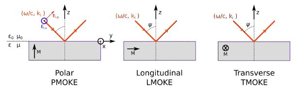 | Figure 5. Three geometries of MOKE |

 We introduce the electric displacement D and the magnetic induction B linked to the magnetic field H:
 | (32) |
 | (33) |
 and μ are the tensorial permittivity, relative permittivity and permeability respectively. The permeability at optical frequencies is close to the vacuum permeability μ0 for magnetic and non-magnetic media (Landau hypothesis) [2]. Thus, we assume that
  where δ is the Krönecker symbol. Assuming that the medium is electrically neutral, Maxwell equations give us:
 | (34) |
 Defining an effective permittivity by
  eqn. 34 derives:
  | (35) |

 | (36) |
 . In PMOKE situation with z-axis collinear to M, the permittivity tensor is:
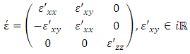 | (37) |
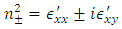 (assuming nx = 0 and ny = 0). The Eigen modes are found by replacing these eigenvalues in Eq. 36 and then, it can demonstrated that
 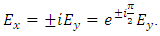 This means that there are two waves present with a circular polarization (left and right-handed), propagating with the index n+ and n-. The induction is,
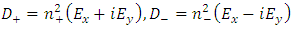 | (38) |
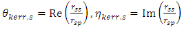
 for s and p of reflected field Er, are calculated with incident field Ei and the boundary conditions on the interface. s or p denotes polarization when the electric field of the light is orthogonal or parallel to the plane of incidence. Starting from:
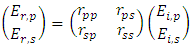 | (39) |
 | (40) |
 | (41) |
5. Applications of Magneto-Optic Effect
- Although MO effects are known for at least 175 years, their practical applications are recent and the majority of them only appeared in the three last decades. This is explained by the necessity to measure the light properties with high precision. The most common applications are:• determination of the average free carrier effective mass [25];• detection of magnetic impurities;• dynamic studies of film growth;• MO filters as atomic line filters;• MO devices: MO memories, MO magnetic field sensors, MO modulators, and integrated optoelectronic devices, like optical circulators, isolators and switchers;• Magneto-optical drives using thermomagnetic recording and MO sensing of recording information, with a minimum of 50 years of shelf life;• MO microscopy;• Spintronics.Spintronics or magneto-electronics is a recently emerged field that combines small scale magnetic elements with conventional semiconductor electronics, to obtain devices with new or enhanced functionality [26]. This new technology exploits both the intrinsic spin of the electron and its associated magnetic moment, in addition to its fundamental electronic charge, in solid-state devices. The advantages of spintronic devices are magnetic sensors, non-volatility, increased data processing speed, decreased power consume, and increased transistor density compared with conventional semiconductor devices [26]. Within this field of research, Dilute Magnetic Semiconductors (DMSs), are especially important materials. In these materials, rare earth or transition metal ions replace a considerable number of the native ions in the semiconductor’s lattice [27, 28]. This offers opportunities for new generation of devices combining standard microelectronics with spin-dependent effects that arise from the interaction between the spin of the carrier and the magnetic properties of the material [29].Most of the devices in spintronics made so far are based on metallic thin films, but it is not easy to couple them to conventional semiconductors because of the very large resistance mismatch. A ferromagnetic semiconductor could be integrated with standard semiconductor technology. It is anticipated that if ferromagnetism and electronic transport could be coupled in semiconductors, the effect of magnetism would be significantly stronger than the phenomena observed in metals [29]. The emerging field of semiconductor spintronics seeks to exploit the spin of charge carriers in semiconductors. It is widely expected that new functionalities for electronics and photonics can be derived if the injection, transfer, and detection of carrier spin can be controlled above room temperature. Among this new class of devices are spin transistors operating at very low power, optical emitters with encoded information through their polarized light output, fast non-volatile semiconductor memory, and integrated magnetic/electronic/photonic devices (electromagnetism-on-a-chip) [29]. Several techniques can be used in the detection of the electrons spin like, MO effects, ballistic spin filtering, and nonlocal spin valve [30]. The last two are only used in spintronics devices, while MO effects are also suitable to laboratorial studies on DMSs.
6. Conclusions
- The discovery of magneto-optic effect in 1945 by Michael Faraday marked the first observation of an interaction between light and magnetism, as well as the beginning of the field of magneto-optics. Faraday's findings were further expanded upon when in 1876 John Kerr discovered the corresponding effect in the reflection of polarized light from the pole of a magnet. An introduction into magneto-optical effects shows that the phenomenon arises from the different interactions of the magnetized medium to right and left-handed circularly polarized light. Linearly polarized light, however, with a given plane of polarization, may be expressed as the superposition of two circularly polarized components, that is, it is a decomposition of right-handed and left-handed circularly polarized waves. The Kerr effect may also result in the reflected light wave becoming elliptically polarized, but unlike reflection from a non-magnetized surface, the plane of polarization may also undergo a rotation. A Kerr effect is manifested as a change in polarization or in the intensity of light that is reflected from the surface of a magnetized medium, the size of which depends upon the material, the saturation magnetization of the surface domains, the wavelength of the incident light, and the angle of incidence. Thus, a Kerr effect may be applied to any metallic magnetic material with a sufficiently smooth surface. The underlying description for the Kerr effect, as well as the Faraday Effect, lies in the dielectric tensor, which determines the optical properties of a medium by the motion of the electrons. When a sample has a surface magnetization, off- diagonal terms arise in the dielectric tensor, which ultimately causes the magneto-optical phenomenon.