Charles U. Ndujiuba, Oluwafemi A. Ilesanmi, Oboyerulu E. Agboje
Electrical and Information Engineering Department, Covenant University Ota Nigeria
Correspondence to: Charles U. Ndujiuba, Electrical and Information Engineering Department, Covenant University Ota Nigeria.
| Email: |  |
Copyright © 2017 Scientific & Academic Publishing. All Rights Reserved.
This work is licensed under the Creative Commons Attribution International License (CC BY).
http://creativecommons.org/licenses/by/4.0/

Abstract
In this paper, conventional inset-fed rectangular patch antenna was designed, simulated, analyzed and modified in other to improve on its bandwidth. Patch antennas inherently have narrow bandwidth, which makes them have restricted areas of application. In other to enhance this narrow bandwidth, this paper combines the use of both the partial ground method and edge-cut techniques of bandwidth enhancement to increase the bandwidth of the designed inset-fed conventional rectangular patch antenna from 80MHz to 180MHz. It was noted that other antenna parameters like: the return loss, voltage standing wave ratio (VSWR), and the gain were equally improved on. This technique also ensures that the size of the antenna is equally reduced to make it suitable for integrated circuit, portable and mobile wireless communication applications. High frequency structure simulator (HFSS) software was used for the design and simulation the result of this project shows that by using partial ground with edge-cut of patch, better bandwidth and performance improvement can be achieved from a patch antenna. The designed antenna is good for the middle band WiMAX technology. WiMAX has three allocated frequency bands: Low band is between (2.5-2.69) GHz, the middle band is between (3.2-3.8) GHz and the upper band is (5.2-5.8) GHz.
Keywords:
Patch Antenna, Inset feed, Bandwidth, Edge-cut, Partial ground
Cite this paper: Charles U. Ndujiuba, Oluwafemi A. Ilesanmi, Oboyerulu E. Agboje, Bandwidth Enhancement of An Inset-Fed Rectangular Patch Antenna using Partial Ground with Edge-cut Method, International Journal of Electromagnetics and Applications, Vol. 7 No. 1, 2017, pp. 9-16. doi: 10.5923/j.ijea.20170701.02.
1. Introduction
In a wireless communication system, antennas are very essential. An antenna can be defined as a device which radiates and receives electromagnetic energy efficiently and in a desired manner. In other words, an antenna can also be seen as a transformer which transforms electrical signals into electromagnetic waves or converts electromagnetic waves back into electrical signals. Demands for antennas with conformal structure for airborne systems, small size and multiple functions coupled with increased bandwidth requirements have resulted to high degree of exploitation of printed antennas or other slot type antennas with the aid of powerful computational software for its design and simulation before realization.Microstrip antennas have a lot of advantages which make mobile communication industry operators preferre them to the conventional antennas for mobile to satellite communications, cellular, GPS, satellite, wireless LAN for computers Wi-Fi, Bluetooth technology, Radio Frequency ID devices, WiMAX, and so on. Future needs in the field of wireless mobile communication such as high bandwidth, antenna arrays for improved efficiency, portable mobile communication devices and information and monitoring gathering devices, have attracted the attentions of many researchers in the field of communication engineering to embrace the design and analysis of various shapes of microstrip patch antenna for improved bandwidth and other antenna parameters to suit their needs.
2. Review of Past Works on Bandwidth Improvement
One of the major disadvantages of patch antennas is the narrow bandwidth typically 3-6% of the operating frequency [1]. Various researchers have carried out different research work on some ways of improving the bandwidth of a patch antenna. This in a way involves modifying some parts of the patch antenna structure, using different feed techniques or even stacking the antenna.Some of this methods and works include the use of a partial ground for a rectangular patch antenna. According to [2], using a partial ground, that is reducing the dimension of the ground plane improves the bandwidth by about 30%, while still reducing the return loss (indicating better impedance matching) of a rectangular patch when compared to the one with full ground.Also according to [3], bandwidth of a patch antenna can be improved upon by loading two square shape slots along the side surface of a rectangular patch antenna. It was observed that this method also improved the bandwidth by about 25%. According to [4], bandwidth of a rectangular patch antenna can also be improved on by stacking. That is multiple patch antennas are stacked together to achieve a bandwidth improvement of 30%. One of the short comings of the method is increased size of the antenna, making it unsuitable for portable or mobile communication devices.
3. Designing an Inset-Fed Rectangular Patch Antenna
In this paper, a thin medium dielectric substrate like FR4 with dielectric constant, εr = 4.4, for size reduction and appropriate feed technique was used to enhance good input impedance matching (inset feed). HFSS software was used for the design, simulation and analysis. HFSS is a full wave finite element high frequency electromagnetic field simulator, with good standard accuracy. HFSS is actually good because its results are very close to experimental results and gives more insight into the available structure. There are three basic design parameters to be considered when designing a rectangular patch antenna. These are: the operating frequency (fo), the dielectric constant (εr) of the substrate and the thickness or the height of the dielectric substrate (h). When these three parameters are pre stated, then the transmission line model can be used to design the antenna by following the steps below:Determining the width of the patch: the width W is calculated using [5, 6]: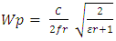 | (1) |
Where, c is the speed of light in free space = (3x10⁸m/s)and  | (2) |
Le being the effective length of the patch and is given as  | (3) |
Next is to calculate the effective dielectric constant: 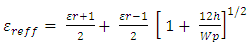 | (4) |
Where εr is the dielectric constant of the substrate and  is the effective dielectric constantNext is to calculate the effective length, which is given as
 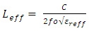 | (5) |
Next step is to determine the extended length of the patch due to the fringing field and it’s given as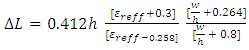 | (6) |
The real length of the patch is given as: 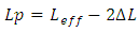 | (7) |
To determine the ground plane dimensions length (Lg) and width (Wg)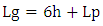 | (8) |
 | (9) |
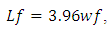
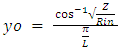
Feed point Location of an Inset Fed Rectangular Patch (xo, yo, wf, Lf).There are different methods of feeding a patch antenna like: probe feed, microstrip line feed, aperture coupled feed and proximity coupling feed. But of all, microstrip line feed and the coaxial probe feed are commonly used because of their simplicity.Microstrip inset feed method was used in this design for proper input impedance matching. The line parameters were designed using a standard input impedance of 50Ω [7]. Feed point location where input impedance is approximately 50Ω can be calculated using [8-11]. | (10) |
where, | (11) |
 | (12) |
 | (13) |
 | (14) |
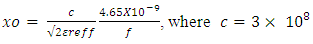
Using Matlab code, the require dimensions of the patch, the ground and the inset feed points were calculated and the design and simulation of the inset fed conventional and modified patch antennas was carried out using HFSS software are as shown in the figures below; 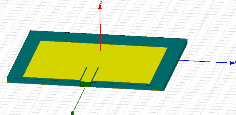 | Figure 1. Conventional inset fed Rectangular Patch Antenna (Top view) |
 | Figure 2. Conventional inset fed Rectangular patch Antenna (Bottom View) |
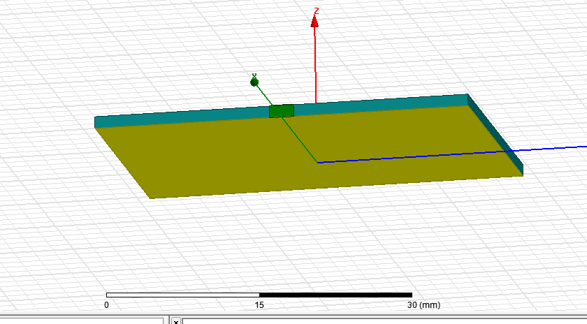
 | Figure 3. Modified Inset Fed Rectangular Patch Antenna (Top view) |
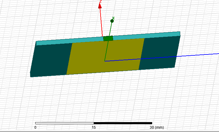 | Figure 4. Modified Inset Fed Rectangular Patch antenna (Bottom View) |
4. Simulation Results and Analysis
In engineering research work, simulation and results are very important as it gives us an insight into the performance of the designed object and so making the performance predictable before realization. The figures below show simulated responses of the conventional and modified patch antennas.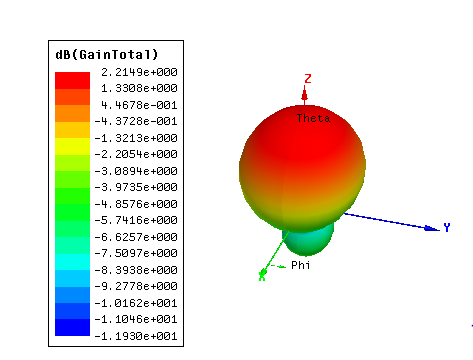 | Figure 5. Total Gain dB plot for the inset fed conventional patch antenna |
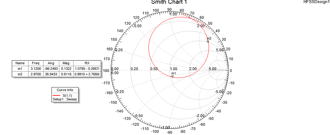 | Figure 6. Smith chart for the inset fed conventional patch antenna |
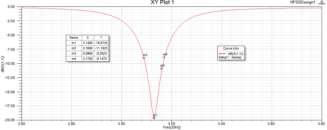 | Figure 7. Retun loss (S11 plot) for the inset fed conventional patch antenna |
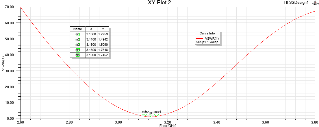 | Figure 8. Voltage Standing Wave Ratio (VSWR) Plot for the inset fed conventional patch antenna |
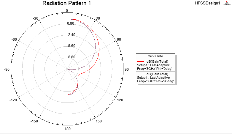 | Figure 9. Radiation pattern (Phi) for the inset fed conventional patch antenna |
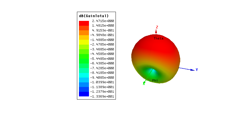 | Figure 10. Total gain dB plot for the inset fed modified patch antenna |
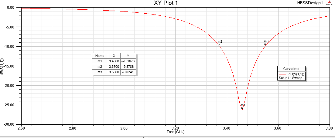 | Figure 11. Return loss for the inset fed modified patch antenna |
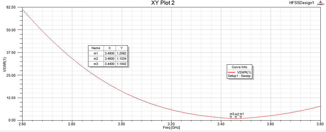 | Figure 12. VSWR for the inset fed modified patch antenna |
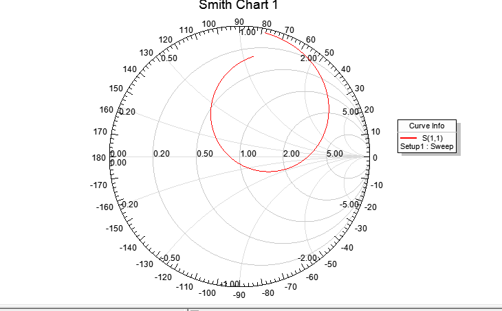 | Figure 13. Smith chart for the inset fed modified patch antenna |
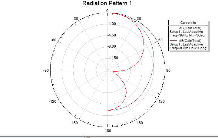 | Figure 14. Radiation pattern (Phi) for the inset fed modified patch antenna |
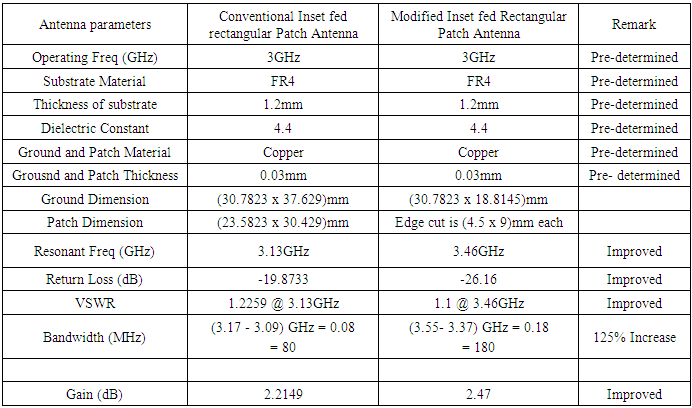
From the plots, return loss for the conventional patch antenna at the resonant frequency of 3.13GHZ is - 19.8733dB and the VSWR is 1.2259, showing that the antenna was properly matched. The bandwidth of the conventional inset fed rectangular patch antenna as shown in the plot is 80MHz around the center frequency. That is (3.09GHz - 3.17GHz) The Gain is 2.2149dB and the radiation pattern is good. Also from the plots for the modified inset fed rectangular patch antenna, it is can be seen that the return loss has improved to -26.16dB and the VSWR to 1.1. This result shows that there was a better input impedance matching here as the VSWR tends to 1, at the resonant frequency and therefore little or no energy is reflected back from the antenna. The bandwidth of the antenna has also increased to 180MHz around the center frequency that is (3.37GHz - 3.55GHz). This frequency range is good for WiMAX medium range application. There is also a noticeable increase in the Gain of the modified antenna.
5. Conclusions
In this paper, the disadvantage of low bandwidth of a rectangular patch antenna, was addressed using modified shape of ground and radiating patch (combination of partial ground method and slots at the four edges of the patch) to achieve an improved bandwidth of 125% of that of the conventional rectangular patch with an inset feed technique, to achieve a better impedance matching.The modified antenna resonates at 3.46GHz and has a bandwidth of (3.37GHz – 3.55GHz) which is good for the middle band WiMAX (Worldwide Interoperability for Microwave Access) system technology.There were also noticeable improvements on other antenna parameters such as the Gain, Return Loss, VSWR and radiation pattern from the simulation result plots as show in the table below.Table 1. Designed Conventional and Modified antennas Parameter and simulation result table
 |
| |
|
Also for most mobile and hand held communication devices where patch antennas are being used, small sizes are desired. In this work, in addition to the improved antenna parameters through the use of defected ground and modified shape, the size of the antenna has also been reduced considerably therefore making it suitable for mobile and portable hand held applications.From the simulation result got from this project, it is clear that by using partial ground with edge cut of patch, better bandwidth and performance improvement can be achieved from a rectangular patch antenna.
References
| [1] | Milligan, Thomas A. Modern Antenna Design. s.l.: Wiley-IEEE Press, 2005. |
| [2] | Suhana Rashid, Chandan Kumar Chakrabarty "Bandwidth Enhanced Rectangular Patch Antenna Using Partial Ground Plane Method For WLAN Applications". Putrajaya Campus: Universiti Tenaga Nasional, 2015. The 3rd National Graduate Conference. |
| [3] | Patil, "Enhancement of Bandwidth of rectangular Patch Antenna using two square slots techniques" 2012, International Journal of Engineering Sciences & Emerging Technologies. volume 3, Issue 2, pp. 1-12. |
| [4] | Shiva Chauhan, P.K. Singhal, "Enhancement of Bandwidth of ectangular Patch Antenna Using Multiple Slots in The Ground Plane", 2014, International Journal of Research in Electronics and Communication Technology. Vol. 1, Issue 2. |
| [5] | P.A. Nawale, Prof. R.G. Zope "Rectangular Microstrip Patch Antenna For 2.4 GHz Communication Using Defected Ground Structure" 2015, International Journal of Advance Foundation and Research in Computer. |
| [6] | Balanis, C.A. Antenna Theory analysis and Design. canada : John Wilet& sons, 2005. |
| [7] | Nita Kalambe, Dhruv Thakur, Shubhankar Paul. "Design of Microstrip Patch Antenna for Wireless Communication Devices". 2015, International Journal of Science and Research. |
| [8] | Choudhury, Suvadeep "Effect of Dielectric permittivity and height on a Microstrip Fed Rectangular patch antenna." 2014, Interntional journal of Electronics & communication Technology, pp. 1-2. |
| [9] | M.A Martins, A.I. Sayeed. "A design rule for Inset fed Rectangular Microstrip Patch Antenna"' 2010, WSEAS Transactions on Communications. |
| [10] | Charles U. Ndujiuba, Adebiyi A. Adelakun, Oboyerulu E. Agboje." Hybrid Method of Analysis for Aperture-Coupled Patch Antenna Array for MIMO Systems" International Journal of Electromagnetics and Applications 2015, 5(2): 90-97 DOI: 10.5923/j.ijea.20150502.03. |
| [11] | Charles U. Ndujiuba1, Adetokunbo O. Oloyede "Selecting Best Feeding Technique of a Rectangular Patch Antenna for an Application" International Journal of Electromagnetics and Applications 2015, 5(3): 99-107 DOI: 10.5923/j.ijea.20150503.01. |

 Abstract
 Reference
 Full-Text PDF
 Full-text HTML