-
Paper Information
- Paper Submission
-
Journal Information
- About This Journal
- Editorial Board
- Current Issue
- Archive
- Author Guidelines
- Contact Us
International Journal of Electromagnetics and Applications
p-ISSN: 2168-5037 e-ISSN: 2168-5045
2016; 6(3): 51-57
doi:10.5923/j.ijea.20160603.01

Constant False Alarm Rate for Target Detection by Using First Order and Second Order Microwave Differentiators
 Abstract
 Reference
 Full-Text PDF
 Full-text HTML
Srinivasa Rao Sankranti1, Tirumala Krishna Battula2, Malleswara Rao Veera1
1Dept. of ECE, GITAM University, Rushikonda, Visakhapatnam, Andhra Pradesh, India
2Dept. of ECE, UCEV, JNT University Kakinada, Vizianagaram, Andhra Pradesh, India
Correspondence to: Srinivasa Rao Sankranti, Dept. of ECE, GITAM University, Rushikonda, Visakhapatnam, Andhra Pradesh, India.
| Email: |  |
Copyright © 2016 Scientific & Academic Publishing. All Rights Reserved.
This work is licensed under the Creative Commons Attribution International License (CC BY).
http://creativecommons.org/licenses/by/4.0/

The main objective of this paper is to detect a target in marine RADAR by persevering constant false alarm rate using first order and second order microwave differentiators. In existing detection, conventional differentiators, which are made with R & C components were used. By using this RC differentiator, the display system of the target detecting RADAR was overwhelmed as they are having less gain. So the target may be undetected even though its strength is high. By using these microwave differentiators, the display system of the RADAR can be increased. The simulations are carried out using ADS environment.
Keywords: Fast Time Constant (FTC), Microwave Differentiator, Constant False Alarm Rate (CFAR), Clutter, Micro strip, ADS (Advanced Design Software) etc
Cite this paper: Srinivasa Rao Sankranti, Tirumala Krishna Battula, Malleswara Rao Veera, Constant False Alarm Rate for Target Detection by Using First Order and Second Order Microwave Differentiators, International Journal of Electromagnetics and Applications, Vol. 6 No. 3, 2016, pp. 51-57. doi: 10.5923/j.ijea.20160603.01.
Article Outline
1. Introduction
- In order to find the time derivative of the incoming signal Digital Differentiators [1-3] are used. The considerable drawback of these digital diffrentiator is that they can work efficiently upto 500MHz. D.C. Chang and C.W. Hsue [4] explains the design and implementation of digital filters at microwave frequencies by using transfer functions in the Z domain. Chin-Wen Hsue, Lin-Chuan Tsai and Kuo-Lung Chen, [5, 6] describe the implementation of first order and second order Microwave Differentiators by using bilinear transformation method. S.S.Rao et.al [7] proposed a method of designing a first order differentiator at microwave frequencies by converting the transfer function which is in z-domain to S-domain [8] by using the transformation techniques. G. V. Weinberg [9] explains how Pareto distribution can be used as a model for all grazing angle scenarios. K. J. Sangston et.al [10] explains detecting a radar target signal against correlated non-Gaussian clutter, which is modeled by the compound-Gaussian distribution.The microwave differentiators are used [11] in target detection of marine RADAR applications. The tracking computers are used to detect the radar signal and extract the target information enclosed in that signal. The tracking computers cannot detect it, if the radar signal is displayed along with the clutter. Generally, this happens, if the tracking computers are overloaded.The paper is organized as follows:Section 2 deals about Log FTC receiver and design of FTC circuit by using R&C components. Section 3 deals with FTC circuit implementation using first & second order Microwave differentiator and comparsion of the same. Results and conclusions are discussed in Section 4.
2. Design of FTC Circuit by Using R &C Components
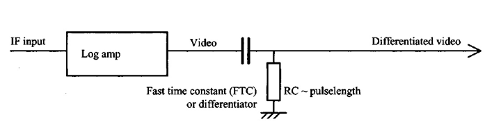 | Figure 1. FTC Circuit |
3. FTC Circuit Implementation by Using First Order and Second Order Microwave Differentiator
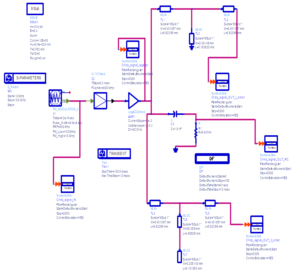
- The traditional differentiator which was formed with RC components is replaced by the first order and second order microwave differentiator which is formed with micro strips is as shown in figure 5 and figure 7.
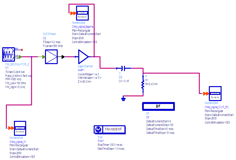 | Figure 2. FTC Circuit implementation in ADS Software (by using RC components) |
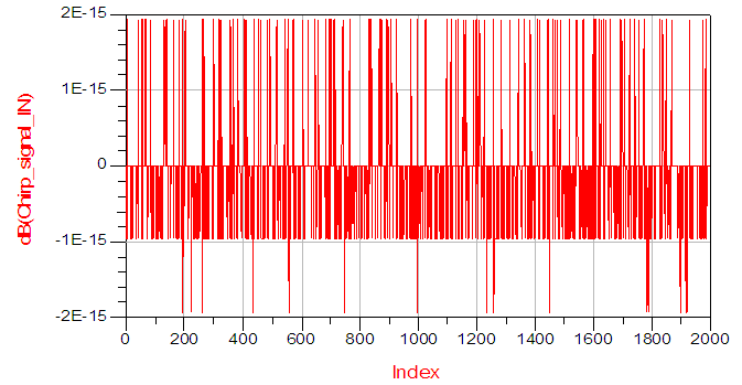 | Figure 3. Chirp input signal |
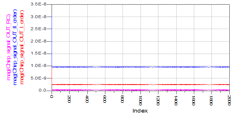
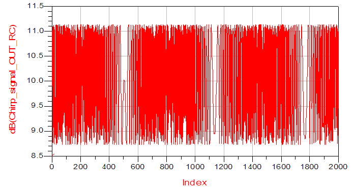 | Figure 4. FTC output by using RC components |
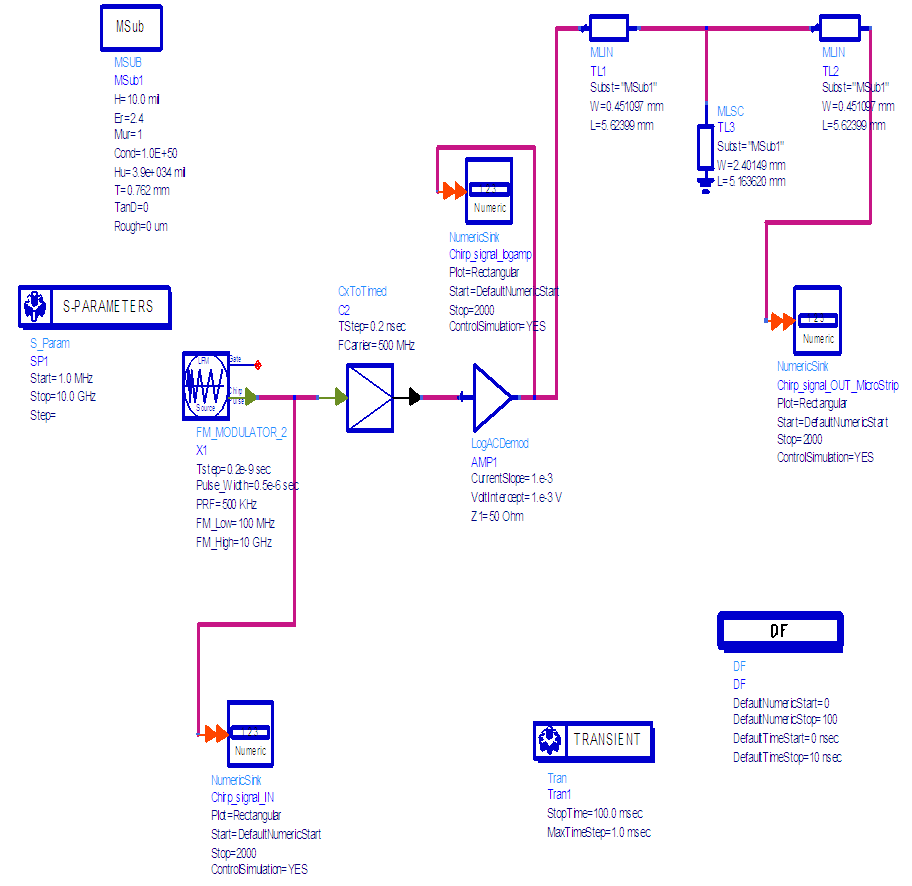 | Figure 5. FTC circuit implementation using First Order Microwave differentiator |
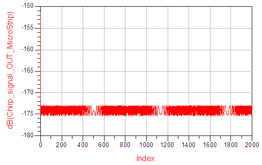 | Figure 6. FTC output by using first order microwave differentiator |
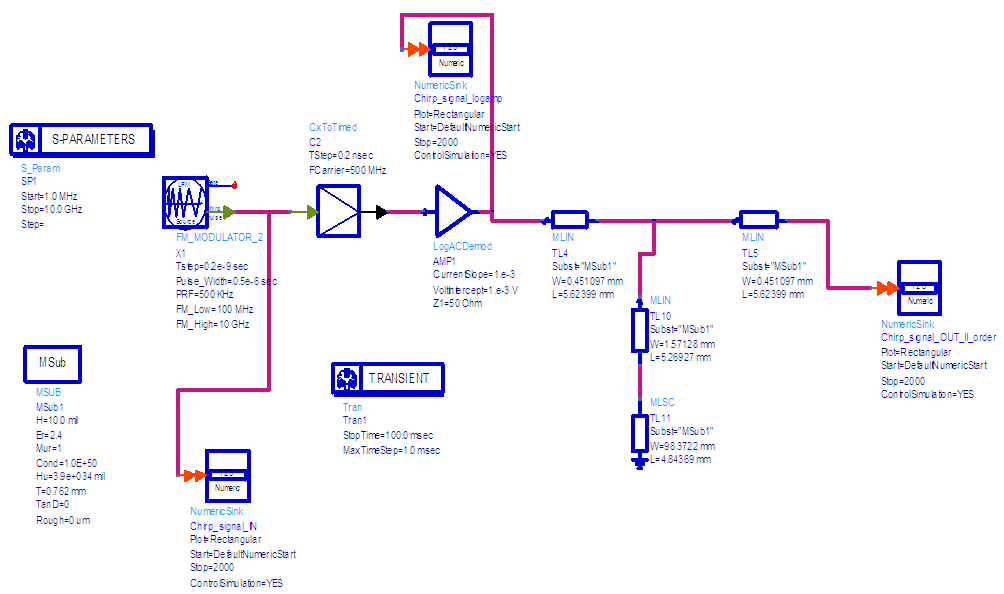 | Figure 7. FTC Circuit using Second order Microwave differentiator |
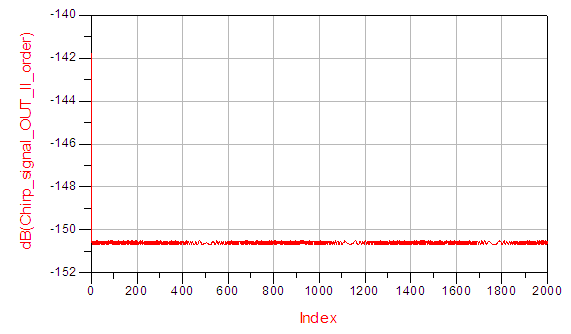 | Figure 8. FTC Circuit output using Second order Microwave differentiator |
 | Figure 9. Comparison of all there FTC circuits |
 | Figure 10. Magnitude Comparison of all three FTC circuits |
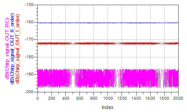 | Figure 11. Variation of gain in dB of all three FTC circuits |
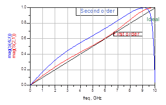 | Figure 12. Magnitude response Microwave differentiators |
4. Results and Conclusions
- A differentiator, which is set by using basic components like capacitor (C) and resister (R) as shown in fig 1.The same circuit is performed in Advanced Design Software (ADS) as shown in fig 2 and the input is applied by using chirp signal generator. The output of the circuit is shown in figure 4. By observing the output, the clarity of the signal is not good, i.e the gain is less. So as the gain is less, eliminating the mean value of the clutter is difficult. Even a small increases in background clutter could result in excessive false alarms that overload the capacity of the tracking computer. So there is a probability of missing the target.RC Differentiator circuit is replaced with first order microwave differentiator which is made of micro strip lines as shown in fig 5. The output for the same circuit is shown in figure 6. By examining the output, the clarity of the signal is good when compared to RC differentiator, i.e the gain is high when compared to RC differentiator. As the gain is increased by 12dB, removing the mean value of clutter is easy when compared to RC Differentiator. So the tracking computer is less overloaded as CFAR works better. So there is less chance of missing the target.RC Differentiator circuit is replaced with second order microwave differentiator which is made of micro strip lines as shown in fig 7. The output of the same is shown in fig 8. By studying the output, the clarity of the signal is very good when compared to RC differentiator & first order microwave differentiator, i.e the gain is increased by 28dB and 16dB respectively. As the gain is very high, removing the mean value of clutter is very easy when compared to RC Differentiator & first order microwave differentiator. So the tracking computer is very less overloaded as CFAR working in best way. So there is very less probability of missing the target. The comparison of all three differentiators is shown in fig 9 and the same magnitude response output is shown in fig 10 and gain in dB is shown in fig 11. The magnitude response of microwave differentiators which are shown in fig 12 are same as the magnitude response of digital differentiators.