-
Paper Information
- Paper Submission
-
Journal Information
- About This Journal
- Editorial Board
- Current Issue
- Archive
- Author Guidelines
- Contact Us
International Journal of Electromagnetics and Applications
p-ISSN: 2168-5037 e-ISSN: 2168-5045
2016; 6(2): 42-50
doi:10.5923/j.ijea.20160602.03

Compact Design of Dual-band Fractal Ring Antenna for WiMAX and WLAN Applications
 Abstract
 Reference
 Full-Text PDF
 Full-text HTML
Dhirgham K. Naji
Department of Electronic and Communications Engineering, College of Engineering, Al-Nahrain University, Baghdad, Iraq
Correspondence to: Dhirgham K. Naji, Department of Electronic and Communications Engineering, College of Engineering, Al-Nahrain University, Baghdad, Iraq.
| Email: |  |
Copyright © 2016 Scientific & Academic Publishing. All Rights Reserved.
This work is licensed under the Creative Commons Attribution International License (CC BY).
http://creativecommons.org/licenses/by/4.0/

This paper proposes a new design approach for dual-band coplanar waveguide (CPW)-fed pentagonal ring fractal patch antenna (PRFPA) which generates two wide resonant frequency bands for -10-dB S11 bandwidth to cover 3.5-GHz WiMAX and 5.5-GHz WLAN simultaneously. To achieve dual-band operation, a first-iterative fractal-radiating patch is printed on a single substrate layer and a CPW structure is used to feed this antenna. For numerical analysis, optimization, and electromagnetic (EM) modeling of the prototype structure, CST MWS is used. To assess the antenna performance in terms of impedance bandwidth, radiation pattern, realized peak gain, and efficiency, ANSYS HFSS is employed. Simulation results obtained from the two softwares, having different numerical techniques, are in close agreements, and validate the design principle. The simulation results show that PRFPA has a compact size  , planar, simple design and low-cost to be manufactured. In addition, the proposed antenna operates in dual band, it has good stable omnidirectional radiation patterns, and the peak realized gain over the operating bands are 2.04 and 3.44 dB, respectively.
Keywords: Coplanar waveguide (CPW), Compact, Dual-band, Pentagonal ring fractal antenna
Cite this paper: Dhirgham K. Naji, Compact Design of Dual-band Fractal Ring Antenna for WiMAX and WLAN Applications, International Journal of Electromagnetics and Applications, Vol. 6 No. 2, 2016, pp. 42-50. doi: 10.5923/j.ijea.20160602.03.
Article Outline
1. Introduction
- Due to the tremendous increasing in modern communication technologies and with the rapid demand for different wireless frequency applications on a single wireless terminal device, compact dual- and multi-band planar antennas are the best solution. Over the past decades, there exist numerous designs of the dual-band planar antennas that based on microstrip technology and have been reported for wireless communications, especially for 3.5-GHz WiMAX (3.3–3.7 GHz), 5.5 GHz (5.150–5.825 GHz) and/or 2.4GHz (2.4–2.483 GHz) WLAN applications [1-7]. These include inverted-F antenna (IFA) structure [1, 2], microstrip line-fed split ring metamaterial structure [3], multiple circular arc-shaped strips with binomial curved conductor-backed plane [4], microstrip line-fed stacked patch antenna [5], multistrip monopole antenna with defected ground structure [6], toothbrush-shaped patch, a meander line, and an inverted U-shaped patch [7]. However, most of these antennas are large in size. Alternatively, asymmetric coplanar strip (ACS)-fed monopole antennas [8-11] have been employed to design compact-size dual-band antennas for WLAN and WiMAX wireless applications. Despite of ACS-fed antennas are capable of providing dual-band with compact size, their radiation patterns are not symmetrical since the ACS-fed structure has an unbalanced nature [10].Among feeding structures used for dual-band antennas, the coplanar waveguide (CPW) [12-18] is very attractive by researchers due to its attractive features, such as low profile, low cost and better isolation from feeding networks. In addition, the CPW provides the benefits of good impedance matching, omnidirectional patterns, minimum surface wave and it is easy of fabrication comparing to other excitation methods, e.g. coaxial probe- and microstrip line-fed lines [19]. Thus, based on the aforementioned features of CPW feeding technique, the CPW is adopted here in the design of the proposed antenna.In general, antennas can operate in different frequency bands by adding and/or modifying either to their radiating patch resonator elements of several distinct lengths depending on the lowest resonance frequency band or etching slots in the ground plane [20]. Although, these antennas have generated multi-band for different applications, but most of them are too complex for the practical applications. Moreover, these antennas result in drawbacks, namely; the use of resonator elements for generating different resonance modes may increase the size of these antennas; mutual coupling among signal paths of different resonator parts; complex fabrication process. Thus, due to the above aforementioned drawbacks of the loading resonator based-technique for dual- and multi-band antenna operation, these antennas are not suitable to use in the case of restricted available terminal space.Due to the well-known interesting features, self- similarity and space filling, fractal geometries have intrinsic features as compared with traditional Euclidian counterparts for designing miniaturized antennas for multiband wireless applications [21]. Multiband operation have been associated with the characteristic of the self-similarity while miniaturized size is due to the spacing filling property of the fractal geometry [22]. Consequently, miniaturized antennas characterized by good radiation behavior and operation for the desired operational frequency bands could be achieved by utilizing fractal structures for antenna designs.Nowadays, various forms of fractal structures are used for dual- and multi-band antenna designs [23-26]. For instance, a combination of the Jerusalem cross (JC) as a fractal load and fractal Minkowski slot antenna covering dual-band, 2.4-3.1 GHz and 5.1-5.9 GHz, for WiMAX and WLAN applications, is investigated in [23]. A Koch-like sided Sierpinski hexagonal carpet multifractal monopole antenna fed by CPW with a Koch-like edged fractal ground is proposed in [24], which covers 2.5/3.5/5.5 GHz bands simultaneously. In [25], a novel design of multiband fractal PIFA is considered for dual band operation of antenna by using two folded edges. A CPW-fed slotted Koch snowflake fractal monopole with a U-shaped slot is presented in [26]. It has dual impedance bandwidths covers WLAN bands (2.4/5.2/5.8 GHz) and the WiMAX bands (2.5/3.5/5.5 GHz), respectively. From the literature survey, it is concluded that most of the techniques used for compact-size dual- or multi-band antenna designed have the problems of requiring additional structures, or being complex to be implemented or having large size.In this paper, we propose a new compact design approach to achieve compact dual-band pentagonal ring fractal patch antenna (PRFPA). The design initially begins with a conventional reference antenna, CPW-fed square patch antenna (SPA). Then intermediate design steps have successfully applied to obtain PRFPA with miniaturized size of 38% compared with the SPA counterpart. In this work, two full-wave available commercially packages are used. All antenna structures are designed and analyzed using finite integration technique (FIT) based CST MWS [27] ver. 2014. In order to verify the CST simulation results of the PRFPA: return loss, radiation pattern, realized peak gain, and efficiency, finite element (FEM) based HFSS [28] ver. 15 is used. A good agreement is shown in the simulation results that offered by the two simulator packages. Thus, this antenna is suitable for WLAN and WiMAX wireless applications.
2. Concept of Dual-band Antenna
- This section presents the description of the geometrical configuration of the compact dual-band antenna and outlines the basic four steps of a procedure that applied to antenna designed. A fractal concept based on the first-order pentagonal ring-shaped structure introduces here to achieve optimized dual-band operation of antenna while maintaining compact size. The first step of the procedure begins by designing the reference antenna, CPW-fed SPA, and the final step in the design procedure achieves dual-band antenna, CPW-fed PRFPA.
2.1. Antenna Configuration
- The final geometrical configuration of the proposed antenna is shown in Figure 1(a). This antenna is designed to operate in dual-band, 3.5-GHz WiMAX (3.3-3.7 GHz) and 5.5-GHz WLAN (from 5.150 to 5.825 GHz). The antenna is designed using a square FR-4 substrate with relative permittivity
 , thickness
  and having dimensions
  . It comprises of a first iteratively pentagonal ring (PR) fractal-radiating patch, which its recursive-generation procedure is shown in Figure 1(b). The main PR-shaped of the patch (zero-order fractal) has a side length
  , width
  , and it is loaded on its upper four outer edges’ centers by four structures of a one-third scaled of the main PR (first-order fractal). A CPW feed has a width
 , length
  and it is terminated with a 50-Ω SMA connector for signal transmission. The CPW ground has a length
  and the ground is modified by cutting from its upper right corners two pair of triangular-shaped notches,
  . This tapered ground plane together with the tapered feeding line dimension, which it is connected to the patch, play a critical key factor of the antenna that dedicates its dual-band functionality.
 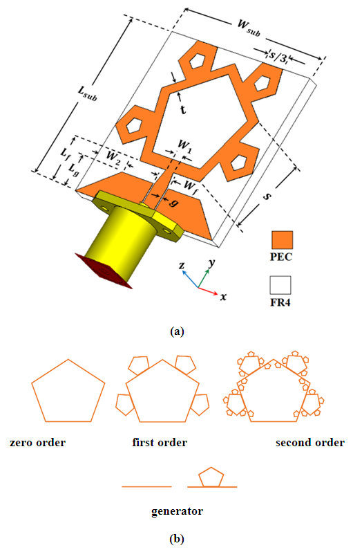 | Figure 1. (a) Configuration of the dual-band fractal antenna structure. (b) The recursive-generation procedure for a pentagonal fractal curve. Each perimeter segment of the curve is replaced with the generator. The pentagon structure, initiator or zero order, is shown along with the first two generating iterations |
2.2. Design Procedure
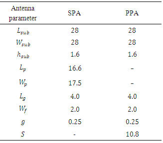
- Figures 2 and 3 illustrate the four systematic steps design procedure taken to develop the proposed dual-band antenna, namely:• Step-1 (SPA and PPA): As for designing dual-band antenna, two wide-band antennas based on CPW-fed are presented. One is a reference antenna, square patch antenna (SPA), and the other is a pentagonal patch antenna (PPA), see Figure 2. They are closely related to each other, and the size and parameter dimension values of them are equal. Initially, and knowing that the size of the antenna is determined approximately by the following formula:
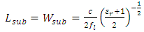 | (1) |
 and
and  , the length and width of antenna, respectively, are equal to half of the effective wavelength at
  , the lowest frequency of operation of antenna. c is the speed of light in free space and
  is the dielectric constant of substrate.Based on (1), we design the SPA by assuming that the thickness of the substrate
  ,
,  and
and  (the lowest frequency of 3.5-GHz WiMAX band) are given. Then, the SPA is square and has a size
  of
of  .
.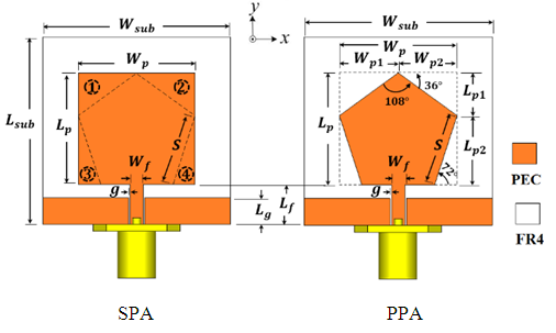 | Figure 2. Geometry of the SPA and PPA |
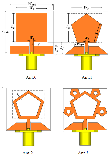 | Figure 3. Geometry of various antennas involved in the design evolution |
 and patch width
  of SPA is related to side length S of the PPA as:
 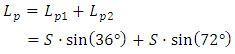 | (2a) |
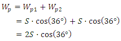 | (2b) |
 from simulation, the values of
  and
and  are 16.6 mm and 17.5 mm, respectively. As a result, return loss,
  curve in Figure 4 shows that SPA has
  and highest frequency of operation,
  . After SPA is successively designed to cover the 3.5-GHz WiMAX band, then PPA is generated from SPA by subtracting from it the four indicated triangles, 1, 2, 3, and 4, as shown in Figure 2. It is noted from Figure 4 that SPA and PPA
  curves are nearly similar in term of
  and they have different values of
  , 5.2 and 4.6 GHz, respectively.
|
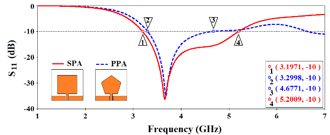 | Figure 4. CST simulated return loss,  curves of SPA and PPA curves of SPA and PPA |
 to
to  , i.e., 38% area reduction for each one compared with SPA and PPA counterparts. The comparison in terms of
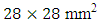
  plotsfor the intermediate antenna configurations, Ant.0 and Ant.1, besides Ant.2 and Ant.3, obtained from Steps 3 and 4 are illustrated in Figure 5, and the quantitative analysis are summarized in Table 2. It is noticed that for Ant.0 (Ant.1), two resonant modes of 3.9 and 5.3 GHz (3.9 and 6.5 GHz) and single operating band, 3.4-6.0 GHz (two operating bands, 3.5-4.6 GHz and 5.5-lager than7 GHz), are achieved. Due to the dual-band performance of Ant. 2, we need more design steps to achieve the desired operating bands, (3.3-3.7 GHz) WiMAX and (5.150-5.825 GHz) WLAN.
 | Figure 5. CST simulated return loss curves of various antennas |
 . Investigating
  plot in Figure 5, Ant. 2 operates in two bands, 3.30-3.98 GHz and 6.49-6.67 GHz, and has one resonant mode in each band, 3.59 and 6.57 GHz, respectively. It is still needed further design steps (iterative fractals) to bring these two bands of antenna to the required dual-band operation.
|
3. Results and Discussion
- The performance of the proposed antenna is simulated using commercially softwares, namely CST MWS and HFSS. The performance parameters deduced here are return loss, surface current distribution and far-field characteristics, gain, efficiency and radiation patterns.
3.1. Return Loss
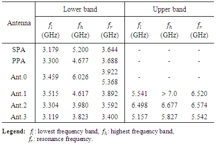
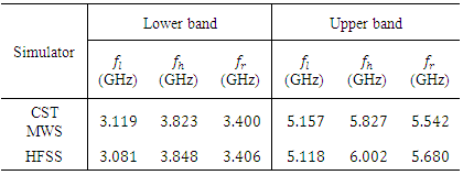
- Having successfully designed antenna by the procedure described in the previous section and the desired dual-band operation is satisfied, EM simulator based on HFSS is used to validate the result, return loss, obtained by CST MWS. Figure 6 illustrates the
 curve of the proposed antenna, Ant.3 or PRFPA, and its quantitative analysis in terms of
  and
and  is listed in Table 3. From Figure 6 and Table 3, a good agreement between two simulation results is observed. A slight difference between the two results can be attributed to different numerical techniques employed by the two simulators.
 | Figure 6. CST and HFSS simulated return loss of the proposed antenna |
|
3.2. Surface Current Distribution
- In order to investigate further the return loss performance of Ant.3, the surface current density distribution plots at its two bands’ resonant modes, 3.4 and 5.5 GHz, is depicted in Figure 7 using CST. It is observed that most current density is concentrated inside the pentagonal patch radiator, inside the feed line, at the connecting edge of radiating patch and feed line, and at near edges of ground plane and feed line. As shown in Figure 7, magnetic current density along the patch and the CPW-fed line is getting larger at lower resonant frequency, Figure 7(a), than that at larger resonant frequency, Figure 7(b).
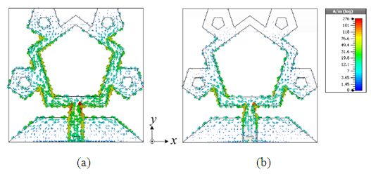 | Figure 7. CST simulated results of the surface current distributions for proposed antenna at (a) 3.4 GHz and (b) 5.5 GHz |
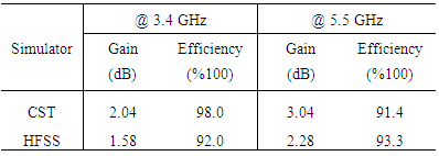
3.3. Far-field Antenna Performance
- Simulated peak-realized gain and efficiency against frequency for the two-resonance frequency bands is shown in Figure 8 and summarize of these results is illustrated in Table 4. Comparison between CST and HFSS results in terms of gain and efficiency as observed show reasonable agreement throughout the aforementioned bands. As Figure 8(a) shows, the CST (HFSS) has a maximum antenna gain of 2.05 dB (1.65 dB) in lower band and 2.44 dB (2.28 dB) in upper band whereas it has a minimum gain of 1.86 dB (1.4 dB) in lower band and 0.71 dB (1.11 dB) in upper band. Part (b) of Figure 8 shows that the efficiency remains above 98.0% (92.0%), 91.4% (93.3%), in the entire lower and upper band, respectively.
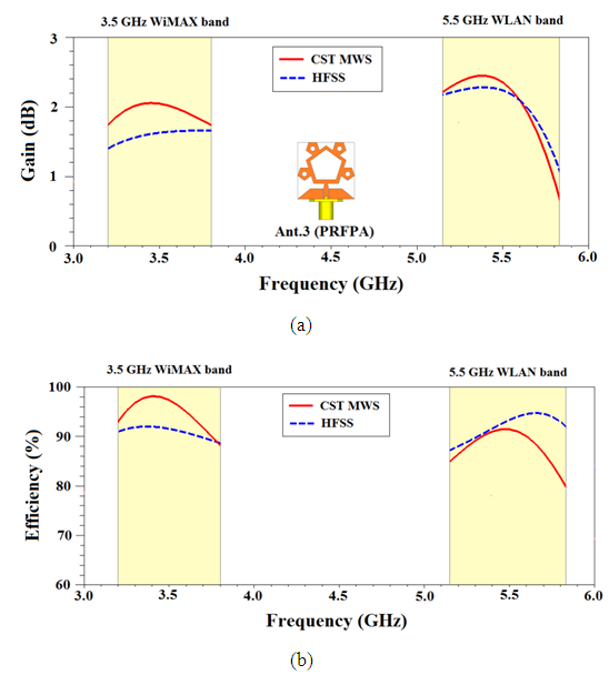 | Figure 8. CST and HFSS simulated results of (a) gain and (b) efficiency of the proposed antenna |
|
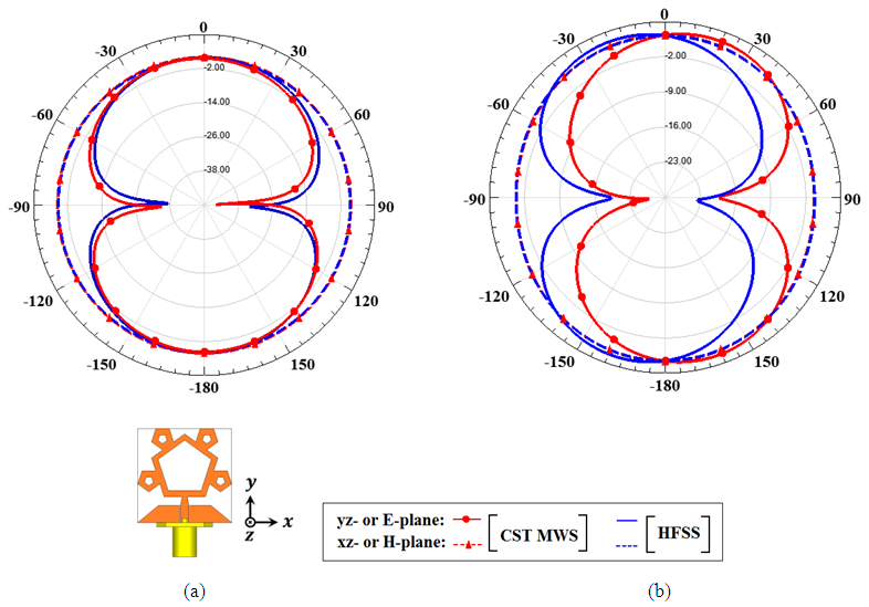 | Figure 9. CST MWS and HFSS simulated realized gain in E-plane (yz-plane) and H-plane (xz-plane) at (a) 3.4 and (b) 5.5 GHz |
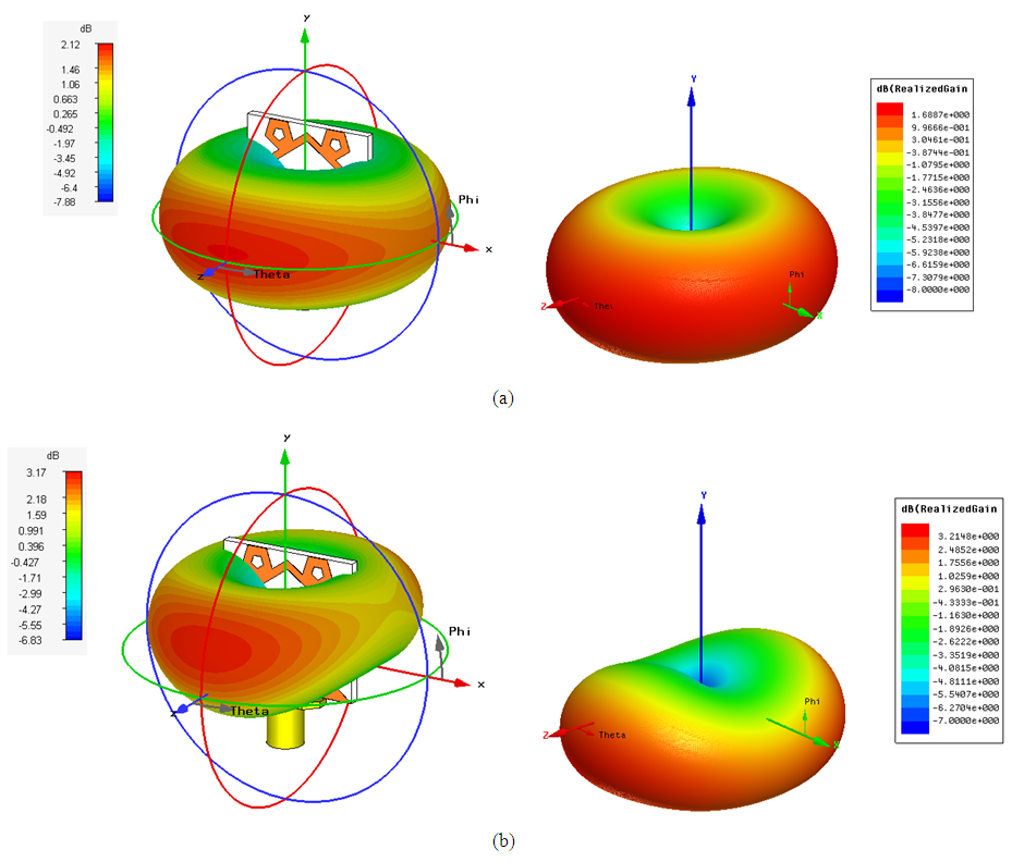 | Figure 10. CST MWS and HFSSsimulated3-Dfar-field radiation pattern at (a) 3.4 and (b) 5.5 GHz, [left: CST MWS, right: HFSS] |
 defined as
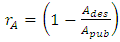 | (3) |
 and
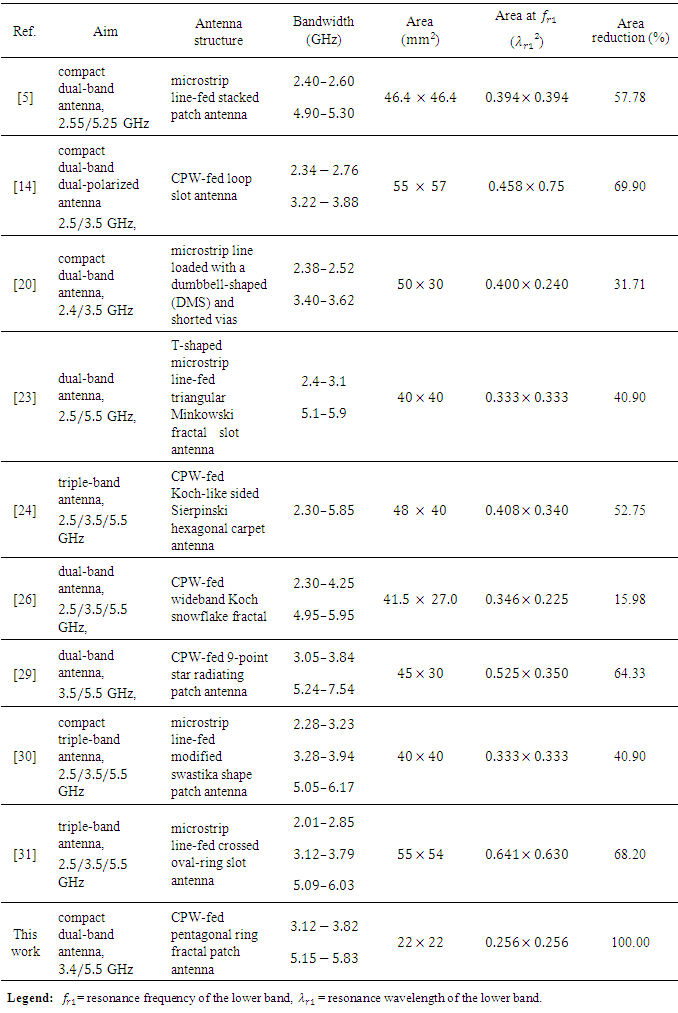
and  are the wavelength areas of the designed and published antenna, respectively. Table 5 lists the comparison of our proposed designed antenna with some other antennas that are already reported in literatures in terms of bandwidth, dimensions, and antenna area reduction. This comparison shows that the proposed antenna structure has the smallest area among antenna structures listed in Table 5. Moreover, developed antenna is suitable for dual-band applications.
|
4. Conclusions
- A dual-band pentagonal-ring fractal patch antenna (PRFPA) has been designed and numerically investigated. With the first-order fractal radiating structure, CPW feeding and tapered ground plane, the proposed antenna can be designed to operate at the 3.5-GHz WiMAX and 5.5-GHz WLAN bands. As required, a new design approach comprising of four systematic steps is introduced to achieve compact dual-band antenna, CPW-fed PRFPA, starting from wide-band reference antenna, CPW-fed square patch antenna (SPA). The proposed antenna designed is characterized by small size
 , 38% reduction in overall size in comparison with the reference antenna.The CST MWS is used for simulation and investigation of the designed antenna, and the results are confirmed by the aid of HFSS simulation tool. The results obtained from the two EM simulators are in close agreement validating the design concept. Owing to its simple structure, compact size, good radiation performance, and easy to fabricate and integrate with the application-specific circuit boards. This antenna is suitable for use in dual-band band communication systems for WiMAX and WLAN applications.