Surendra Loya1, Habibullakhan2
1Departmentof ECE, Usharama College of Engineering and Technology, Telaprolu, India
2Department of ECE, Koneru Lakshmaiah Educational Foundation, Vaddeswaram, India
Correspondence to: Surendra Loya, Departmentof ECE, Usharama College of Engineering and Technology, Telaprolu, India.
| Email: |  |
Copyright © 2016 Scientific & Academic Publishing. All Rights Reserved.
This work is licensed under the Creative Commons Attribution International License (CC BY).
http://creativecommons.org/licenses/by/4.0/

Abstract
Electromagnetic interference shielding means to use a shield (a shaped conducting material) to partially or completely envelop an electronic circuit. In the Aerospace industry, electromagnetic shielding plays an intricate part in the design process of any space vehicle. Electromagnetic fields from various devices may have tremendous effect on each other if proper shielding protection is not appropriately implemented. As industry standard, electromagnetic shielding is called shielding effectiveness. From Maxwell’s equations electromagnetic theory, the objectives of the shielding effectiveness calculations were to determine whether or not the selected tapes would conform to the 40 dB shielding effectiveness requirement as indicated in EMC specifications for electric field, magnetic field and planewaves from the system generated electromagnetic pulse, By using mathwork’s MATLAB the absorption loss, reflection loss, re-reflection correction factor, and the shielding effectiveness were computed for three different types of sheet metals.
Keywords:
Shielding, Shielding Effectiveness, Absorption loss, Refelection loss, Total Internal Reflection loss
Cite this paper: Surendra Loya, Habibullakhan, Analysis of Shielding Effectiveness in the Electric Field and Magnetic Field and Plane Wave for Infinite Sheet Metals, International Journal of Electromagnetics and Applications, Vol. 6 No. 2, 2016, pp. 31-41. doi: 10.5923/j.ijea.20160602.02.
1. Introduction
Electromagnetic radiation passes through the air and can interfere with the proper operation of various types of equipment. This is one of the basic reasons that EMI testing and EMC testing is performed. Circuit should be designed to both minimize the amount of electromagnetic radiation (interference) that it generates and also to tolerate electromagnetic interference from the environment by providing sufficient Electromagnetic Shielding. Electromagnetic shielding is the practice of reducing the electromagnetic field in a space by blocking the field with barriers made of conductive or magnetic materials. Shielding is typically applied to enclosures to isolate electrical devices from the 'outside world', and to cables to isolate wires from the environment through which the cable runs. Electromagnetic shielding that blocks radio frequency electromagnetic radiation is also known as RF shielding.A basic Electromagnetic Shield is to put the equipment in a metal box. Electromagnetic radiation (RF) cannot penetrate metal. A metal box is a great fix since there would be no Emissions from the circuit and no way the circuit would be affected by the outside electromagnetic environment. However, the usefulness of the circuit would be limited if we cannot get to it, electrically, visually, or mechanically. To access the circuit and give it usefulness we need to penetrate the electromagnetic shield (metal box). This is where the problems begin. RF can penetrate where there are apertures, penetrations and/or seams in the enclosure. The performance of the electromagnetic shielded enclosure depends on how the apertures, penetrations and seams are treated.
2. Shielding Effectiveness in the E-Field and H-Field and Plane Wave
Shielding effect is provided by a conductive barrier or enclosure that harmlessly reflects or transmits EMI into the ground.
2.1. Electric Field
Faraday cage principle states that the electric field inside a conductive, Spherical enclosure is nearly zero, the electric field generates both positive and negative charge switch in turn, generate a separate electric field. The thickness of the shield plays an insignificant role since electrons travel freely in conductive material.
2.2. Magnetic Field
In terms of magnetic field, Faraday’s principle does not apply, for magnetic charges do not exist. Nevertheless, magnetic material with high permeability (μ >> 1) and of ample thickness can create magnetic field attenuation by means of forming a low reluctance path that draws the material’s magnetic field. On the other hand, thin conductive materials with low permeability also have the capability to provide shielding effectiveness for magnetic field. The shield made of the material will form an alternating magnetic field that generates eddy current on the shield to provide shielding effectiveness. Eddy currents produce this alternating magnetic field of opposing orientation inside the shield. As a result, as frequency increase, shielding effectiveness will increase proportionally as well.
2.3. Plane Wave
Plane wave deems the magnetic field and electric field to be completely developed, in which case: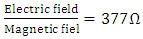 | (1) |
In order to achieve this condition, the distance to the radiation source needs to be far enough, or, in other words, in the Far-field region. Both the magnetic field and the electric field decrease in amplitude by 20 dB if the distance is increased ten times.In the Near-field region, however, shielding effectiveness must be observed separately for magnetic field and electric field. The ratio between the fields depends on the distance from the radiation source. Magnetic field controls the Near-field when the source has low impedance; conversely, the electric field takes over when the source has high impedance. Moreover, when the distance to the source is λ/2π, the wave impedance converges to 377Ώ and decrease linearly as the distance approach λ/2.
3. Shielding Tapes
Shielding tapes with a thickness of 0.35 x 10⁻³ inches (889μm) were placed at a distance of one meter from the electromagnetic source. The shielding tapes were assumed to be an infinite sheet, consequently eliminating edging effect. In order to coincide to requirements exclusively identified by the shielding equations stated in this report, some assumptions needed to be made. First, the selected tapes were assumed to be infinite sheets of metal without geometric dependencies. As previously stated, superalloy, aluminum, and mu-metal shielding tapes were selected for these calculations. The only criteria for this selection was each metal must have a permeability value drastically different from each other. By doing so, a range of possible shielding effectiveness values were obtainable. Second, for the lower frequencies (10 Hz to 10 KHz) of the magnetic field case, the calculated shielding range, which is roughly from –30 dB to 1800 dB, could quite possibly be impractical because geometric discrepancies exist in reality. Using these assumptions, the following quantities were calculated.
4. Shielding Effectiveness Calculations
Shielding effectiveness indicates the capability of a given metal material to operate as protection against external electromagnetic fields and as barrier preventing internal fields from damaging other devices. Its elements consist of simply the addition of the absorption loss, reflection loss, and re-reflection correction factor.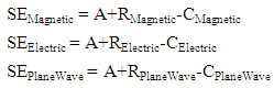 WhereSE = Shielding EffectivenessA = Absorption LossR = Reflection LossC = Re-Reflection Correction FactorUltimately, the complete shielding effectiveness of a metal sheet is the summation of three factors: absorption loss, reflection loss, and re-reflection correction factor. The calculation must be applied to all three fields: electric field, magnetic field, and plane wave. Nevertheless, one should keep in mind that these calculations are only a means to predict the shielding effectiveness of the metal, and should not be considered absolute.
4.1. Absorption Loss
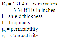
The absorption loss was computed first since all three fields have identical absorption losses. The absorption loss equation is a function of the EMI Shielding Characteristic of the metal used and the thickness of the tape: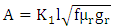 | (2) |
4.2. Reflection Loss
Reflection loss of a shield refers the reflection loss of a transmission line. It will be increases when the impedance of the electromagnetic field is much higher or lower than impedance of the shield. In this situation there is an imbalance between the two impedances, and power transfer from the field to the shield to put two in same position.Reflection loss equation for magnetic field is given by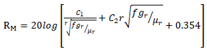 | (3) |
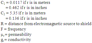 For electric field the equation is given by
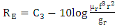 | (4) |
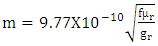
Where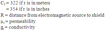 For plane wave equation is
 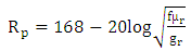 | (5) |
WhereF = frequencyµr = permeabilitygr = Conductivity
4.3. Re-Reflection Correction Factor
The re-reflection correction factor were required for proper shielding effectiveness results. The re-reflection correction factor was necessary only when absorption loss were less than 10dB.For magnetic field | (6) |
 | (7) |
R = distance from electromagnetic source to shieldF = frequencyµr = permeabilitygr = conductivityFor electric field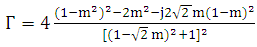 | (8) |
 | (9) |
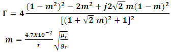
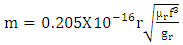
for the plane wave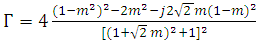 | (10) |
 | (11) |
5. Results
By using Matlab shielding effectiveness measured for three different shielding tapes and from the figures aluminum in green superalloy is indicated in blue and mumetal in red.From the above figure 2 aluminium shielding tape the least absorption loss, making more susceptible to reflected energy. For all three materials would require the use of re-reflection correction factor.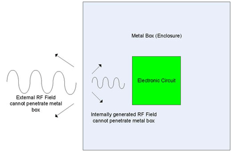 | Figure 1. EMI Mechanism |
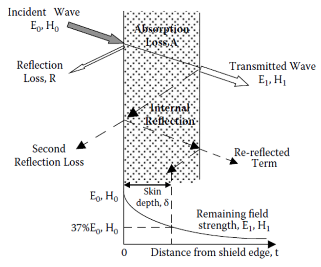 | Figure 2. Representation of shielding mechanism |
From the figures 3, 4, 5 reflection loss is more for aluminum in the magnetic field and for superalloy and Mumetal have similar values even their relative permeability values are far different.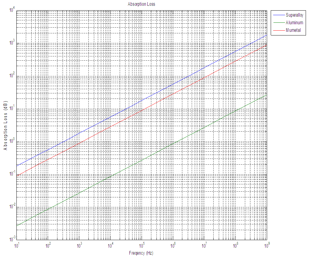 | Figure 3. Absorption Loss for Magnetic Field, Electric Field, and PlaneWave produced by Matlab |
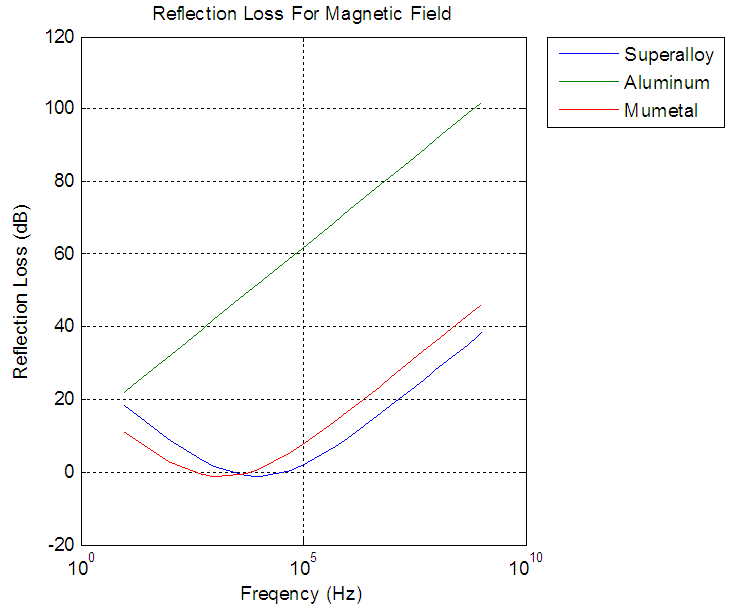 | Figure 4. Reflection loss for Magnetic field |
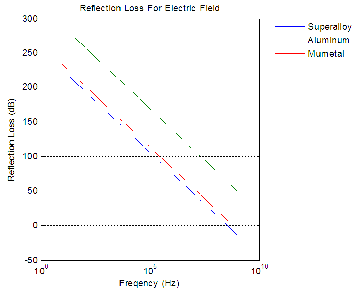 | Figure 5. Reflection loss for electric field |
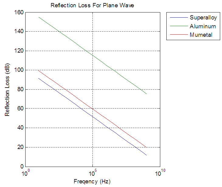 | Figure 6. Reflection loss for plane wave |
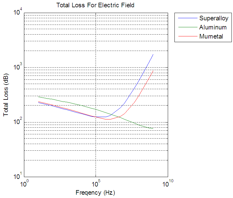 | Figure 7. Total loss for electric field |
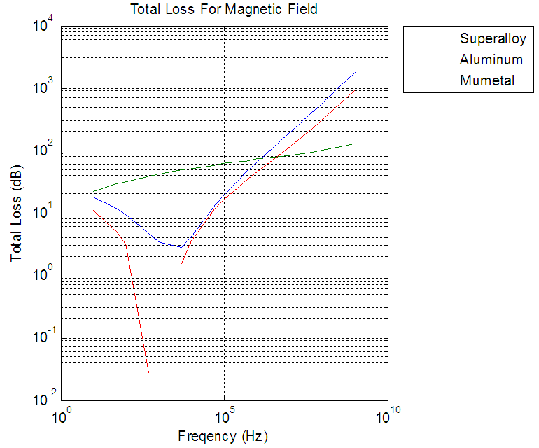 | Figure 8. Total loss for Magnetic field |
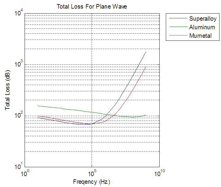 | Figure 9. Total loss for plane wave |
From all three fields aluminum had shortest range of shielding effectiveness 20dB to 150dB from frequencies of 10Hz to 1GHz and aluminum had grater shielding effectiveness because of greater reflection loss as opposed to superalloy and mumetal.The shielding effectiveness graphs produced when absorption losses are grater than 10dB. This is sum of the absorption loss and the reflection loss. The re-reflection correction factor is unnecessary because it will not greatly vary shielding effectiveness. 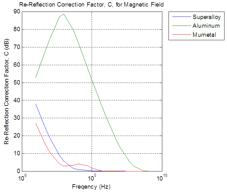 | Figure 10. Re-Reflection correction factor for magnetic field |
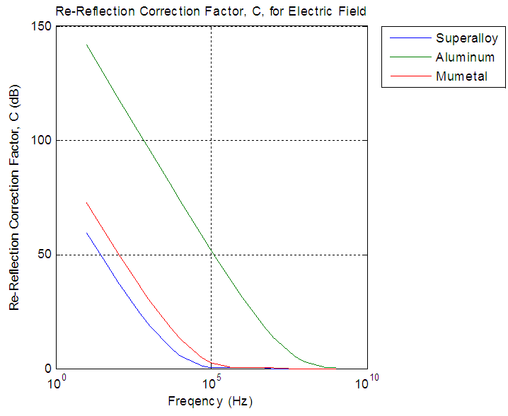 | Figure 11. Re-Reflection correction factor for Electric field |
From the figures the re-reflection correction factor was necessary only when absorption loss are less than 10dB, absorption for aluminum did not paas beyond 10dB approximately 100MHZ, and for superalloy and mumetal between 10KHZ and 100KHZ. The re-reflection correction factor approached to zero when frequency reaches 100MHZ for aluminum and100KHZ for superalloy and mumetal.From figures 12, 13, 14 in three fields aluminum was show least effective while superalloy was the most effective, and aluminium is providing adequate shielding of 40dB for frequencies greate rthan or equal to 1MHz in magnetic field, less than or equal to 1MHHz in electric field, and greater than or equal to 5KHz in plane wave. Superalloy was efficient in the electric field for the entire frequency spectrum and from 50Hz in the plane wave. Superalloy to be sufficient in the magnetic field proved to be 5KHz.Mumetal results similar to superalloy. 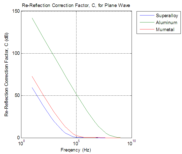 | Figure 12. Re-Reflection correction factor for plane wave |
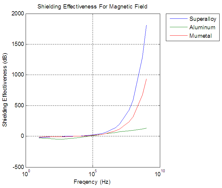 | Figure 13. Shielding effectiveness for Magnetic field |
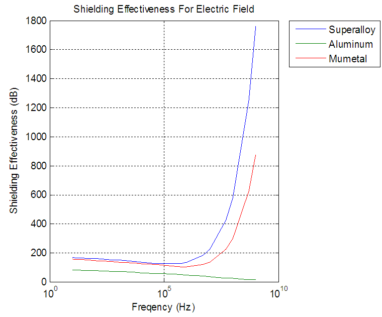 | Figure 14. Shielding effectiveness for Electric field |
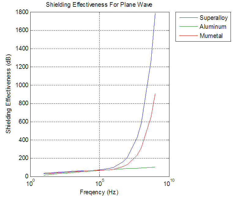 | Figure 15. Shielding Effectiveness for plane wave |
6. Conclusions
The shielding effectiveness of superalloy, aluminum, and mumetal shielding tapes satisfies the 40 dB shielding requirement as specified in the EMC Specifications of Military Standard Handbook 419A depending on the frequency and the SGEMP fields. Overall, the results confirmed that all three tapes were the most efficient in the electric field, which attested to being the easiest to protect against, even though aluminum was the weakest for frequencies greater than 1 MHz. Plane wave placed second in sufficiency among the fields for the selected metals. Lastly, magnetic field proved to be the most difficult to shield against for frequencies less than 1 MHz. Despite the fact that in reality, a shielding effectiveness of 200 dB is well beyond satisfactory, should there ever be a situation in which shielding is needed beyond that level, a shielding effectiveness up to 2,000 dB can be produced from these three metals, especially superalloy and mumetal.
ACKNOWLEDGMENTS
We thank the management of Usha Rama college of engineering and technology for all the support and encouragement rendered in this project. We also extend our sincere thanks to the Director and principal K Rajashekara Rao, Habibullah khan Dean Student Affairs of K L University for providing the required facilities to carry out this work.
References
| [1] | Engineering electromagnetic compatibility by V.prasad Kodali Second edition. |
| [2] | Principles of electromagnetic compatibility by Bernhard E.Keiser. |
| [3] | Paul, R. C., Introduction to Electromagnetic Compatibility, John Wiley Interscience, New York, 1992. |
| [4] | "IEEE Std. 299-2006", IEEE Standard Method for Measuring the Effectiveness of Electromagnetic Shielding of Enclosures, 1997. |
| [5] | J. R. Moser "Low-frequency low-impedance electromagnetic shielding", IEEE Trans. Electromagnetic Compatibility., vol. 30, no. 3, pp.202 -210 1988. |
| [6] | Hojo and Kamata Magnetic Shielding for Magnetic Cards, 1987. |
| [7] | Advanced materials and design for electromagnetic interference shielding by xingcuncolin tong CRC PRESS. |
| [8] | Schulz, R. B., V. C. Plantz, and D. R. Brush, \Shielding theory and practice," IEEE Trans. Electromagnetic Compatibility., Vol. 30, 187{201, August 1988. |

 Abstract
 Reference
 Full-Text PDF
 Full-text HTML