-
Paper Information
- Paper Submission
-
Journal Information
- About This Journal
- Editorial Board
- Current Issue
- Archive
- Author Guidelines
- Contact Us
International Journal of Electromagnetics and Applications
p-ISSN: 2168-5037 e-ISSN: 2168-5045
2016; 6(2): 23-30
doi:10.5923/j.ijea.20160602.01

Ultra Wideband Antenna with Reduced Radar Cross Section
 Abstract
 Reference
 Full-Text PDF
 Full-text HTML
Sunil S. Parit, Veeresh G. Kasabegoudar
P. G. Dept., MBES College of Engineering, Ambajogai, India
Correspondence to: Sunil S. Parit, P. G. Dept., MBES College of Engineering, Ambajogai, India.
| Email: |  |
Copyright © 2016 Scientific & Academic Publishing. All Rights Reserved.
This work is licensed under the Creative Commons Attribution International License (CC BY).
http://creativecommons.org/licenses/by/4.0/

Reduced radar cross section (RCS) is the key design parameter in stealth design of aircrafts and sea vessels. Therefore, such applications demand for the planar antennas capable of supporting reduced RCS. In this paper an octagon shaped planar UWB antenna is presented. The octagonal-shaped UWB antenna operates in the range of 3.6–16 GHz frequency range (115% impedance bandwidth). Proposed antenna exhibits more than 50% reduction in RCS than earlier reported similar geometries. The results presented indicate that the designed UWB antenna has lower RCS compared to the works reported earlier. Optimized results have been validated through fabricated prototype and found satisfactory agreement.
Keywords: Microstrip antenna, Ultra Wideband (UWB) Antenna, Reduced Radar Cross Section (RCS)
Cite this paper: Sunil S. Parit, Veeresh G. Kasabegoudar, Ultra Wideband Antenna with Reduced Radar Cross Section, International Journal of Electromagnetics and Applications, Vol. 6 No. 2, 2016, pp. 23-30. doi: 10.5923/j.ijea.20160602.01.
Article Outline
1. Introduction
- The growing significance of UWB communication, encouraged researchers to investigate on small antennas, since in many applications the antenna has to be small enough to be integrated into portable devices [1]. There are two types of antenna which meet these demands. The first one is derived from biconical antennas, but in planar configuration which includes bow-tie, diamond, circular and elliptical disc dipoles. The second one is originated from the development of monopole elements [2, 3]. A number of UWB monopole based upon different planar elements like circular, elliptical, polygon (square, pentagon, octagon) etc, have been demonstrated to provide UWB characteristics. However, most of these antennas are not suitable for applications which demand reduced radar cross section (RCS).It is well known fact that RCS determines how detectable an object is with the radar. There are various ways of reducing the RCS of target, like physical target shaping [4], applying Radar Absorbing Material (RAM) on surface of target, and using active elements on the surface [5]. The RAM material absorbs incident electromagnetic wave and reduces the RCS. For narrow bandwidth applications, a single coating of RAM is generally applied but for broad bandwidths different materials with multiple layers are coated [6]. Sometimes active elements are used which work on the principle of phase cancellation in the desired direction. In target shaping, the shape of the target is modified to change the direction of scattered energy from one angular region of interest to another unimportant region [7, 8]. In this paper, a UWB antenna is designed with a large circular cut section on the patch and ‘T’ section ground plane to have significant reduction in RCS as compared to [9] with overall performance similar to it. Although, the basic geometry is drawn from [9], the ground size is reduced by 49%. The detailed design and optimization of antenna geometry is discussed in Section 2. The geometry was optimized using Ansoft’s HFSS v.13.0 and the various results obtained are presented in the later part of this section. In Section 3, the validation results are presented and discussed. Details on the radar cross section and its reduction has been discussed in the latter half of this section. Finally, conclusion of the work presented is drawn in Section 4.
2. Design and Optimization
- In this work we have taken geometry of [9] for our further study and its typical dimensions are as listed in Table 1. More details regarding this work can be found in [9]. Basic geometry of the proposed antenna is shown in Figure 2. An FR4 substrate with a relative permittivity (εr) of 4.4, a loss tangent of 0.02, and a thickness of 0.8 mm has been used for design and optimization. Radiator patch is an octagonal-shaped with a circular slot of radius R = 5 mm whereas ground is T shaped with dimensions as shown in Figure 2 (b). The antenna is basically a monopole with defected ground structure (DGS). Ground size has been reduced significantly to have optimum RCS. The proposed antenna is excited with a tapered feed line of dimensions 6.0mm x 0.8 mm. The feed line is basically a microstrip line and is tapered for proper impedance matching.
|

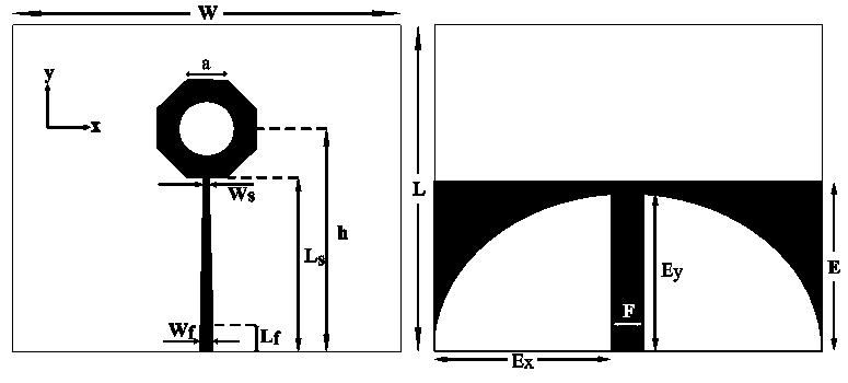 | Figure 1. Top and bottom view of reference octagonal-shaped UWB antenna [9] |
|

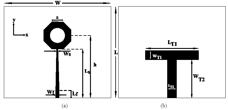 | Figure 2. Antenna geometry (a) Top view (b) Bottom view |
2.1. Geometry Optimization
- In this section a detailed parametric study has been conducted to optimize the antenna geometry for UWB operation. Parameters chosen for the purpose are various ground dimensions (LT1, WT1, LT2, and WT2), and radius (R) of the octagonal ring.
2.1.1. Effect of LT1
- In the beginning, the parameter LT1 was varied from 17.5mm to 70mm in steps of 17.5mm and observed its effect on the return loss characteristics. Only coarse variations are considered for the study as fine variations did not have significant changes on the geometry performance. Comparisons of these studies are presented in Figure 3. From Figure 3 it is observed that LT1=35mm offers the optimum performance. Reduction of LT1 below 17.5mm degrades the S11 performance and is mainly due to impedance mismatch between the ground and signal ports. Similarly further increase in LT1 beyond 70mm offers good S11 matching. However, these values are not considered as the primary objective of the work is to reduce effective RCS.
2.1.2. Effect of WT1
- In this study WT1 was varied from 5mm to 8mm (keeping all other parameters constant) in steps of 1mm. Effect of WT1 variation on antenna performance is presented in Figure 4. From the characteristics presented in Figure 4 it may be noticed that WT1=6mm offers the optimum results.
2.1.3. Effect of LT2
- Here, LT2 was varied and observed its effect on geometry performance. These values are changed from 5mm to 8mm and these effects are presented in Figure 5. From Figure 5 it may be noted that variation of this parameter has no significant changes on the S11 characteristics. Hence LT2=6mm was chosen (other than 6mm can also be chosen).
2.1.4. Effect of WT2
- In another effort WT2 (perpendicular stub of T section) was varied from 24.1mm to 27.1mm in steps of 1mm. Simulation results of this study is presented in Figure 6. It may be noted from Figure 6 that except for the case of WT2=24.1mm, all characteristics are nearly similar. Hence, WT2=25.1mm was chosen for the further study.
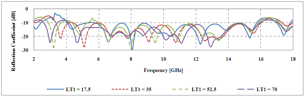 | Figure 3. Effect of the geometry parameter LT1 on the reflection coefficient (LT values are in mm) |
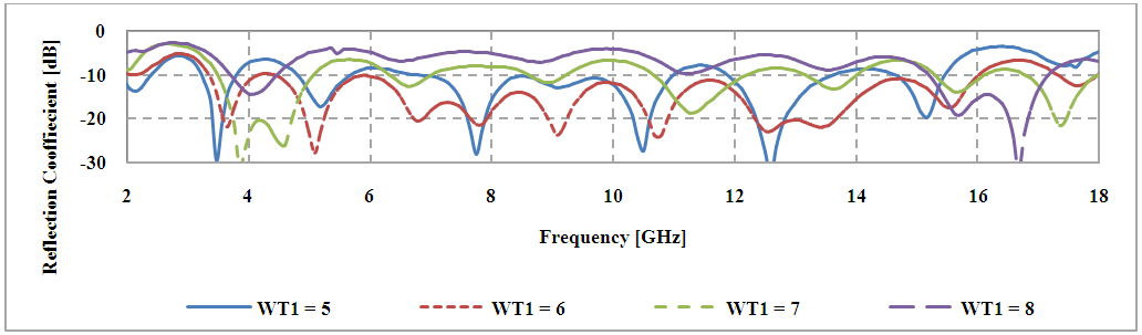 | Figure 4. Effect of the geometry parameter WT1on the reflection coefficient |
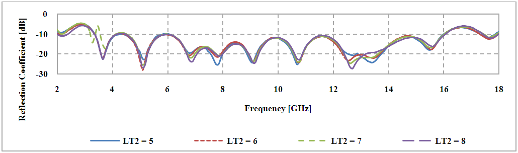 | Figure 5. Effect of the geometry parameter LT2 on the reflection coefficient |
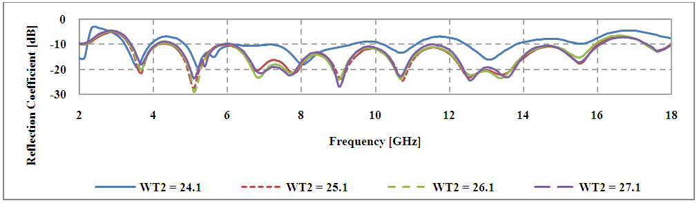 | Figure 6. Effect of the geometry parameter WT2 on the reflection coefficient |
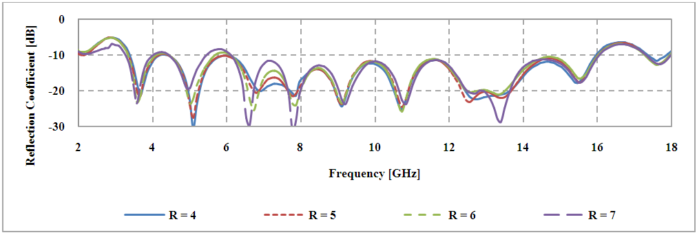 | Figure 7. Effect of slot radius (R) on the reflection coefficient |
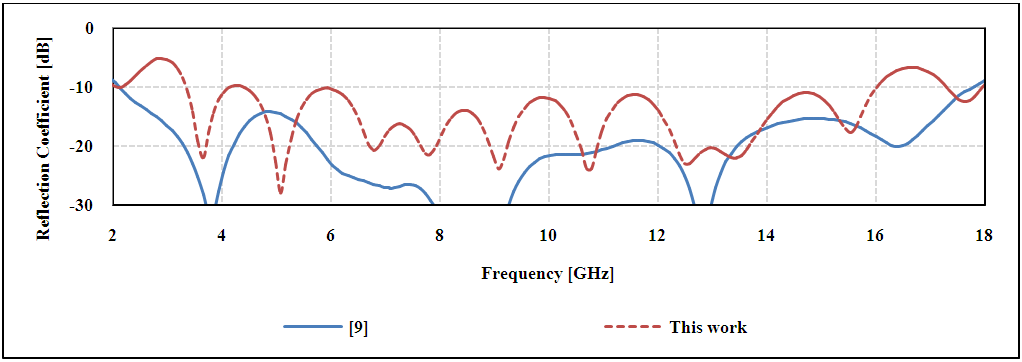 | Figure 8. Simulated results for reflection coefficient |
 | Figure 9. Impulse response comparisons |
 | Figure 10. Group delay vs. frequency plots |
2.1.5. Effect of Slot Radius (R)
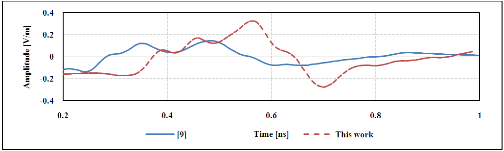
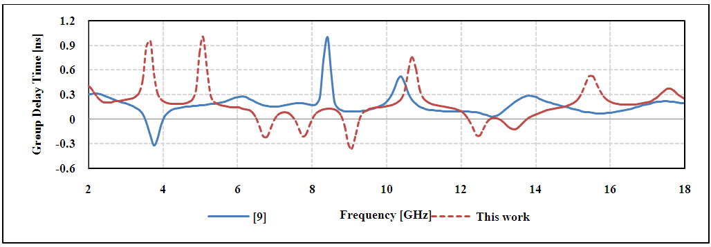
- Finally, the effect of circular slot on the reflection coefficient is investigated. Figure 7 shows the simulated results of the proposed antenna with various values of slot radius. Slot radius R is varied from 4mm to 7mm in steps of 1mm. As seen from Figure 7, the increase in R degrades S11 performance of antenna, especially in the 4GHz to 9GHz frequency range. From this study it is found the R=5 offers the optimum performance. With these parametric studies, the optimum antenna dimensions are obtained. Reflection coefficient characteristics comparisons of proposed antenna and [9] are shown in Figure 8. From Figure 8 it may be noted that performance of both geometries are nearly same. Although, S11 results of [9] appear to be better than that of present work, it may be noted that our effort is to reduce the radar cross section further keeping return loss bandwidth more or less similar to [9].To ensure a good reduction in RCS, metal area has been removed and investigated its effect on the time domain performance. Figure 9 shows the impulse responses of [9] and the proposed antennas. As seen from Figure 9, significant reduction of RCS has less effect on the time domain performance.Similarly, Figure 10 shows the simulated group delays for the reference [9] and proposed antennas. From the Figure 10 it may be noticed that after further reduction of RCS, the group delay response still remains nearly unchanged.
3. Experimental Validation of the Antenna Geometry
- In order to validate the optimized geometry, the antenna prototype was fabricated and tested (pl. ref. Figure 11). The substrate used is as suggested in Section 2 i.e., an FR4 with a relative permittivity (εr) of 4.4, a loss tangent of 0.02, and a thickness of 0.8 mm. VSWR vs. frequency comparison plots of the proposed antenna is shown in Figure 12. From the Figure 12 it may be noted that measured results agree with simulated results. More than 115% impedance bandwidth has been observed in the frequency range of 3.6GHz to 16GHz. Furthermore, it may also be noted that significant reduction in RCS has less effect on antenna performance (pl. ref. curve with legend [9]). The gain vs. frequency plots are presented in Figure 13. These plots indicate gain is positive across the band of operation (2 to 18 GHz). The radiation patterns are plotted at various frequencies across the band of operation and are depicted in Figure 14.
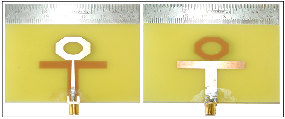 | Figure 11. Fabricated prototypes Top view (left) and bottom view (right) |
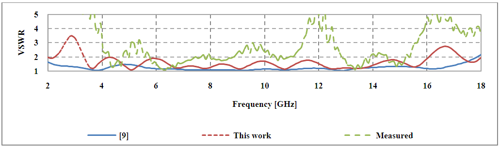 | Figure 12. VSWR vs. frequency plot comparison of the proposed antenna |
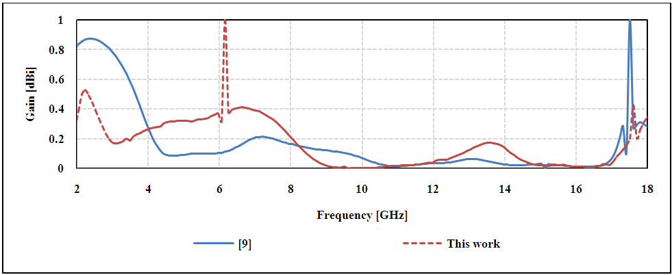 | Figure 13. Gain vs. frequency plots |
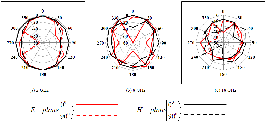 | Figure 14. Radiation patterns across the bands of operation |
3.1. RCS Reduction of Antenna
- The total RCS of an UWB antenna can be separated into two parts i.e., structural mode RCS and, antenna mode RCS. When an electromagnetic signal falls on an antenna surface, some part of the electromagnetic energy is scattered back to the space. This is called structural mode scattering. The remaining part of the energy is absorbed due to the antenna effect [13]. Some part of the absorbed energy is again scattered back into the space due to the impedance mismatches, called antenna mode scattering [16],
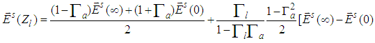 | (1) |
 | (2) |
 &
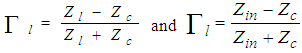
&  are the scattering field of the antenna terminated with open-circuit and short-circuit respectively and Γl is the reflection coefficient of load, and Γa is the reflection coefficient of antenna [17-19]. More details on the RCS can be found in [9].The RCS curves for x – polarization and y – polarization are simulated which indicate close to 50% reduction in RCS than the work reported in [9]. Figure 15 shows the comparisons of RCS of the proposed antenna and geometry reported in [9]. It may be noted that the reduction in RCS is significant especially in the low frequency range which is up to 25 dBsm [15].
 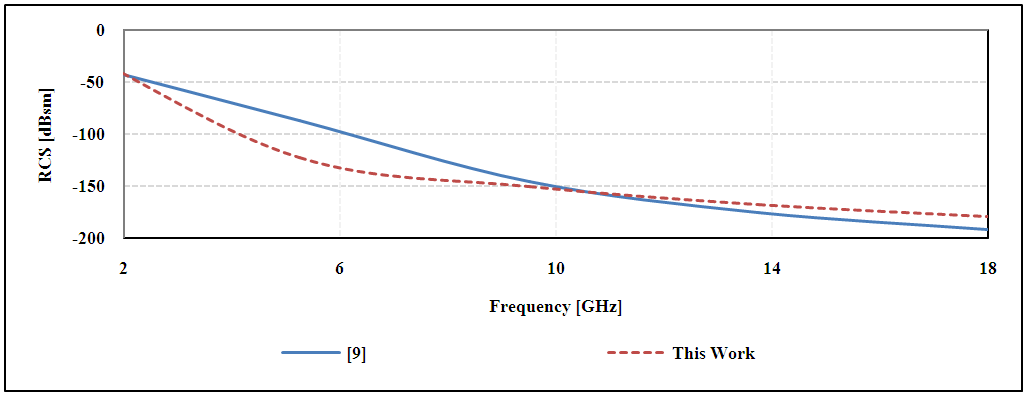 | Figure 15. Simulation results of monostatic RCS for x-polarized incident wave impinging from normal direction |
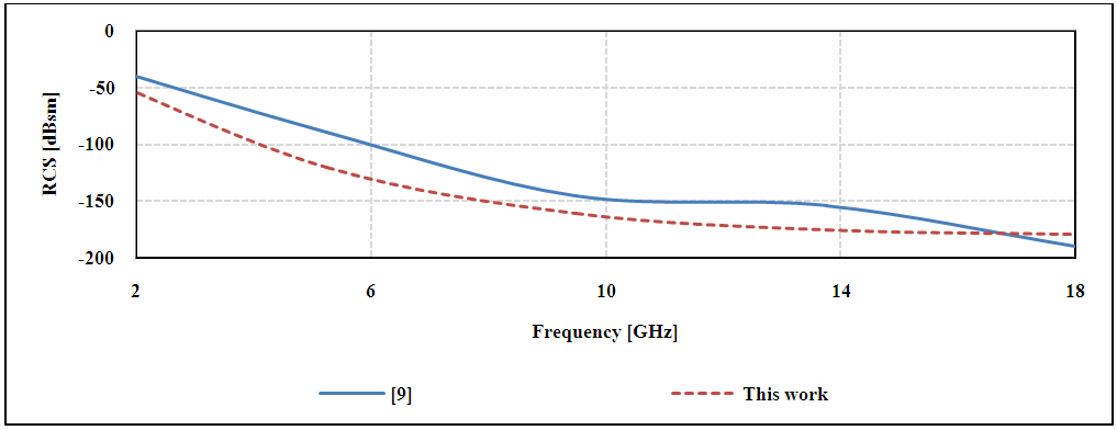 | Figure 16. Simulation results of monostatic RCS for y-polarized incident wave impinging from normal direction |
4. Conclusions
- An octagonal ultra wideband antenna with reduced RCS has been presented. The proposed antenna operates in the frequency range of 3.6GHz to 16GHz with impedance bandwidth of more than 115%. The antenna was optimized with improved RCS of nearly 50% (without affecting the overall performance) than the works reported earlier. The RCS reduction is achieved in a wide frequency band covering the wide operating band of the antenna by subtracting of metal areas which have the minimum current distributions on the surface of printed antenna. Measured results agreed with the simulated values. The proposed antenna is a good candidate where the application demands UWB operation with low RCS.