-
Paper Information
- Paper Submission
-
Journal Information
- About This Journal
- Editorial Board
- Current Issue
- Archive
- Author Guidelines
- Contact Us
International Journal of Electromagnetics and Applications
p-ISSN: 2168-5037 e-ISSN: 2168-5045
2016; 6(1): 13-21
doi:10.5923/j.ijea.20160601.03

Parametric Analysis and Modeling of Jerusalem cross Frequency Selective Surface
 Abstract
 Reference
 Full-Text PDF
 Full-text HTML
Payal Majumdar, Zhiya Zhao, Chunlin Ji, Ruopeng Liu
State Key Laboratory of Meta-RF Electromagnetic Modulation Technology, Kuang-Chi Institute of Advanced Technology, Shenzhen, China
Correspondence to: Payal Majumdar, State Key Laboratory of Meta-RF Electromagnetic Modulation Technology, Kuang-Chi Institute of Advanced Technology, Shenzhen, China.
| Email: |  |
Copyright © 2016 Scientific & Academic Publishing. All Rights Reserved.
This work is licensed under the Creative Commons Attribution International License (CC BY).
http://creativecommons.org/licenses/by/4.0/

In this study, we present the analysis and modeling of Jerusalem cross frequency selective surfaces adopting vector fitting procedure that ensures high accuracy with arbitrary terminal conditions. The simulations of microstructure are performed with full wave simulation tool CST Microwave Studio on single - layer and multilayer substrates with permittivity ranges from 2.2 - 4.3 in the frequency range 1 GHz – 30 GHz and substrate thickness ranges from 0.5 mm – 2 mm for different physical parameters. Then circuit models are extracted and developed using the vector fitting tool and implemented in a circuit simulator along with effect of polarization and angle of incidence. Then ADS SPICE generator is used for verifying circuit models developed using simulated results. The developed model is within 1% of average deviation against reference data.
Keywords: Equivalent Circuit Model, Frequency Selective Surface, Jerusalem Cross, Parametric Analysis, Vector Fitting technique
Cite this paper: Payal Majumdar, Zhiya Zhao, Chunlin Ji, Ruopeng Liu, Parametric Analysis and Modeling of Jerusalem cross Frequency Selective Surface, International Journal of Electromagnetics and Applications, Vol. 6 No. 1, 2016, pp. 13-21. doi: 10.5923/j.ijea.20160601.03.
Article Outline
1. Introduction
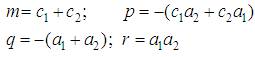
- A Frequency Selective Surface (FSS) is a periodic, planar assembly of generally metallic elements on a dielectric layer. It is built in conjunction with the EM waves in order to "tailor" an electromagnetic link in the free-space environment. Acting as a barrier for the waves propagating along the link, the FSS controls the flow of the EM energy. FSS has been an important topic because of their comprehensive applications, such as polarizers, filters, sub-reflectors, hybrid radomes, etc. [1, 2]. Nowadays hybrid -element based FSS structures are used to achieve significant bandwidth for airborne radome applications [3]. Several analytical or numerical electromagnetic methods (FEM, FDTD or MoM) have been used to analyze FSS. One of the simplest methods is the equivalent circuit model [3-12, 14]. The low computational effort required by the equivalent circuit method allows a faster design and analysis of FSS microstructures. Moreover, the approximate analysis, based on the parallel between real structure and a lumped - RLC - network counterpart is also useful for acquiring physical insights into the working principles of FSS [6].Unlike traditional microwave filters, the frequency response of FSS are not only functions of frequency, but also functions of incident angle and polarizations of EM waves. Consequently, it is necessary that an excellent FSS should provide stable performances for both various incidence angles and different polarizations within its operating frequencies. A new paradigm for designing modern multifunction structurally integrated array radars for low Radar Cross Section (RCS) platforms is the use of multilayer structures with integrated radomes and FSS’s. Thus, there is a growing demand for developing an accurate circuit model for FSS so that one can synthesize a desired frequency response by an optimization method in a reasonably short time using a circuit simulator [6]. In this paper, an equivalent circuit model for the analysis of Jerusalem cross (JC) has been presented, as shown in Fig.1. Being stable over wide range of parameters, the choice of JC-element allows the designer to tune its EM characteristics over the desired frequency range [3]. The simulations of microstructure are performed with full wave simulation tool CST Microwave Studio [19] on single -layer and multilayer substrates with permittivity ranges from 2.2 - 4.3 in the frequency range 1 GHz – 30 GHz and substrate thickness ranges from 0.5 mm – 2 mm for different physical parameters. The multilayer configuration of JC, as shown in Fig. 1(c), which consists of two FSS layers printed on both sides of a substrate are considered for study. The vector fitting (VF) technique [15-17] is used for determination of their poles and residues from simulated S-parameters [18]. Then the SPICE - compatible equivalent circuit model [13] of frequency-domain responses approximated by rational functions are developed. The transmission and reflection properties of JC FSS are evaluated through a simple and accurate circuit approach. The developed model is within 1% of average deviation against reference data.
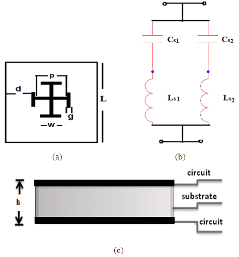 | Figure 1. (a) Layout of JC (b) its equivalent circuit and (c) Multilayer configuration with side view of the FSS |
2. Vector Fitting Methodology
- An efficient broadband modeling of transmission lines must also take into account the frequency - dependent behaviour of dielectrics. These effects materialize as a frequency domain variation in the resistance, inductance and capacitance matrices used in the formulation of the model. In practice, the frequency dependent responses are obtained via calculation or measurements as discrete functions of frequency [17].An attempt at formulating a general fitting methodology was introduced as VF method. Consider the rational function approximation [15]
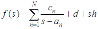 | (1) |
2.1. Real Poles
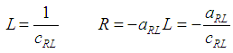
- The admittance of a series RL circuit represented in Fig. 2(a) to synthesize a function f(s) with a real pole is given by:
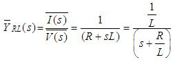 | (2) |
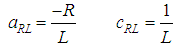 | (3) |
 | (4) |
2.2. Complex Pole Pair
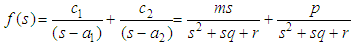
- Assume the pairs of complex and conjugate residues and poles be c1, c2, a1 and a2 respectively. The corresponding transfer function f(s) is [13]:
 | (5) |
 | (6) |
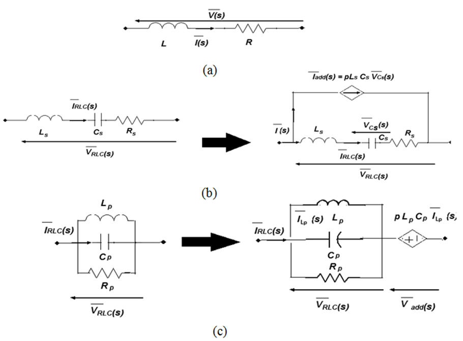 | Figure 2. (a) Equivalent RL circuit for real pole synthesis; (b) Equivalent series RLC circuit; and (c) Equivalent parallel RLC circuit for complex pole pair synthesis [14] |
2.2.1. Series RLC Circuit
- The improved transfer function f(s) of a series RLC circuit, to develop its equivalent circuit for complex pole pair synthesis [13], as shown in Fig.2(b), is written in terms of its residues and poles as
 | (7) |
 | (8) |
 | (9) |
 | (10) |
2.2.2. Parallel RLC Circuit
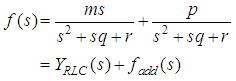
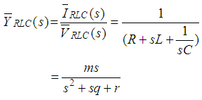
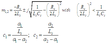
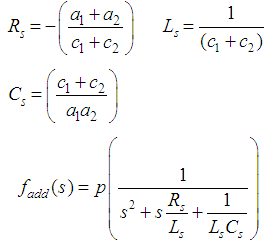
- The improved transfer function f(s) of a parallel RLC circuit, to develop its equivalent circuit for complex pole pair synthesis [13], as shown in Fig.2(c), is written in terms of its residues and poles as
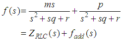 | (11) |
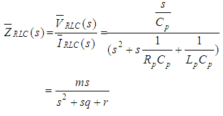 | (12) |
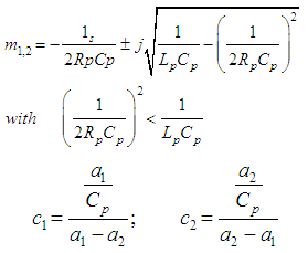 | (13) |
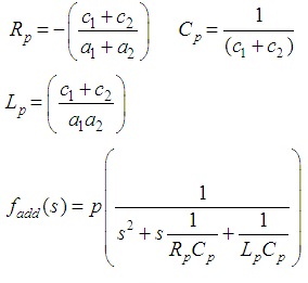 | (14) |
 Step 5) SPICE-compatible equivalent circuit synthesis [13].
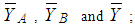
 | Figure 3. Equivalent П circuit |
 which have been synthesized in the equivalent circuit, as shown in Fig. 4, of FSS microstructure and simulated in a ADS SPICE [20] environment enabling both time and frequency analyses according to this approach [21-22].
 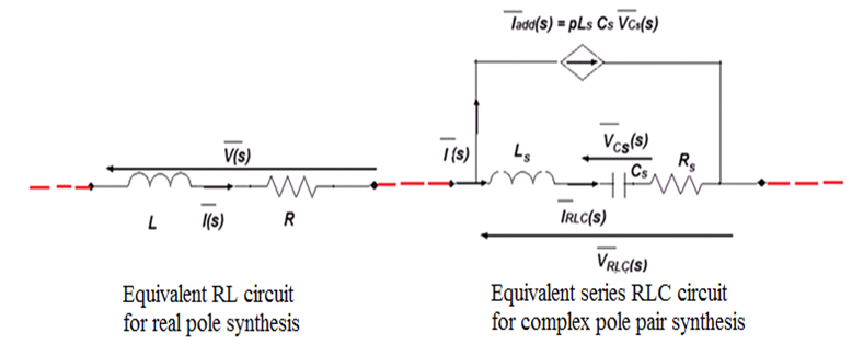 | Figure 4. Proposed equivalent circuit for JC FSS using VF |
3. Parametric Study of JC FSS
- The full-wave approach is necessary to establish the relationship between the physical parameters of the miniaturized unit cell and the lumped elements of the circuit model. So, JC FSS structure is studied and investigated on single-layer and multilayer substrates for different physical parameters using CST Microwave Studio [19]. The effects of oblique incidence and TE / TM polarization are also studied. TM - incidence occurs when the E-field is polarized parallel to the plane of incidence, i.e. θ = 0°, and TE - incidence when the E-field is perpendicular to the plane of incidence, i.e. Φ= 0°. The geometrical parameters of the designed JC FSS are: w = 3.5 mm, g = 0.5 mm, d = 1 mm, p = 7 mm and L = 10 mm on FR4 substrate with permittivity
 = 4.4, loss tangent tan δ = 0.025 and substrate thickness h = 1 mm.Fig. 5 shows the parametric study of JC FSS at normal, in terms of varying cell size, cross size and substrate thickness. Fig.5(a) and 5(b) show magnitude and phase of reflection and transmission characteristics respectively for different cell sizes. It can be observed that by decreasing cell size there is shift in resonance peak towards lower frequency for transmission characteristics. Fig.(5c) and (5d) show magnitude and phase of reflection and transmission characteristics respectively for different cross sizes. By increasing cross size there is shift in resonance towards lower frequency. It can be observed that by increasing cross size there is shift in resonance towards lower frequency. Similarly, Fig.(5e) and (5f) show magnitude and phase of reflection and transmission characteristics respectively for different substrate thicknesses. By increasing substrate thickness, there is shift in resonance towards lower frequency.
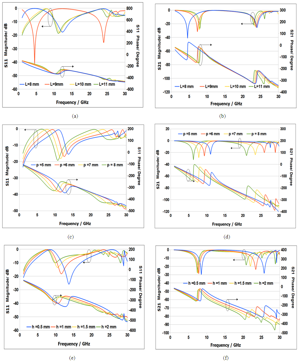 | Figure 5. Plane-wave reflection and transmission response at normal incidence for JC FSS |
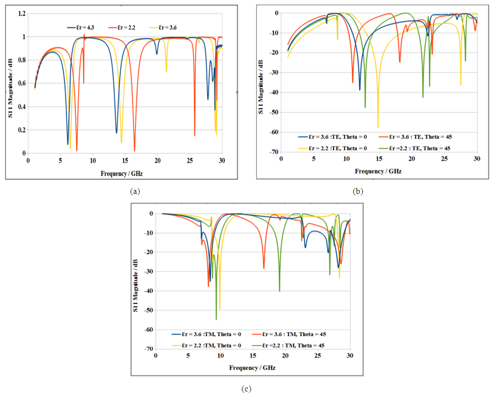
 = 4.4 and tanδ = 0.025; 2) Roger RT5880 with
  = 2.2 and tanδ = 0.008 and 3) Epoxy with
  = 3.6 and tanδ = 0.012, in the frequency range 1 GHz – 30 GHz and substrate thickness ranges from 0.5 mm – 2 mm, as shown in Fig.7. The results indicate that one can take advantage of low permittivity substrates to change or improve the frequency response of the designed filter. Fig.7(a) shows the effect of different substrates on reflection characteristics of multilayer JC FSS. Fig.7(b) and 7(c) show the effect of oblique incidence and TE/TM polarization on magnitude of reflection characteristics of multilayer JC FSS.
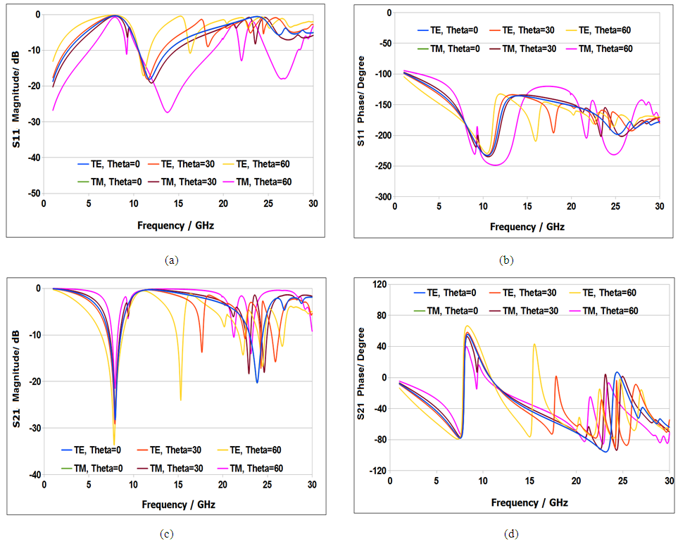 | Figure 6. Plane-wave reflection and transmission response at oblique incidence for JC FSS |
 | Figure 7. Plane-wave reflection and transmission response for multilayer JC FSS |
4. Model Verification and Results
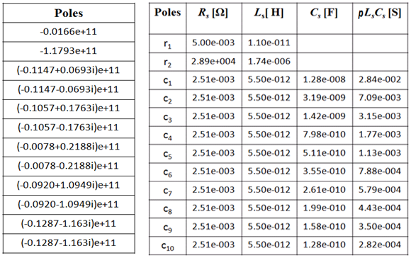
- In this section, the results of reflection and transmission characteristics of JC FSS obtained from the developed circuit model using VF tool, circuit model available from literature and CST simulations are compared against each other. The reflection and transmission characteristics of JC FSS have been fitted by using 12 poles [14, 17]. The fitting procedure has provided two real poles and five complex pairs, which can be synthesized in ADS SPICE generator using repeated units shown in Fig.4. Table 1 shows extracted poles and synthesized component values of JC FSS. Fig. 8 shows the plots of the magnitude and phase of reflection and transmission characteristics, those obtained by simulation, equivalent circuit from Fig.1(b) and equivalent circuit using VF technique.
|
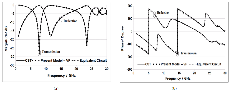 | Figure 8. JC FSS - (a) Magnitude and (b) Phase |
5. Conclusions
- The present work reports detailed investigation and study of JC FSS with resonant unit cells. The simulations are performed with CST Microwave Studio on single-layer and multilayer substrates for different physical parameters with permittivity ranges from 2.2 - 4.3 in the frequency range 1 GHz – 30 GHz and substrate thickness ranges from 0.5 mm – 2 mm. The VF tool is employed to extract equivalent circuits from S-parameters of JC FSS microstructure to use in circuit simulators to avoid time consuming 3D simulations. Then ADS SPICE generator is used for verifying circuit models developed using simulated results. All the models are within 1% of average deviation against reference data. The programming has been done in MATLAB. The method is useful for developing low-profile antenna applications based on FSS microstructures.
ACKNOWLEDGEMENTS
- This research work has been supported by grants from State Key Laboratory of Meta-RF Electromagnetic Modulation Technology (No. 2011DQ782011), Guangdong Province Engineering Laboratory for Millimeter Wave Meta-RF (No.1111), Shenzhen Key Laboratory of Data Science and Modeling (No. CXB201109210103A), Shenzhen Science and Technology Plan (No. JC201105201150A) and Shenzhen Science and Technology Plan (No. ZD201111080127A).