-
Paper Information
- Paper Submission
-
Journal Information
- About This Journal
- Editorial Board
- Current Issue
- Archive
- Author Guidelines
- Contact Us
International Journal of Electromagnetics and Applications
p-ISSN: 2168-5037 e-ISSN: 2168-5045
2015; 5(3): 108-111
doi:10.5923/j.ijea.20150503.02

A Dual-Band Bandstop Filter Having Open Stubs and Two Equivalent T-Shaped Lines
 Abstract
 Reference
 Full-Text PDF
 Full-text HTML
Shujun Yang
Department of Electrical Engineering and Computer Science, Alabama A&M University, Huntsville, USA
Correspondence to: Shujun Yang, Department of Electrical Engineering and Computer Science, Alabama A&M University, Huntsville, USA.
| Email: |  |
Copyright © 2015 Scientific & Academic Publishing. All Rights Reserved.
This work is licensed under the Creative Commons Attribution International License (CC BY).
http://creativecommons.org/licenses/by/4.0/

A compact dual-band microstrip bandstop filter (BSF) with two midband frequencies of 2.0 GHz and 3.0 GHz is presented. This filter is based on a conventional open-stub BSF with a midband frequency of 2.0 GHz. The series quarter-wavelength connecting line of the conventional BSF is replaced by two equivalent T-shaped lines to form the dual-band BSF. The impedances and electrical lengths in the equivalent T-shaped lines are found by equating the ABCD matrices of half of the original connecting line and one equivalent T-shaped line. Then the dimensions of the two equivalent T-shaped lines are calculated, and these two T-shaped lines generate a stopband around 3.0 GHz. The proposed BSF is simulated and fabricated. Simulation and measurement show this filter generates two stopbands around 2.0 GHz and 3.0 GHz.
Keywords: Bandstop filter, Open stub, Impedance, Equivalent T-shaped line
Cite this paper: Shujun Yang, A Dual-Band Bandstop Filter Having Open Stubs and Two Equivalent T-Shaped Lines, International Journal of Electromagnetics and Applications, Vol. 5 No. 3, 2015, pp. 108-111. doi: 10.5923/j.ijea.20150503.02.
Article Outline
1. Introduction
- Microstrip bandstop filters are being widely used in local oscillators, mixers, duplexers, switches, and other microwave subsystems. Various techniques have been developed to synthesize and design BSFs [1]. Dual-band bandstop filters are highly desired in some situations for their two separate stopbands. For example, dual-band BSFs have been used on RF/microwave amplifiers to reduce signal distortion [2, 3]. Various methods have been proposed to form dual-band BSFs. Dual stopbands can be obtained through frequency-variable transformation to the lowpass prototype [2] and cul-de-sac configuration [4], and the application of right/left-handed metamaterials [5], parallel open stubs at different lengths [6] and dual mode ring oscillators [7]. Conventionally, a dual-band BSF can be obtained by cascading two different BSFs. The side effect of this technique is an increase in circuit size. Size reduction of dual-band BSFs has been a hot research topic in recent years [8-16]. In this paper, a dual-band BSF is formed by replacing the series connecting line of a conventional open-stub BSF with two equivalent T-shaped lines. The impedances and electrical lengths in the equivalent T-shaped line can be found by equating the two ABCD matrices of the original transmission line and the equivalent T-shaped line. Then the dimensions of the two equivalent T-shaped lines are calculated. The proposed BSF is simulated on Sonnet Suite 14.52. Then the proposed filter is fabricated and measured. Simulation and measurement agree, showing this BSF generates two stopbands around 2.0 GHz and 3.0 GHz.
2. Open-Stub Bandstop Filter
- Figure 1(a) shows the configuration of a conventional open stub BSF. Usually the length of the two stubs and the separation between the two stubs are a quarter of the wavelength at the midband frequency [17, 18]. The substrate material is Rogers TMM10i with a relative dielectric constant of 9.9 and a loss tangent of 0.002. The thickness of the substrate is 1.27 mm. The back of the substrate is the ground plane. The dimensions of all the transmission lines are calculated directly on AppCAD software. AppCAD is a free RF/microwave design software provided by HP/Agilent. The width of the feed line and the width of the open stubs in this BSF are both 1.2 mm, which yields a characteristic impedance of 50 Ohm. The two open stubs are 14.61 mm long and the separation between the centers of the two open stubs is also 14.61 mm.
 | Figure 1(a). Layout of a conventional open-stub BSF |
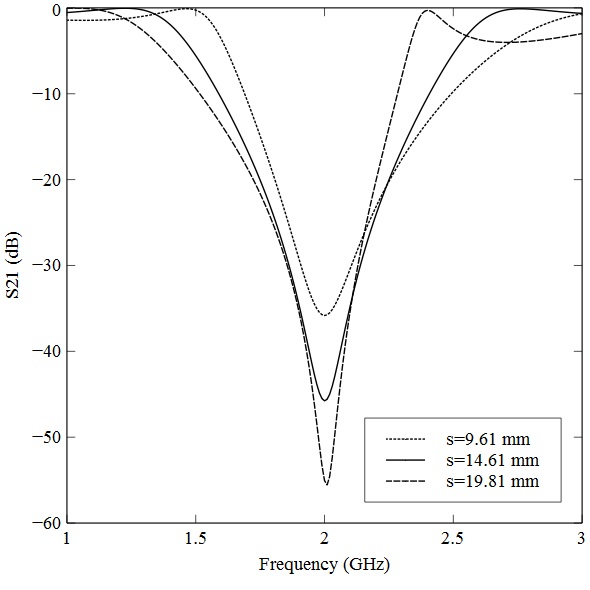 | Figure 1(b). Simulation results of the conventional BSF at selected stub separations |
3. Equivalent T-shaped Line
- Equivalent T-shaped Line was proposed by Tu and Chang to generate a stopband around second harmonic frequency on a conventional BSF and on an open-stub bandpass filter [18]. Figure 2(a) shows the schematics of an original transmission line and its equivalent T-shaped transmission line. Z1 and θ1 are the impedance and the electrical length of the original transmission line. Z2 and θ2 are the impedance and half of the electrical length of the horizontal line in the equivalent T-shaped line. Z3 and θ3 are the impedance and the electrical length of the vertical line in the equivalent T-shaped line.The impedances and electrical lengths in the equivalent T-shaped line can be found by equating the two ABCD matrices of the original transmission line and the equivalent T-shaped line [18, 19]. Ning, Luo, and Bu derived two general formulae for the equivalent T-shaped line as [19]
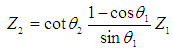 | (1) |
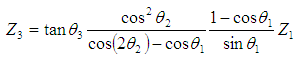 | (2) |
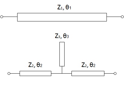 | Figure 2(a). An original transmission line and its equivalent T-shaped line |
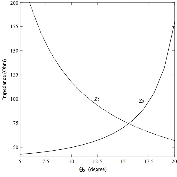 | Figure 2(b). Z2 and Z3 versus θ2 with 60 degrees θ3 |
4. Proposed Bandstop Filter
- The proposed BSF is realized by replacing the connecting line between the two open stubs of the conventional BSF (described earlier) with two equivalent T-shaped lines. The two equivalent T-shaped lines yield a second stopband. For half of the connecting line, Z1 should be 50 Ohms, and the electrical length θ1 should be 45 degrees. The vertical electrical length θ3 was chosen as 60 degrees for the second stopband to be around 3.0 GHz. Then Z2 and Z3 are calculated as functions of θ2 (Figure 2(b)). Next, the equivalent horizontal electrical length θ2 was chosen as 15 degrees. Then Z2 and Z3 can be calculated as 77.29 and 70.20 Ohms. Figure 3(a) is the layout of the equivalent double T-shaped lines. All dimensions are calculated directly on AppCAD software. The vertical Z3 line is 0.53 mm wide and 10.06 mm long. The Z2 connecting line between the two Z3 lines is 0.40 mm wide and 5.07 mm long. The double T-shaped lines structure is simulated on Sonnet Suite 14.52. Simulation results are shown in Figure 3 (b). A stopband is generated around 3.0 GHz and the deepest rejection is more than -25 dB.
 | Figure 3(a). Layout of the equivalent double T-shaped lines |
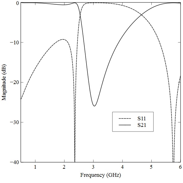 | Figure 3(b). Simulation results of the double T-shaped lines |
 | Figure 4(a). Layout of the proposed BSF |
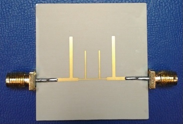 | Figure 4(b). Picture of the fabricated filter |
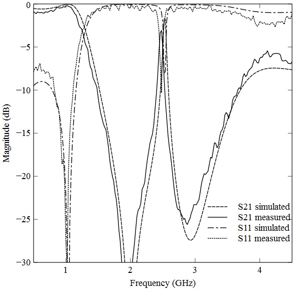 | Figure 4(c). Simulation and measurement results of the proposed dual-band BSF |
5. Conclusions
- The series connecting line of a conventional open-stub BSF with a midband frequency of 2.0 GHz is replaced by two equivalent T-shaped lines to form a dual-band BSF. The impedances and the electrical lengths in the equivalent T-shaped lines are found by calculations on ABCD matrix. Then the dimensions of the T-shaped lines are calculated on AppCAD software. Simulation of the double T-shaped lines shows the formation of a stopband around 3.0 GHz. The proposed BSF is simulated and fabricated. Simulated and measured results agree, showing two stopbands are generated around 2.0 GHz and 3.0 GHz.
ACKNOWLEDGEMENTS
- The author would like to thank Dr. Montgomery, Dr. Scott, Dr. Heidary and Mr. Pryor for their helps.