Charles U. Ndujiuba , Adebiyi A. Adelakun , Oboyerulu E. Agboje
Electrical & Information Engineering, Covenant University, Ota, Nigeria
Correspondence to: Charles U. Ndujiuba , Electrical & Information Engineering, Covenant University, Ota, Nigeria.
| Email: |  |
Copyright © 2015 Scientific & Academic Publishing. All Rights Reserved.
Abstract
The performance of microstrip patch antenna system depends on the characteristics of the antenna element and the substrate as well as the feed configuration employed. Here the principal characteristics of interest are the antenna input impedance, mutual coupling, bandwidth, radiation pattern and return loss. In large multilayer array networks the computational time and effort required for the analysis of these characteristics become important with size and complexity of the geometries of the antenna systems. In this paper, we combine the simplicity of the Transmission Line method and the accuracy of the Integral Equation method to obtain a Hybrid method. First we develop a simplified equivalent circuit model of a single aperture-coupled patch antenna using the Transmission Line method. Then we develop a simplified model that can be used to efficiently analyse the characteristics of an aperture-coupled patch antenna array, using the Integral Equation Method. For its application to the problems of antenna phased arrays, a modification of the model will be obtained, taking into account the effects of coupling between the antenna elements and the resulting reflection coefficient which is related to scan blindness and surface waves. The major advantage of the proposed model is the reduction of the large computing time involved in the existing rigorous method which is based on the combined field Integral Equations and the Method of Moments (MoM).
Keywords:
LTE system, Antenna arrays, Mutual coupling, Input impedance, Radiation pattern, Method of Moment
Cite this paper: Charles U. Ndujiuba , Adebiyi A. Adelakun , Oboyerulu E. Agboje , Hybrid Method of Analysis for Aperture-Coupled Patch Antenna Array for MIMO Systems, International Journal of Electromagnetics and Applications, Vol. 5 No. 2, 2015, pp. 90-97. doi: 10.5923/j.ijea.20150502.03.
1. Introduction
The most preferred antennas on any mobile unit for a MIMO system are microstrip or patch antennas, due to their low cost and ease of fabrication. These benefits justify our interest in this subject.The main drawback of these antennas is low bandwidth and there are various techniques proposed for improving the bandwidth.The bandwidth of the microstrip patch antenna can be improved by increasing the thickness of substrate or by decreasing its electric permittivity value.The practical design or analysis of an aperture-coupled microstrip patch antenna, or an array of such antennas, is done by means of software packages. Existing programs developed from the methods of analysis presently in use give rise to a very slow numerical convergence of solutions, especially those of the rigorous methods. Although these rigorous and complicated methods yield more accurate results than the simplified methods, they require a lot of computational and real-time effort even on powerful computer systems. Sometimes, less accurate results suffice, and can be obtained much faster with the help of simpler methods which adequately describe the characteristics of the antenna system, by simple design equations.In addition to compatibility with integrated circuit technology, microstrip antenna systems offer other benefits such as thin profile, light weight, low cost and conformability to a shaped surface. Its main disadvantage is inherent narrow bandwidth arising from the fact that the region under the patch is basically a resonant cavity with a high quality factor.The basic geometry of a single aperture-coupled microstrip patch antenna is shown in Figure 1 [1, 2]. It consists of two substrates bonded together and separated by a ground plane between them. On the top substrate is printed the radiating patch (antenna) while a microstrip feedline is printed on the bottom substrate, which is electromagnetically coupled to the patch by means of a small resonant aperture in the ground plane.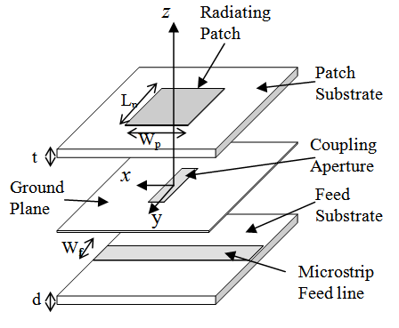 | Figure 1. Single Aperture-coupled Antenna |
Several advantages are obtained by the use of such two-sided configuration. These include isolation of the feed network from the radiating aperture, which eliminates the spurious feed network radiation that can degrade polarization and sidelobe levels. Also, the two-sided configuration provides two distinct microstrip line media so that the antenna substrate can be chosen to optimize the performance of the radiating patches (e.g. low permittivity to improve radiation and increase bandwidth), and the feed substrate can be chosen independently to optimize feed performance.Feed structures for microstrip antennas take various forms. The main ones are the coaxial probe, the microstripline, and the aperture coupling methods.The choice of the feed arrangement may depend on the application of the antenna system. For example, at millimeter wave frequencies the use of the aperture coupling obviates problems of large probe self-reactances associated with probe feeds. The connector effects, at the junction of the probe and the antenna element, give rise to fundamental limits to antenna performance due to radiation from the discontinuity at the junction.
2. Methods of Analysis
A number of methods are presently in use to analyse the characteristics of patch antennas. They are broadly classified under two categories:i. Simplified Method● Transmission-line model● The Cavity model● Method of segmentationii. Exact or Rigorous Method● The Integral Equation methodIn view of the respective benefits and setbacks of these methods, it has been established that while the integral Equation method offers rigorous and thorough approach with accurate results, it requires a large amount of computational time [3]. On the other hand, the Cavity and transmission-Line methods require less time but give approximate results. Among these methods only the Integral Equation method is most suitable for the Aperture-coupled system, in view of the complexity in its construction.
2.1. Transmission-Line Analysis of the Aperture-Coupled Patch Antenna
The single aperture-coupled patch of Figure 2 is analysed in this work by a transmission-line approach, in order to have a fast and efficient procedure for computing the parameters of the radiating patch.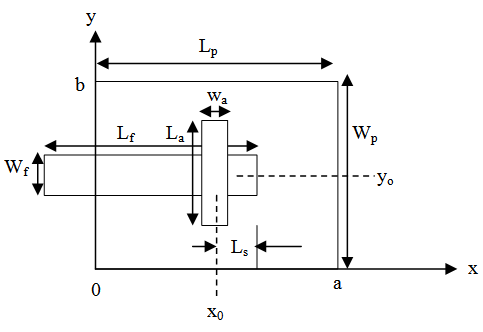 | Figure 2. Geometry layout of Aperture-coupled Patch Antenna |
The antenna system is separated into two regions as shown in Figure 3(a).There are two symmetrical regions, represented as regions I, in which the microstrip line is separated from the antenna patch by the ground plane. This is the uncoupled region.Region II describes the medium of electromagnetic coupling between the feedline and the antenna patch. This region can be given a physical interpretation using an impedance model as in Figure 3(b) [4].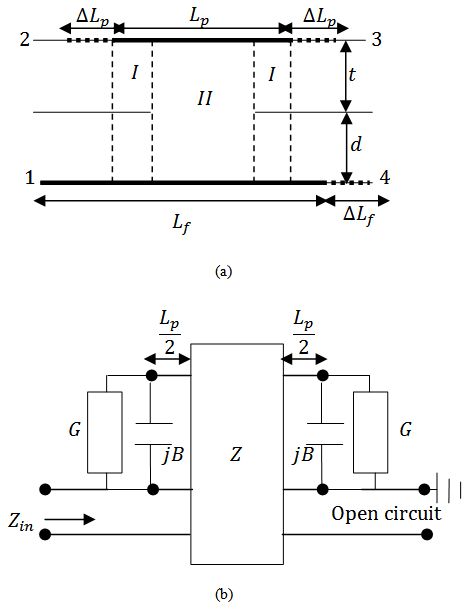 | Figure 3. Patch antenna system for analysis: (a) Side view, (b) Transmission line model of the patch antenna |
Different circuit arrangements can be used to interpret this model. Figure 4 represents one possible arrangement.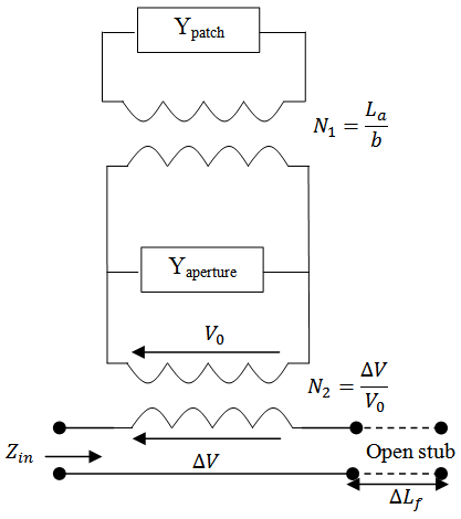 | Figure 4. Equivalent circuit of Aperture-couple patch antenna |
The resonant length of the rectangular patch antenna determines the resonant frequency and is λ/2 in its fundamental mode. In its fundamental mode, the length and width are calculated by the formulas [5] | (1) |
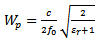 | (2) |
As shown in Figure 3(a), the fringing effects of the discontinuities at the open ends 2, 3 and 4, are represented by a hypothetical electrical extensions  and
and  The effective lengths of the patch and feedline, respectively, become
 | (3) |
 | (4) |
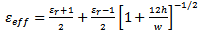
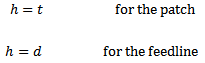
where [2]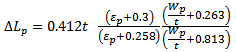 | (5) |
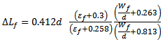 | (6) |
and  and
and  are the effective dielectric constants of the patch substrate and the feedline substrate, respectively.Since the patch radiates electromagnetic energy mainly through the two narrow slots along the two open ends of the patch,
  is used to express the radiation conductances at these ends. This is shown in Figure 3(b). Using the modified Sobol’s formular [6], the conductances are calculated as
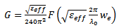 | (7) |
where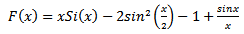 | (8) |
 | (9) |
 | (10) |
and | (11) |
 The effective width,
  takes into account the fringing effects while
  and
and  are the effective dielectric constant and the characteristic impedance respectively, of the patch.When
  equation (7) may be simplified as
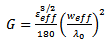 | (12) |
The value of the susceptance is calculated from [7] | (13) |
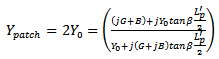
where  is given in equation (5), while
  is the free space velocity.From Figure 5,
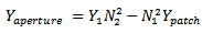 | (14) |
 | (15) |
 | (16) |
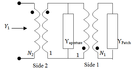 | Figure 5. Coupling between feedline and aperture (side 2), and coupling between aperture and radiating patch (side 1) |
Taking into account the open-circuited stub in Figure 3(a), the total input impedance is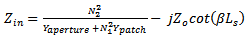 | (17) |
where  is the characteristic impedance and
  is the effective propagation constant on the microstrip feedline of open-circuited length
  which accounts for
  According to [8], the transformation ratio
  is equal to the fraction of current flowing through the aperture over the total intensity:
 | (18) |
and  | (19) |
 | (20) |
The knowledge of  enables the aperture admittance to be determined using equation (17).
2.2. The Integral Equation Method
Among its features, the Integral Equation model is able to handle patches of arbitrary shapes, and also has no limitations in frequency and substrate thickness. The model also takes into account mutual coupling between adjacent elements and can predict surface waves as well as dielectric and conductor losses.The object of the analysis is to determine the surface current  on the patch conductor (antenna element) and then deduce all antenna electric characteristics.For perfectly conducting bodies
 | (21) |
wheredenotes the surface of the conductor on which current  is located.
  denotes the volume containing the feed source
 denotes the feed current
 denotes the field generated by surface current
  computed via the expression:
 | (22) |
where is a dyadic Green’s functionIt takes into account the dielectric substrate and, in general, the boundary conditions at the various interfaces.To solve the above integral equation we implement the Method of Moments (MoM) for which
  is decomposed into basis function
  [9]:
[9]: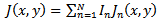 | (23) |
 denotes the coefficient of the basis functions, which are the unknowns. The shape and the number of N of the basis functions
  must be carefully selected such that they reflect the assumed distribution of current
  In spectral domain we obtain the system:
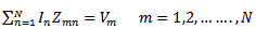 | (24) |
where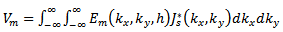 | (25) |
where is the substrate thickness,
 is the electric field generated by a test function chosen on the upper conductor,
 is the conjugate of Fourier transform of feed current density
  A schematic of an antenna and feedline is shown in Figure 6 (a) and (b), with impressed and induced currents indicated.
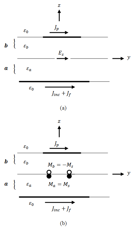 | Figure 6. Aperture-coupled microstrip antenna with (a) surface electric currents (b) with surface electric and magnetic currents |
The known incident current distribution on the field line is denoted by Jinc, the scattered feedline current by Jf, and the patch current by Jp. By invoking the equivalence principle the aperture can be closed off and replaced by magnetic surface currents Ms just above and below the ground plane. To ensure the continuity of the tangential electric field through the aperture, the magnetic current above the ground plane is made equal to the negative of that below.Denoting the space below the ground plane as region a and the space above the ground plane as region b, the total electric and magnetic fields in each region can be written as a summation of fields due to the various currents as follows [10-13]: | (26) |
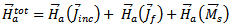 | (27) |
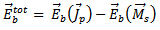 | (28) |
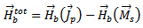 | (29) |
Each field on the right side of the equations is due to the specified current, radiating in the presence of a dielectric slab and ground plane with the aperture shorted. They can therefore be represented by their integral equations, for example | (30) |
where  and order Green’s functions needed for the analysis are obtained by using Spectral Domain Methods.
 | (31) |
where  is the Fourier transform of the electric field
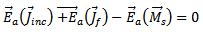
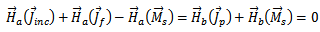
  Three coupled integral equations are obtained for the three unknown currents, Jf, Jp, and Ms, by enforcing the boundary conditions:

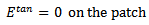 The total electric field in the patch region is the sum of electric field generated by electric patch current and electric field generated by magnetic aperture current which can be written on the patch as:
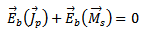 | (32) |

 | (33) |

 | (34) |
A Moment Method solution of these equations is formulated by choosing expansion functions for the unknowns. For the patch current,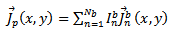 | (35) |
Then the electric and magnetic field equations can be used to enforce the boundary conditions. This results in the matrix equation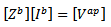 | (36) |
where  is the column vector of unknown patch expansion mode coefficients,
  is the moment method impedance matrix of the patch, and
  is the voltage vector due to the excitation of the magnetic currents in the aperture.
2.3. Calculation of the Radiation Field
The tangential electrical field in the slot apertures can be written as: | (37) |
As a result of the presence of image on the slot we find that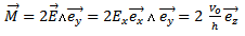 | (38) |
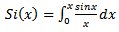
The uniform distribution of the tangential electric field,  on the slots permits us to calculate the far-field,
  from each of the slots.
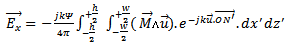 | (39) |
where w = length of the sloth = width of the slot and
and N’ describes the surface of the slot with
 with the magnetic current source
 | (40) |
we obtain | (41) |
with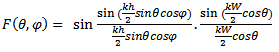 | (42) |


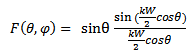 | (43) |
The total field radiated by two slots is obtained by:(a) Redefining the origin at the center of the antenna,(b) Applying the theory of translation to the fields radiated by each of the slots, Es1 and Es2.Thus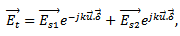 | (44) |

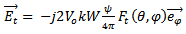 | (45) |
where,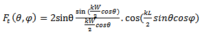 | (46) |
3. Analysis of Antenna Phased-Array
So far, the methods have been developed for a single patch antenna. They are also applicable to the array systems, but requiring some modifications that will take account of the various effects of the elements on each other. The difficulties of achieving high rate and high reliability, due to bandwidth limitation and multipath fading, can be summounted by deploying multiple antennas which provides transmit and/or receive diversity.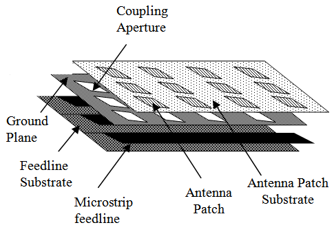 | Figure 7. Aperture-coupled Patch Antenna Array System |
3.1. Scan Blindness and Coupling between Antenna Elements
The electromagnetic interaction between the antenna elements in an antenna array results in mutual coupling. In addition to the impact of spatial correlation due to the propagation environment on the capacity of Multiple-Input Multiple-output (MIMO) channel, the coupling between antenna elements of the transmitter and receiver also has impacts on the capacity of a given communication channel. An antenna phased array network can take different forms but comprises the principal units shown in Figure 8.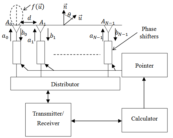 | Figure 8. General structure of antenna array network |
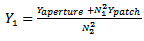
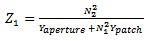
The presence of several radiating elements results in coupling between each other. As a result, a fraction of the incident signal on each element is reflected back to the distributor. These two signals are related by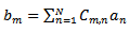 | (47) |
where  is the reflected signal of element
  is the incident signal of element n and the coefficients
  characterise the coupling coefficient matrix.In a uniform linear antenna array
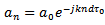 | (48) |
 | (49) |

 and d is the distance between two elements. The reflected signal on the element m thus becomes
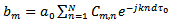 | (50) |
The characterising reflection coefficient is then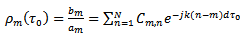 | (51) |
The coupling coefficients depend only upon the distance between two successive elements  They can therefore be described by the following form [14]
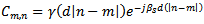 | (52) |
where  is a decreasing function of distance. Equation (51) subsequently becomes
 | (53) |
The measure of the coupling coefficient therefore permits the deduction of the reflection coefficients.The phenomenon of scan blindness manifests when almost all the incident signal is reflected back, giving rise to a relection coefficient magnitude of unity. This explanation can be deduced fron equation (53).It can be seen that the magnitude of the reflection coefficient is maximum when | (54) |
Having established the relationship between the coupling coefficients, the reflection coefficients, and scan blindness, it is evident that the knowledge of the coupling between the antenna elements will describe the state of the others.Among the benefits derived from Transmission line method of analysis is the ease in calculating the coupling coefficients. Figure 9 shows the circuit arrangement for achieving this.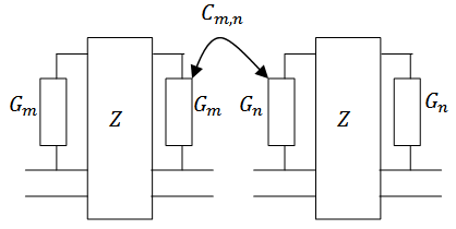 | Figure 9. Equivalent circuit showing coupling between two antenna elements |
In a uniform linear array it is sufficient to know the coupling coefficient between any two elements only, and by extrapolation the total coupling of the entire array network can be determined.The effect of mutual coupling is serious if the element spacing is small. It will affect the antenna array mainly in the following ways:1. Change the array radiation pattern2. Change the received element voltages3. Change the matching characteristic of the antenna elements (change the input impedances)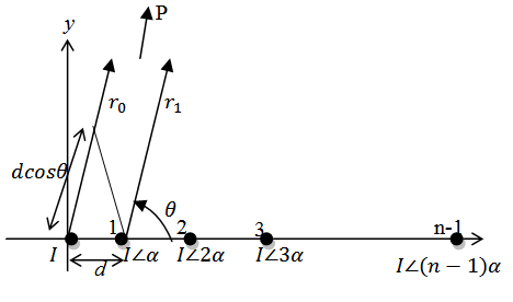 | Figure 10. n-element antenna array |
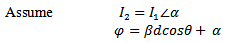 Array Factor [15]
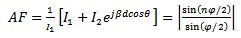 | (55) |
where n is the number of antenna elements.
4. Simulation Results and Evaluation
In practice, IEEE 802.11 WiMAX standards consist of 3.5-GHz (3.3–3.6 GHz) and 5.5-GHz (5.25–5.85 GHz) frequency bands. The resulting input impedance, return loss and radiation patterns, for coupled and uncoupled arrays, are simulated at 5 GHz centre frequency using MATLAB. The results are shown in Figures 11 to 14.Maximum bandwidth can be achieved by aperture coupling, at an input impedance of around 50Ω. Figure 11 shows simulated input impedance of around 50Ω between 4.95 – 5.0 GHz.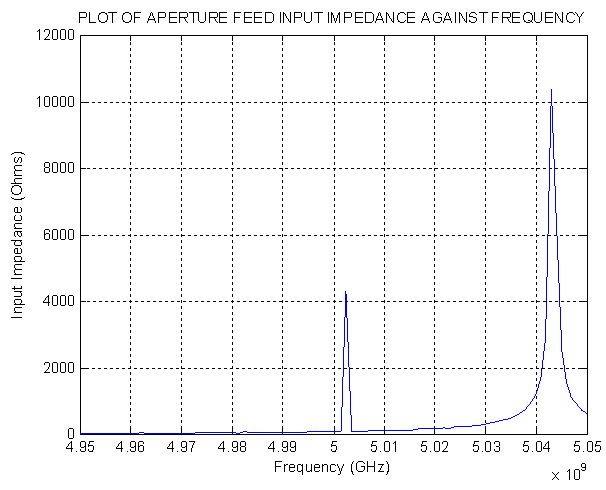 | Figure 11. Input impedance of Aperture-feed patch antenna at centre frequency of 5GHz |
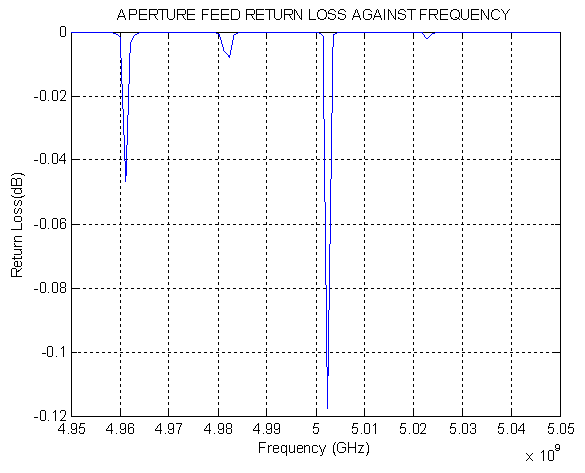 | Figure 12. Return Loss of Aperture-feed patch antenna at centre frequency of 5GHz |
Using coupled dipoles characterized using full-wave electromagnetic analysis, reveal that mutual coupling between antennas significantly reduced the radiation efficiency of the antennas. This is validated by Figures 13 and 14.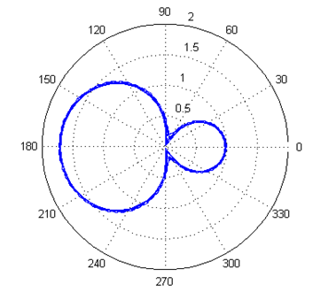 | Figure 13. Radiation pattern of antennas with no coupling |
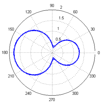 | Figure 14. Radiation pattern of coupled antennas |
5. Conclusions
Selection of the feeding technique for a microstrip patch antenna is an important decision because it affects the bandwidth and other parameters. A microstrip patch antenna excited by different excitation techniques gives different bandwidth, different gain, different efficiency etc. Aperture coupled antennas are advantageous in arrays because they electrically isolate the feed and phase shifting circuitry from the patch antennas. The disadvantage is the required multilayer structure which increases fabrication complexity and cost.When compared to standard full-wave methods usually adopted in literature, the proposed approach significantly reduced the computation time, so providing an accurate procedure to perform efficient parametric analysis on the aperture-coupled patch antennas.
References
| [1] | T. Dunga et al; “Comparison of Circular and Rectangular Microstrip Patch Antennas”, IJCEA vol.2 Issue 4, pp. 187-197, July 2011. |
| [2] | Q. Zhang, Y. Fukuoka, T. Itoh., “Analysis of a Suspended Patch Antenna excited by an Electromagnetically coupled Microstrip Feed” IEEE Transaction on Antennas and Propagation, Vol.33, n*8, August 1985, pp. 895-899. |
| [3] | J.R. James, P.S. Hall, C. Wood, “Microstrip Antennas” Peter Peregrinus Ltd, London 1981. |
| [4] | M. Hindi, J.P. Daniel, C. Terret., “Transmission Line Analysis of Aperture-Coupled Microstrip Antenna.” Electronic Letters, 31st August 1989, Vol. 25 n*18, pp. 1229-1230. |
| [5] | M. Helier “Modele de Cavite pour Resonateurs Microruban Rectangulaires”, Polycopie de lÉNSEEIHT, 1991. |
| [6] | S. Drabowitch, C. Ancona “Antennes 2: Applicaions.” Mason 1986. |
| [7] | Robert W. Heath, Jr., Member, (2005), IEEE, and David J. Love Member, IEEE “Multimode Antenna Selection for Spatial Multiplexing Systems With Linear Receivers” IEEE transactions on signal processing, 53(8), pp 30423056. |
| [8] | Ramya Bhagavatulay, Robert W. Heath Jr.y, and Kevin Linehan, (2006), “Performance evaluation of MIMO base station antenna designs” Research article, pp 115. |
| [9] | Yang yang, Rick Blum, Sana sfar , (2009), “Antenna selection for MIMO systems with closely spaced antennas” EURASIP Journal of wireless communications and networking, doi:10.1155/2009/739828. |
| [10] | Adarsh B. Narasimhamurthy and Cihan Tepedelenlioglu, (2005), Member, IEEE,” Antenna Selection for MIMO OFDM Systems with Channel Estimation Error” IEEE transactions on vehicular technology, 58(5), pp 22692278. |
| [11] | D. Orban and G.J.K. Moernaut “The Basics of Patch Antennas, Updated” September 29, 2009 edition of the RF Globalnet (www.rfglobalnet.com) newsletter. |
| [12] | X.L. Bao and M.J. Ammann X.L. Bao and M.J. Ammann (2007), patch slot antenna with 53% input impedance bandwidth” Electronics Letters, 43(3), 146147. |
| [13] | K. Jagadeesh Babu, Dr. K.Sri Rama Krishna, Dr.L.Pratap Reddy, (2010), A Modified E Shaped Patch Antenna For MIMO Systems, International Journal on Computer Science and Engineering, 2(7), pp 24272430. |
| [14] | Matthew L. Morris and Michael A. Jensen, (2005), Senior Member, IEEE “Network Model for MIMO Systems With Coupled Antennas and Noisy Amplifiers,” IEEE Transactions on antennas And Propagation, 53(1), pp 545552. |
| [15] | C.U. Ndujiuba, O. Oshin, N. Nkordeh “MIMO Deficiencies Due to Antenna Coupling”, International Journal of Networks and Communications 2015, 5(1): 10-17 DOI: 10.5923/j.ijnc.20150501.02. |
 Abstract
 Reference
 Full-Text PDF
 Full-text HTML