-
Paper Information
- Paper Submission
-
Journal Information
- About This Journal
- Editorial Board
- Current Issue
- Archive
- Author Guidelines
- Contact Us
International Journal of Electromagnetics and Applications
p-ISSN: 2168-5037 e-ISSN: 2168-5045
2015; 5(2): 80-89
doi:10.5923/j.ijea.20150502.02
Shielding Effectiveness of Rectangular Enclosure with Apertures on Two Different Sides
 Abstract
 Reference
 Full-Text PDF
 Full-text HTML
G. Kameswari , P. V. Y. Jayasree
PhD Scholar, Department of ECE, GIT, GITAM University, Visakhapatnam, A.P., India
Correspondence to: G. Kameswari , PhD Scholar, Department of ECE, GIT, GITAM University, Visakhapatnam, A.P., India.
| Email: |  |
Copyright © 2015 Scientific & Academic Publishing. All Rights Reserved.
On account of the significance of strength against electromagnetic obstruction in cutting edge life, the shielding effectiveness of a rectangular cavity with gaps on front and rears lighted by the plane electromagnetic wave is demonstrated in this paper. In the demonstrating process, the incident angle of the plane electromagnetic wave is considered. The opening is taken as the co planar strip line and the rectangular cavity is taken as a rectangular wave guide with one gap to front end and another gap on the back end. The shielding effectiveness is ascertained utilizing transmission line hypothesis. Contrasted with different creators some time recently, this system enhances the culmination of the model and processing rate which supplies great reference for designing practice.
Keywords: Different sides, Plane electromagnetic wave, Rectangular aperture, Rectangular cavity, Shielding effectiveness
Cite this paper: G. Kameswari , P. V. Y. Jayasree , Shielding Effectiveness of Rectangular Enclosure with Apertures on Two Different Sides, International Journal of Electromagnetics and Applications, Vol. 5 No. 2, 2015, pp. 80-89. doi: 10.5923/j.ijea.20150502.02.
Article Outline
1. Introduction
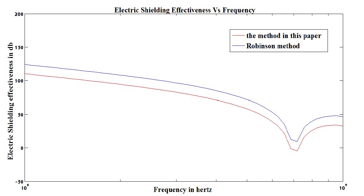
- WITH the improvement of science and innovation, electromagnetic environment is turning out to be more unpredictable in our lives. Keeping in mind the end goal to oppose the impact of electromagnetic obstruction, electromagnetic shielding is a work in progress and utilized as a part of different fields. Though there are many numerical methods that can obtain accurate simulation data of electromagnetic calculation [1-4], the long calculation time and huge computation make its overkill for the applications of guiding engineering practice. So, the analytic method wins general concern of researchers. Now, there are two types of analytical methods mainly: the method based on Bethe aperture coupling theory [5], [6] and the method based on transmission line theory [7], [8]. The second type is discussed further in this paper. M. P. Robinson introduced transmission line theory into the electromagnetic shielding field first, and researched the shielding effectiveness of the rectangular cavity with the aperture irradiated by the plane electromagnetic wave [9], [10] in 1996, but the higher order modes of the electromagnetic field in the cavity, the polarization angle, and the incidence angle were ignored in the model. T. Konefal introduced an intermediate-level circuit model method in 2005 [11], but there are much more integral operations in the model which can increase the calculation time, and there is only one face with the aperture. F. A. Po’ad extended M. P. Robinson’s model, and made the center of aperture free on the x-axis in 2006 [12-14]. Following Farhana Ahmad Po’ad, Shi Dan extended the model further, made the center of aperture free on the x- and y-axes and considered higher order modes of the electromagnetic field in the cavity in 2009 [15], [16]. Recently, J. R. Solin proposed a method for the field excited in a perfectly conducting rectangular cavity with a small aperture by an external field acting on the aperture [17], [18]. The model is becoming more and more perfect with the deepening of research, but the calculation of shielding effectiveness has always been limited to the center line of the front panel aperture in the cavity. In order to meet the actual conditions better, the cavity with apertures on two different side front and back panels are considered in the model and the shielding effectiveness is calculated.
2. Mathematical Formulation
- Rectangular cavity with apertures on two different side front and back panels is shown in Figure 1.
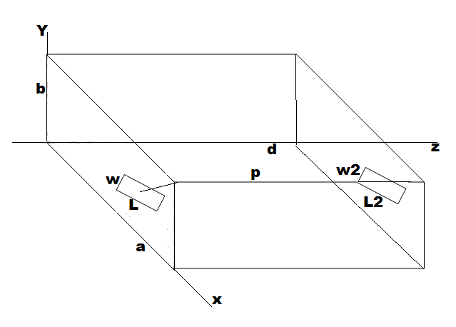 | Figure 1. Rectangular enclosure with two apertures on front and back panels |
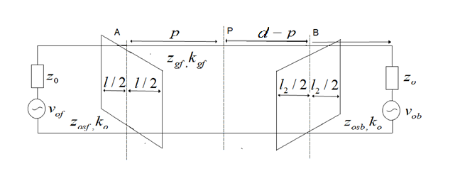 | Figure 2. Equivalent Circuit of rectangular enclosure |
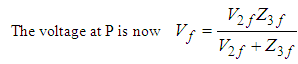
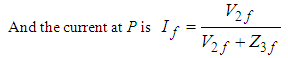
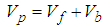
 . We proceed by first finding equivalent impedance for the front panel aperture and then using simple transmission line theory to transform all the voltages and impedances to point P. Next we proceed by finding equivalent impedance for the back panel aperture and then using simple transmission line theory to transform all the voltages and impedances to point P. Since both the apertures are in parallel, the final voltage at ‘p’ is the sum of Vpf and Vpb.
2.1. Electrical and Magnetic Shielding Effectiveness of Front Panel Aperture
- The aperture characteristic impedance is given by Gupta et al. [19-20] as
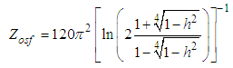 | (1) |
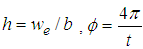 and the effective width
  is
is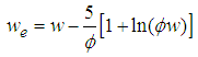 | (2) |
 , we transform the short circuits at the ends of the aperture through a distance l/2 to the center. This is represented by point A in the equivalent circuit. It is mandatory here to include a factor l/a to account for the coupling between the aperture and the enclosure.
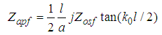 | (3) |
 | (4) |
 | (5) |
 | (6) |
 | (7) |
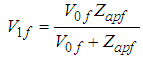
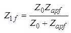
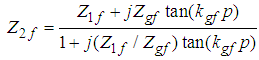
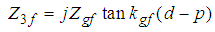
 Then V1f, Z1f and the short circuit at the terminal of the wave guide to P are transformed by attributing an equivalent voltage V2f, source impedance Z2f and load impedance Z3f.
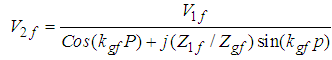 | (8) |
 | (9) |
 | (10) |
 | (11) |
 | (12) |
2.2. Electrical and Magnetic Shielding Effectiveness of Back Panel Aperture
- The back panel aperture characteristic impedance
 and aperture impedance
  are obtained by replacing
  by
by  and
and  by
by  in equations (2) & (3).According to Thevenin’s theorem fusing Z0b, V0b and Zapb results in an equivalent voltage
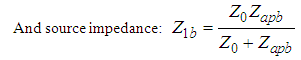 | (14) |
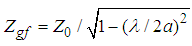
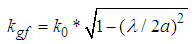
 and propagation constant
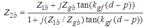
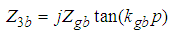
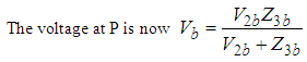
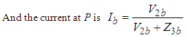
  .Then V1b, Z1b and the short circuit at the terminal of the wave guide to P are transformed by attributing an equivalent voltage V2b, source impedance Z2b and load impedance Z3b.
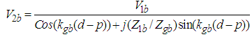 | (15) |
 | (16) |
 | (17) |
 | (18) |
 | (19) |
 | (20) |
 | (21) |
 | (22) |
3. Results
3.1. Electric Shielding Effectiveness
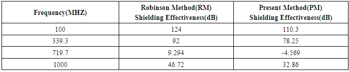
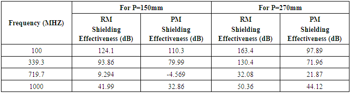
- We consider a rectangular box of size (300X120X300) mm3.The box is assumed to be excited by a plane wave with normal incidence for studying the SE of a rectangular box with a front panel aperture as the case (a) and front & back panel apertures as case (b). Figure 3a & Figure 3b shows the variation of the electric shielding effectiveness as a function of frequency by using TLM method. In both the cases the enclosure resonates at approximately 700MHZ frequency and SE decreases with frequency below the resonant frequency. The overall shielding effectiveness has decreased by 14 dB in case (b) when compared to the case (a). The comparison between the case (a) and case (b) is shown in Table 1.
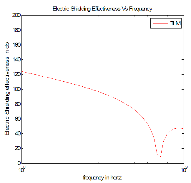 | Figure 3a. Calculated SE using transmission line formulation in 300X120X300 box with 100X5 box with 100X5 front panel aperture front panel aperture |
 | Figure 3b. Calculated SE using transmission line formulation in 300X120X300 box with two 100X5 box with two 100X5  apertures at front and back panels apertures at front and back panels |
|
 | Figure 4a. Calculated SE at three different positions in 300X120X300  box with 100X5 box with 100X5  front panel aperture front panel aperture |
 | Figure 4b. Calculated SE at three different positions in 300X120X300  box with two 100X5 box with two 100X5  apertures at front and back panels apertures at front and back panels |
|
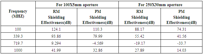
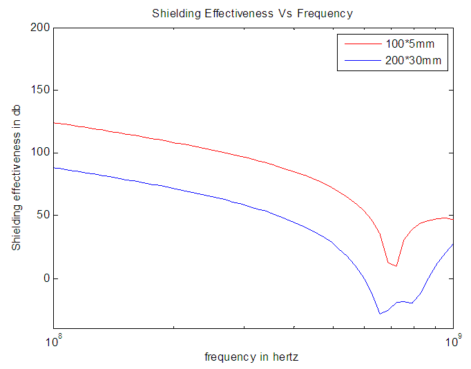 | Figure 5a. Calculated SE at center in 300X120X300  box with two 100X5 box with two 100X5  and 200X30 and 200X30  apertures at front panel only apertures at front panel only |
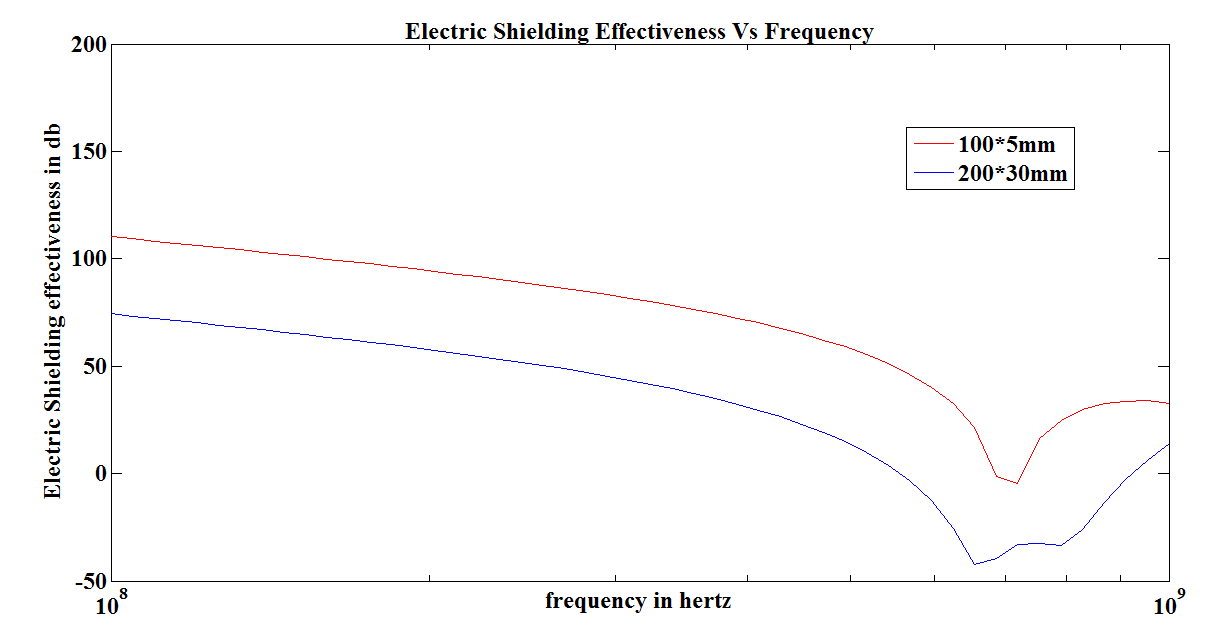 | Figure 5b. Calculated SE at center in 300X120X300  box with two 100X5 box with two 100X5  and 200X30 and 200X30  apertures at front & back panels apertures at front & back panels |
|
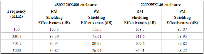
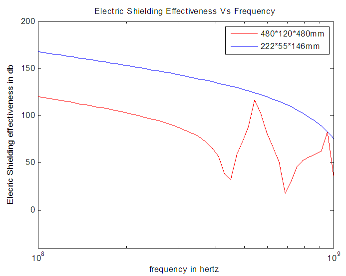 | Figure 6a. SE of 222X55X146  and 480X120X480 and 480X120X480  boxes with the same aperture of 100X5 boxes with the same aperture of 100X5  size at front panel size at front panel |
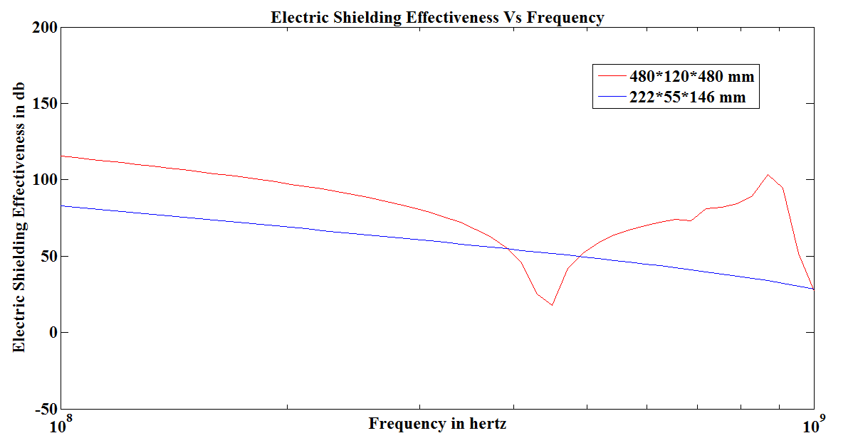 | Figure 6b. SE of 222X55X146  and 480X120X480 and 480X120X480  boxes with the same aperture of 100X5 boxes with the same aperture of 100X5  size at front and back panels size at front and back panels |
|
3.2. Magnetic Shielding Effectiveness
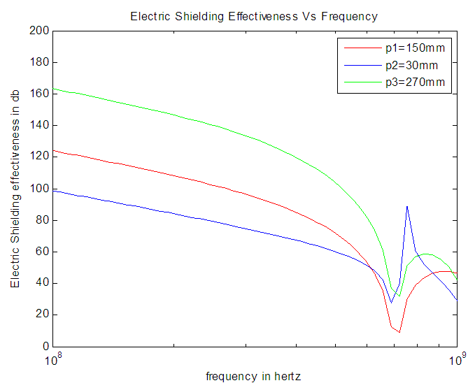
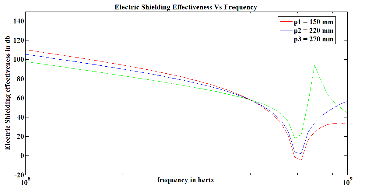
- We consider a rectangular box of size (300X120X300) mm3.The box is assumed to be excited by a plane wave with normal incidence for studying the SM of a rectangular box with a front panel aperture as the case (a) and front & back panel apertures as case (b). When the magnetic shielding effectiveness is calculated at three different positions within the (300X120X300) mm3 enclosure with an (100X5) mm2 front panel aperture at p=150, 200 and 270mm. The enclosure resonance at 700MHz can be seen at p = 200mm and p=270mm, but is less evident at the center of the box (p=150mm). This is expected from the mode structure of the resonance. At low frequencies, SM increases with distance from the aperture (as does SE), but is almost independent of frequency as shown in Figure 7a. But it is observed that SM decreases with the increased distance when two (100X5) mm2 apertures taken at front and back panels as shown in Figure 7b.
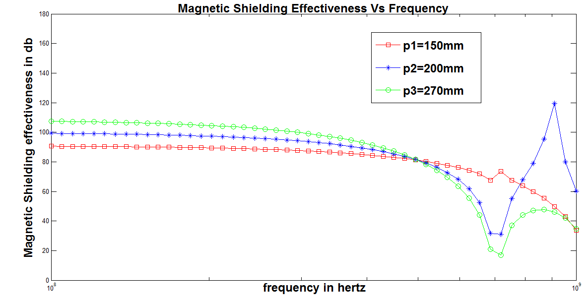 | Figure 7a. Calculated SM at three different positions in 300X120X300  box with 100X5 box with 100X5 front panel aperture front panel aperture |
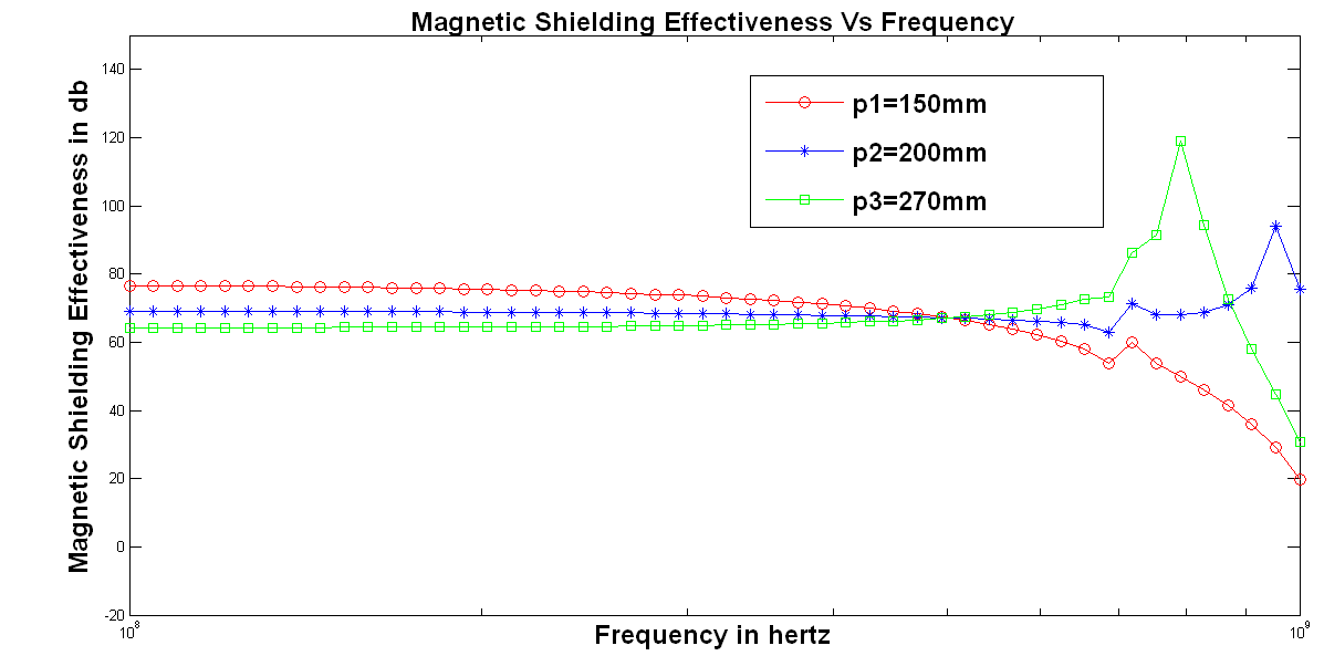 | Figure 7b. Calculated SM at three different positions in 300X120X300  box with two 100X5 box with two 100X5 apertures at front and back panels apertures at front and back panels |
4. Conclusions
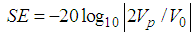
- The shielding effectiveness of a rectangular cavity with apertures in different panels (front & back) irradiated by the plane electromagnetic wave is modeled in this paper and the results were compared with single aperture at front panel only. The calculation of electric shielding using transmission line depends on the frequency and applied field’s polarization and the enclosure’s dimensions and aperture(s) dimensions, the quantity and position of the apertures within the enclosure. Compared to the referenced authors, the method proposed in this paper improves the completeness of the model and the computation speed which supplies good reference for engineering practice. But the simulation results show that the overall shielding effectiveness is decreased by 14dB compared to the referenced author.