-
Paper Information
- Paper Submission
-
Journal Information
- About This Journal
- Editorial Board
- Current Issue
- Archive
- Author Guidelines
- Contact Us
International Journal of Electromagnetics and Applications
p-ISSN: 2168-5037 e-ISSN: 2168-5045
2015; 5(1): 13-21
doi:10.5923/j.ijea.20150501.03
Bandwidth Enhancement of Unidirectional Planar Antenna Using Closely Spaced Reactive Loading Technique
 Abstract
 Reference
 Full-Text PDF
 Full-text HTML
Mahesh B. Toshniwal, Veeresh G. Kasabegoudar
P. G. Dept., MBES College of Engineering, Ambajogai, India
Correspondence to: Mahesh B. Toshniwal, P. G. Dept., MBES College of Engineering, Ambajogai, India.
| Email: |  |
Copyright © 2015 Scientific & Academic Publishing. All Rights Reserved.
In this paper a broadband unidirectional planar microstrip antenna is presented. The proposed geometry consists of rectangular loop having two gaps and metallic strips. Although, the rectangular loop in the geometry introduces a good directionality but offers a narrow bandwidth. This problem is addressed by placing the metallic strips which induce a new resonant frequency results in the improvement of impedance bandwidth. The geometry was optimized using Ansoft’s HFSS which is commercially available electromagnetic (EM) software, and tested practically to validate the simulation results. The measured results indicate 66.57% impedance bandwidth with good gain across the band. Measured results fairly agree with the simulated data.
Keywords: Broadband MSAs, Closely spaced loading method, Unidirectional planar antennas
Cite this paper: Mahesh B. Toshniwal, Veeresh G. Kasabegoudar, Bandwidth Enhancement of Unidirectional Planar Antenna Using Closely Spaced Reactive Loading Technique, International Journal of Electromagnetics and Applications, Vol. 5 No. 1, 2015, pp. 13-21. doi: 10.5923/j.ijea.20150501.03.
Article Outline
1. Introduction
- The need for wideband and low-profile unidirectional antennas with good electrical characteristics is ever demanding. Most of these antennas offer omni-directional radiation characteristics. However, antennas are required to have unidirectional patterns for some applications like point to point communication. Low profile antennas with wideband characteristics are also desired in almost all modern wireless communication systems [1]. To improve the signal reception some mobile applications are also required avoiding a null in the main direction of the radiation pattern; which in turn provides a quasi-unidirectional pattern [2]. An antenna with three bowtie dipole elements is proposed based on the idea of log-periodic antenna [3]. The wire dipole elements in the log-periodic antenna are replaced by bowtie dipole elements for larger impedance bandwidth with element number as small as possible [4]. Various structures of printed antenna have been developed to minimize the size of the structure, improving impedance matching, wideband characteristics [5, 6].In general, all antennas comprising planar or curved surface radiators or their variations and at least one feed are termed ‘planar antennas’. To obtain the unidirectional radiation characteristics traditional printed small antennas may not be a good selection. Despite of large size the tapered slot antenna gives more bandwidth as its lower frequency depends on its size [7].For the wideband performance planar Yagi antennas were designed, but they also consist of large size [8, 9]. For Enhancement of uni-directionality the cavity back structures or reflectors were reported in [10, 11]. This also results in increase in size of antenna. In general, all antennas comprising planar or curved surface radiators or their variations and at least one feed are termed ‘planar antennas’. Some of the designs use an antenna element with ground plane at the top, but they are electrically large for the small antenna [12, 13].The design of the rectangular loop is taken from [14]. A novel vertical planar printed antenna with improvement in back-lobe radiation and symmetrical radiation patterns in the E- and H-planes presented in [15]. The folded dipole driver is comprised of a folded dipole and a microstrip feedline which functions as an internal balun to mainly determine its wide impedance bandwidth [16]. The H-shaped resonator structure was reported to obtain a higher gain and better radiation patterns over the whole band in [17]. A microstrip feedline acts as an internal balun to enhance its operating band. The effect of the spacing between the reflector and the driver on the performance of a conventional Yagi antenna is as presented in [18]. In this paper, a broadband unidirectional antenna based on closely spaced loading method is presented. The geometry and working of the antenna is similar to [19]. However, by adding reacting stubs, the desired range of impedance bandwidth is obtained. The proposed antenna dimensions have been calculated as suggested in [20]. The detailed geometry of the antenna is discussed in section 2. Section 3 covers the geometry optimization using Ansoft’s HFSS v.11 [21] and, the various results obtained from this study are presented at the end of this section. Experimental validations and discussions of the implemented geometry are presented in Section 4. Finally, the conclusions of this study are presented in Section 5.
2. Antenna Geometry
- The geometry proposed in this paper is shown in Figure 1. It works on the principle of closely spaced reactance loading method which is explained in the following subsection. The optimization procedure is covered in detail in Section 3.
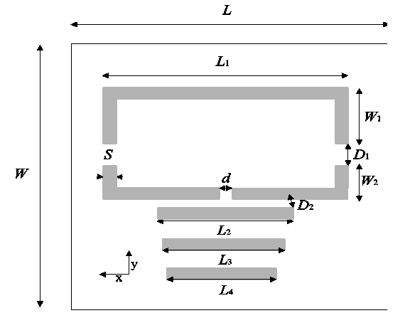 | Figure 1. Geometry of the proposed antenna |
2.1. Closely Spaced Loading Method
- A drop in radiation resistance in the Yagi antenna is due to spacing of elements of the antenna, which results in the low efficiency. While decreasing the spacing between the antenna elements leads to decrease in radiation resistance, and also loss resistance remains the same [19]. In this method the effect of the spacing between the director and the driver is studied. The resonant frequency f is determined by the relation [20]:
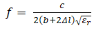 | (1) |
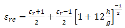 | (2) |
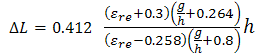 | (3) |
2.2. Broadband Unidirectional Antenna Design
- The Figure 2.1 shows the proposed design of the antenna. Antenna’s overall dimensions are 60×50×0.8 mm3. The substrate used for simulations is FR4 with dielectric constant of 4.4 and height equal to 0.8mm. The antenna is a combination of rectangular loop and metallic strips. The size of rectangular loop and metallic strips is S = 2mm. This antenna is regarded as a printed Yagi antenna. The rectangular loop and metallic strips are on the same side of the substrate. The loop of the antenna exhibits the unidirectional feature, while closely loaded strip offers the wideband feature of the antenna.Typical dimensions of the proposed geometry are presented in Table 1.
|

3. Geometry Optimization and Discussions
- In this section parametric study is conducted to optimize the proposed antenna. The key design parameters used for the optimization are length of the metallic strips (L2, L3, and L4), gap between the strips (D2), length of the reflector (L1), width of reflector arms (W1) and driver arms (W2) and gap between reflector and driver element (D1). The detailed analysis of these parameters is investigated in the following subsections. All simulations were carried out with HFSS software which is a Finite Difference Time Domain (FDTD) based electromagnetic (EM) software.
3.1. The Effect of the Metallic Strips
- In this study three strips of lengths L2, L3, and L4 have been placed below the rectangular loop. The purpose of adding these strips serve reactance loading. It is well understood that reactance loading is one of the popular techniques of enhancing the microstrip antennas bandwidth [19]. The simulated reflection coefficients of the rectangular loop antenna with different length and position of the metallic strip are shown in Figure 2 (a). The upper resonant frequency is determined by the length of the metallic strip where as lower resonant frequency is decided by rectangular loop. It is observed that when the length L2 increases, the upper resonant frequency shifts towards lower end of the band. In the further study, L3 and L4 have been varied in steps 1mm to investigate effect of these two parameters on the geometry of the antenna. From the study it was observed that L3=19mm and L4 =17mm offer the best possible bandwidth (66.57%).In yet another effort, the spacing between rectangular loop and adjacent metallic strip (D2) is varied from 0.4mm to 1.0mm in steps of 0.2mm. Return loss characteristics of this study are presented in Figure 2(d). It shows that the performance of the proposed planar antenna is also strongly affected by the spacing. The impedance matching is significantly improved when the spacing decreases. From Figure 2(d), it is noticed that D2=0.5mm offers optimum performance.
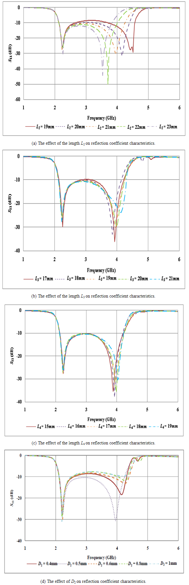 | Figure 2. Effect of varying metallic strips parameters on the reflection coefficient |
3.2. Effect of Rectangular Loop Parameters on Antenna Geometry
- Here, the parameters of the rectangular loop L1, W1, W2, and D1 are considered (one at a time) to investigate each of these parameters on the antenna’s performance. The length of reflector (L1) is changed in steps of 1mm keeping all other parameters constant. Return loss characteristics of these changes are given in Figure 3. (a). The width of both arms (W1 and W2) of rectangular loop are also taken into account to understand their effect on the reflection coefficient characteristics. At first reflector arm’s width (W1) is varied in steps of 1 mm and after optimizing W1, W2 is varied in steps of 0.5mm. From these studies, the optimum values of these two parameters are found to be 10mm and 6mm respectively. Further, gap between reflector and driver (D1) was optimized at D1=4mm. From the simulations, it can be summarized that the structure of the rectangular loop mainly determines the lower resonant frequency. Meanwhile, the metallic strips have relatively larger effect on the upper frequency. The upper resonant point is determined by the length of the metallic strip. The impedance matching in whole band mainly depends on the length and the position of the metallic strips.
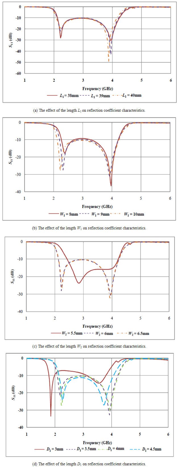 | Figure 3. Effect of the rectangular loop |
4. Experimental Validation of the Geometry and Discussions
- The geometry shown in Figure 1 with its optimized dimensions presented in Table 1 was fabricated and tested. The substrate used for the fabrication is the FR4 glass epoxy with dielectric constant of 4.4, and a thickness of 0.8 mm. A photograph of the fabricated prototype is shown in Figure 4 and gain of the antenna is shown in Figure 5. From Figure 6 it may be noted that the measured results fairly agree with the simulated values. The radiation patterns are presented at selected frequencies in the operating band to demonstrate the proper working of antenna at desired bands of frequencies. From the patterns it can be noticed that the radiation characteristics exhibit maximum at bore-sight angles. Also, the E-plane patterns have better -20dB cross polarizations where as H-plane cross polarizations exhibit better than -40dB. Besides this the radiation patterns are uniform throughout the band of operation.
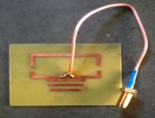 | Figure 4. Fabricated prototype |
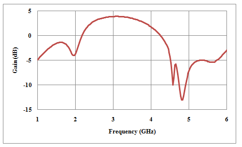 | Figure 5. Gain Vs. Freq. plot |
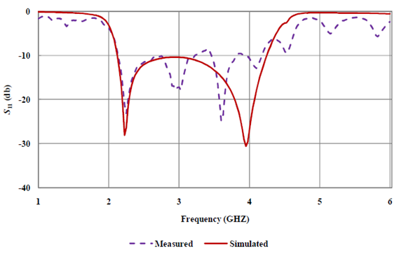 | Figure 6. S11 vs. frequency comparison of measured and simulated data |
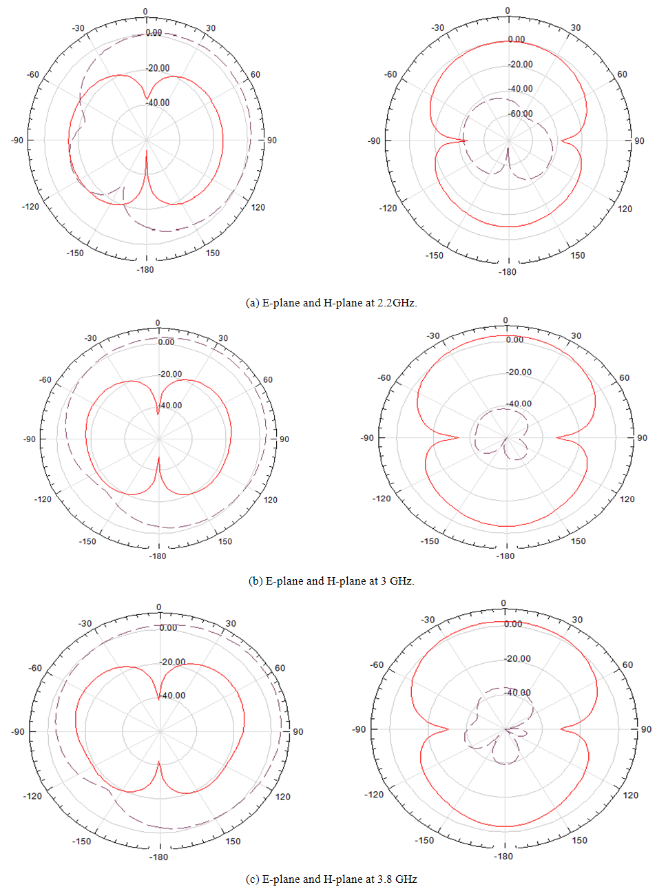 | Figure 7. E and H plane radiation pattern at different frequencies in operating band |
5. Conclusions
- In this paper a broadband unidirectional antenna based on closely spaced loading method with metallic strips is presented. By introducing additional metallic strips, the impendence decreases at the high resonant frequency. Lower end frequency can be decided by loop parameters where as higher end frequency is solely decided by strips parameters. The impendence matching is greatly improved between the two resonant peaks, by tuning the length and the position of the metallic strip. The bandwidth is therefore enlarged. Finally, through the optimizations of the parameters of both the rectangular loop and the strips, the antenna was optimized. The presented results show that an impedance bandwidth of 66.57% was achieved.