-
Paper Information
- Previous Paper
- Paper Submission
-
Journal Information
- About This Journal
- Editorial Board
- Current Issue
- Archive
- Author Guidelines
- Contact Us
International Journal of Electromagnetics and Applications
p-ISSN: 2168-5037 e-ISSN: 2168-5045
2014; 4(3): 70-76
doi:10.5923/j.ijea.20140403.03
Ultra-Wideband Monopole Antenna with Multiple Notch Characteristics
 Abstract
 Reference
 Full-Text PDF
 Full-text HTML
Vivek M. Nangare, Veeresh G. Kasabegoudar
P. G. Dept., MBES College of Engineering, Ambajogai, India
Correspondence to: Vivek M. Nangare, P. G. Dept., MBES College of Engineering, Ambajogai, India.
| Email: |  |
Copyright © 2014 Scientific & Academic Publishing. All Rights Reserved.
In this paper an ultra-wideband (UWB) monopole antenna with notches at four frequencies is presented. Notch characteristics at desired frequencies are obtained using small rectangular metallic strips. The notch frequency can be varied with the help of length of rectangular metallic strip. The overall dimensions of the proposed antenna are 34mm×27 mm ×0.8mm. The antenna operates in the frequency range from 3.1-10.6 GHz covering FCC defined UWB band. Moreover, the proposed antenna provides good radiation patterns across the working bands and a relatively good gain over the entire frequency band excluding the rejected bands. Measured results fairly agree with the simulated characteristics.
Keywords: Ultrawideband Antenna, Monopole Antenna, Notch Antenna
Cite this paper: Vivek M. Nangare, Veeresh G. Kasabegoudar, Ultra-Wideband Monopole Antenna with Multiple Notch Characteristics, International Journal of Electromagnetics and Applications, Vol. 4 No. 3, 2014, pp. 70-76. doi: 10.5923/j.ijea.20140403.03.
Article Outline
1. Introduction
- Since the U.S. Federal Communication Commission (FCC) authorized the unlicensed use of the ultrawideband (UWB) in (3.1-10.6) GHz in February 2002, significant research activities and interests have been used in academic and industrial fields recently to explore various UWB antennas [1]. There are many challenges in design of ultra-wideband (UWB) antennas. Some of them are radiation stability, compact size, low manufacturing cost & electromagnetic interference. The frequency range for UWB systems approved by the FCC will cause interference to the existing wireless communication systems, such as the IEEE 802.16 WiMAX system at 3.5 GHz (3.3-3.7 GHz) and the IEEE 802.11a wireless local area network (WLAN) system at 5.2/5.8 GHz (5.15-5.825 GHz) and dedicated short-range communication (DSRC) for IEEE 802.11p [2]. To avoid interference from coexisting systems, it is highly desirable to introduce notch filters internally or externally. By introducing the notch filters internally, the space and cost can be minimised significantly rather than adding them externally [2].There are several methods have been reported in literature to introduce a notch characteristic in the UWB antenna [2-20]. A few of them are achieved by addition of U shaped [3], H shaped slot [4], C shaped [5], and L shaped [6, 7] slots in the patch or radiating ground plane. From these efforts, one can achieve the notch characteristics in the operating band [3-7]. Rather using different shaped slots, some of the researchers used complementary split ring resonator (CSRR) [8], complementary spiral loop resonator (CSLR) [9], dual arm spiral resonator [10], and addition of parasitic elements for notch bands excitation [6-9]. In all these methods resonance frequency is varied by adjusting the slot dimensions. However, these methods are unsuccessful in varying lower end frequency of WLAN. Also, these methods require changing the designs of an antenna. Hence, without disturbing the existing antenna design, band notch structures using capacitively loaded loop resonator (CLL) was achieved in [2]. Each CLL element is having high quality factor and compact size. But it is difficult to put these CLL elements in the slot of antenna itself. Also, the area required for each CLL element may vary with frequency.Therefore, in this work, an ultra-wideband (UWB) monopole antenna with notches at four frequencies is presented. The presented antenna geometry and its working are similar to the antenna presented in [2]. However, the antenna proposed here uses very simple reactive stubs to excite the multiple notches at desired frequencies. Notch band characteristics are achieved with rectangular strips which are simple in design and compact in sizes. By adjusting the length/width, and position of rectangular strip the notch frequency can be varied. The proposed antenna geometry and its dimensions are presented in Section 2. The geometry optimization is carried out using Ansoft’s HFSS v.13 [21] and the various results obtained from this study are presented at the end of this section. In Section 3, the fabricated prototype and the optimized values obtained from EM simulations are compared. Finally, the Conclusions of this study are presented in section 4.
2. Antenna Geometry with and without Notch Frequency
- Figure 1(a) & (b) shows the basic geometry of proposed triangular monopole antenna for UWB operation. The antenna is backed by defected ground structure (DGS) to match the antenna’s impedance. The substrate used for the study is FR4 epoxy resin material with relative dielectric constant (εr) equal to 4.4 and height of the substrate (h)=0.8mm. The overall dimensions of antenna are 34mm×27mm×0.8mm. The antenna is excited by a microstrip line feed. Typical dimensions of the proposed geometry are presented in Table 1.
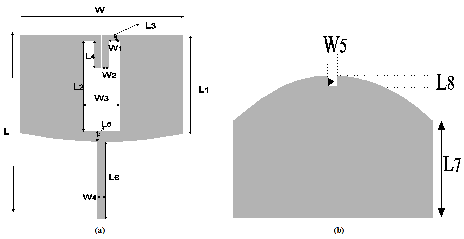 | Figure 1. UWB antenna (a) Front side (b) Back side |
|

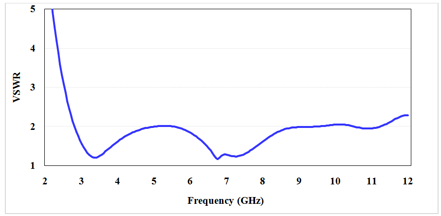 | Figure 2. VSWR vs. frequency plot of antenna geometry shown in Figure 1 |
2.1. Single Notch
- In order to excite a notch frequency, the single metallic strip (10mm length and 0.1mm width) is introduced and shorted to the microstrip feed line of the antenna (about 0.3mm below the corner where microstrip line and the patch border meet). This metallic strip excites a notch at 4.6 GHz. The excitation of multiple notches and modes is achieved by perturbing the currents on the patch [2]. It may be noted that the notch frequency can be tuned with the help of length and width of the introduced metallic strip. However, it was observed that varying the length results in the fine tune of the notch frequency and the change in its (strip) width results in the course variation of the notch frequency.
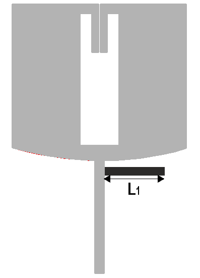 | Figure 3. Introduction of single notch using a metallic strip |
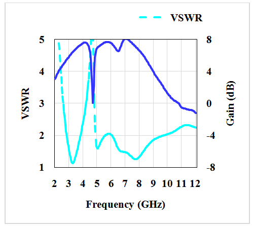 | Figure 4. VSWR, and gain vs. frequency plot of geometry shown in Figure 3 |
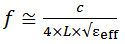 | (1) |
2.2. Dual Notches
- For exciting dual notch characteristics, one can achieve using same antenna geometry with two metallic strips of lengths 5mm and 9mm as shown in Figure 5. Input matching characteristics of the antenna are as shown in Figure 6. From the Figure 6, it may be noted that the second notch is excited at 8.5GHz nearly without affecting the first one (4.9GHz). It was observed that both notches can be shifted either left or right using strip length variations as per the exact requirement.
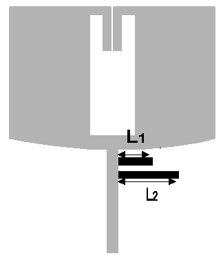 | Figure 5. Antenna geometry with dual notch characteristics |
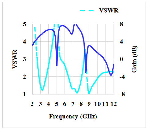 | Figure 6. Input matching characteristics, and gain vs. frequency plots of geometry shown in Figure 5 |
2.3. Triple Notches
- As explained in single and dual notch characteristics, triple notch antenna designed using placing three metallic strip lengths as indicated in Figure 7. In this design three metallic strips are used for excitation of three notches. The simulated input characteristics of the geometry shown in Figure 7 are shown in Figure 8. From Figure 8 it may be noted that three notches are excited at 4.1GHz, 5.5GHz, and at 8.5GHz. These notches are obtained by placing three strips of lengths 5mm (L1), 8mm (L2), and 11mm (L3) respectively. In all cases the width of all strips is kept 0.1mm constant.
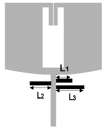 | Figure 7. Antenna geometry with triple notch characteristics |
 | Figure 8. VSWR and gain total vs. frequency plots of geometry shown in Figure 7 |
2.4. Four Notches
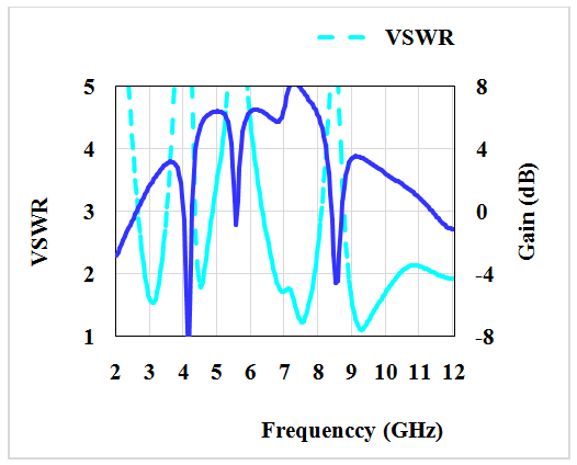
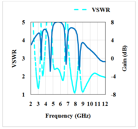
- In the final effort we introduced four metallic strips as shown in the Figure 9. The dimensions (lengths) of these strips are 4.5mm, 6.0mm, 8.0mm, and 11.0mm. For these dimensions we obtained notch characteristics at 3.8GHz, 5.1GHz, 6.9GHz, and at 9.5GHz. As explained in earlier paragraphs, these frequencies can be fine tuned with the help of lengths of these strips. It can also be noted that any one among these i.e., specific frequency of interest can also be tuned. The input characteristics of the geometry shown in Figure 9 are presented in Figure 10.
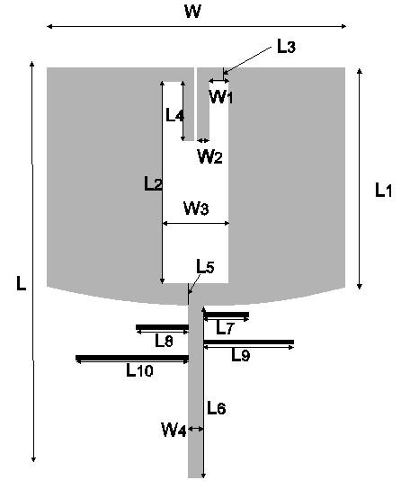 | Figure 9. Four bands notch antenna |
 | Figure 10. VSWR and gain total vs. frequency plots of geometry shown in Figure 9 |
2.5. Alternate Approach for Exciting Four Notches
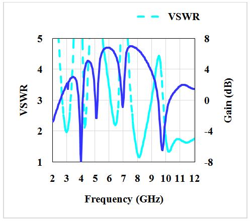
- In another effort we tried to excite the four notches as explained in earlier paragraphs (sub sections) using the geometry shown in Figure 11. Keeping the overall dimensions of the geometry constant (34mm×27mm× 0.8mm), and using only three strips as indicated in Figure 11, four notches are excited. Among four notches, the first notch is excited by the antenna geometry itself. The detailed dimensions of this geometry (Figure 11) are listed in Table 2. Three different strips with lengths of 6mm, 8.5mm, and 11.5mm are used for the excitation of notches. The four notch frequencies obtained are 3.5GHz, 4.9GHz, 6.7GHz, and at 9.3 GHz (Figure 12).
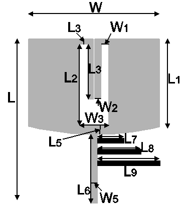 | Figure 11. Alternate geometry for four notch characteristics |
 | Figure 12. VSWR, and gain vs. frequency plots |
|

3. Experimental Validation of the Geometry and Discussions
- The geometry shown in Figure 9 with its optimized dimensions presented in Table 1 was fabricated and tested. The substrate used for the fabrication is the FR4 glass epoxy with dielectric constant of 4.4, and a thickness of 0.8 mm. A photograph of the fabricated prototype is shown in Figure 13. The VSWR comparisons of measured and simulated values are compared in Figure 14. From Figure 14 it may be noted that the measured results are fairly agreed with the simulated values. The radiation patterns are presented at selected frequencies in the operating bands (excluding notches) to demonstrate the proper working of antenna at desired bands of frequencies (Figure 15).
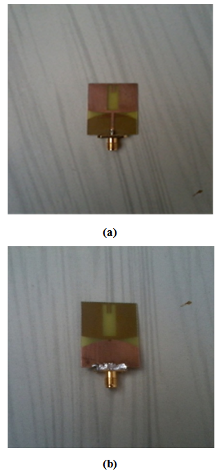 | Figure 13. Fabricated prototype (a) Front side (b) Back side |
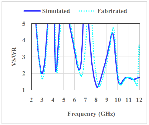 | Figure 14. VSWR vs. frequency comparisons of measured and simulated data |
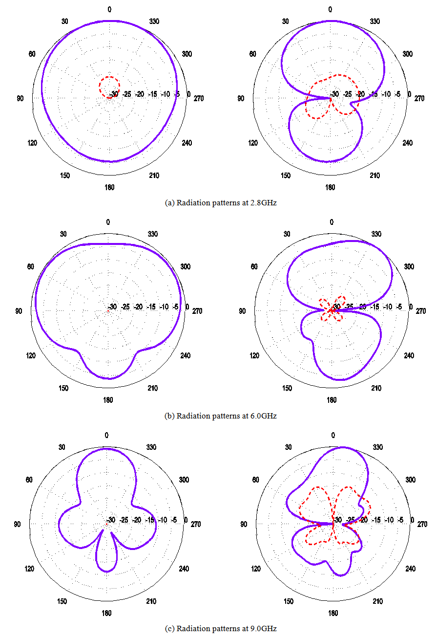 | Figure 15. Radiation patterns at various frequency points across the bands of operation. Left column: H-plane patterns; Right column: E-plane patterns. Solid lines: Co-polarizations; Dashed lines: Cross polarizations. Note: in some of the H-plane patterns cross polarisation are not seen as they are well below -30dB |
4. Conclusions
- An ultra-wideband antenna with and without notch characteristics has been presented. All geometries presented here cover the FCC defined frequency range (3.1 GHz to 10.6GHz). Designs have been presented to excite one, two, three, and four notches in the bands of operation. For this simple metallic strips were used. Also, fine tuning of notch characteristics can be achieved by varying either length or width of these metallic strips. A good gain (>7dB) was observed throughout the bands of operation. The fabricated prototype was measured and compered with the measured optimized results. A fair matching with the measured data was observed. The antenna presented here is good candidate for eliminating any unwanted or disturbing frequency in desired band.