-
Paper Information
- Next Paper
- Paper Submission
-
Journal Information
- About This Journal
- Editorial Board
- Current Issue
- Archive
- Author Guidelines
- Contact Us
International Journal of Electromagnetics and Applications
p-ISSN: 2168-5037 e-ISSN: 2168-5045
2014; 4(3): 61-69
doi:10.5923/j.ijea.20140403.02
An Alternative Look to Design of Wideband Planar Monopole Antennas Based on Parasitic Elements for C-band Wireless Applications
 Abstract
 Reference
 Full-Text PDF
 Full-text HTML
Dhirgham K. Naji
Department of Electronic and Communications Engineering, College of Engineering, Alnahrain University, Baghdad, Iraq
Correspondence to: Dhirgham K. Naji, Department of Electronic and Communications Engineering, College of Engineering, Alnahrain University, Baghdad, Iraq.
| Email: |  |
Copyright © 2014 Scientific & Academic Publishing. All Rights Reserved.
This paper presents and describes a method based on parasitic elements technique to design a compact and wideband printed elliptical monopole antenna (PEMA) for C-band wireless applications. A quarter circular-shaped parasitic loads (QCPLs) are used as parasitic elements for designing wideband PEMA. A 50Ω coplanar waveguide (CPW) line feeds this antenna and the CPW line is connected to antenna's elliptical-shaped monopole radiator. To improve the impedance bandwidth of the PEMA, two pairs of QCPLs are used; the first one is loaded to the patch and placed at the upper substrate's corner and the second one is loaded to the upper corner of CPW-ground plane. The performance of the antenna is evaluated with aid of the time domain CST Microwave Studio (MWS) simulator and confirmed independently using the frequency domain ANSOFT High Frequency Structure Simulator (HFSS). The optimized antenna has a compact size of 13 and a prototype of the antenna is fabricated and tested. The two simulators agree very well with each other and with measurement. The simulation and measurement results demonstrate that the antenna operates in the C-band (). Furthermore, the proposed antenna shows nearly omnidirectional radiation characteristics and reasonable gain in the operating band. Moreover, with a broad bandwidth, an antenna has other features; simple configuration, compactness and low fabrication cost. Therefore, this antenna can be used for C-band applications.
Keywords: Coplanar waveguide (CPW), C-band, Printed elliptical monopole antenna (PEMA), Parasitic elements
Cite this paper: Dhirgham K. Naji, An Alternative Look to Design of Wideband Planar Monopole Antennas Based on Parasitic Elements for C-band Wireless Applications, International Journal of Electromagnetics and Applications, Vol. 4 No. 3, 2014, pp. 61-69. doi: 10.5923/j.ijea.20140403.02.
Article Outline
1. Introduction
- An antenna is considered as one of important components in communication systems and it is responsible for receiving and transmitting electromagnetic waves. In particular, for modern wireless communication systems, the antenna represents the largest part and determines the physical size of the whole system. As a result, demands for antennas with miniaturized sizes, low profiles, low costs, and multiband and/or wideband for wireless communication devices increase the interest in recent years [1]. It is a well-known fact that, microstrip patch antennas (MPAs) have unique characteristics and offer several advantages that made them popular with wireless communication devices because of their outstanding physical properties, such as light weight, low profile, low production cost, conformability, versatility, reliability, and ease in fabrication and integration with solid state devices and wireless technology equipments [2, 3]. In spite of such antennas' advantages, conventional MPA shows a narrow band performance having a fractional bandwidth 2-3%. Over the last years, there are fundamentally two methods have been proposed in literatures to provide a bandwidth of the order of 10% and more; either by changing the substrate parameters or by using coupled resonators. In the first method, one can increase the MPA impedance bandwidth by lowering its relative permittivity, or increasing the substrate height. In most designs, this method is seldom used to bandwidth enhancement of MPAs since the substrate parameters are decided by the weight and cost, and their increased cost makes them unsuitable for low-cost consumer applications. The second method is preferred duo to its simplicity, single layer low profile design, and easier to implement than the first method. On the other hand, loading or coupling another resonator part (patch or slot) may be overlapped with the main patch resonance frequency that leads to multiband or broadband MPA performance. Hence, a modification must be done in the geometry of a microstrip antenna to support the multiresonance [4, 5]. It may not be possible to use the basic microstrip antenna structure having regular patch shapes for broadband application. The MPA performance, for example, wide bandwidth, impedance matching, higher gain and efficiency, and so on can be improved by changing, modifying, or suitably parasitic stubs loaded to the regular shapes of the main monopole radiator, rectangular, circular, and elliptical [6-8]. Generally, the design and development of a single antenna with single layer operating in wideband or multi-frequency bands, called multiband antenna, is a challenging task. To overcome these challenges, many printed monopole antennas with wideband and/or multiband have been published recently [9-12]. Another important candidate, which may complete favorably with microstrip, is coplanar waveguide (CPW). CPW allows shunt and series connection on the same side of the substrate and avoid the use of via holes. CPW provides the benefits of good impedance matching, omnidirectional patterns and wider bandwidth. It is easy of fabrication comparing to microstrip line. These advantages of the CPW make it a preferable method to feed antenna and to integrate with active devices [13]. In order to obtain multiband and broadband operations, several techniques reported in the literatures based on CPW-fed monopole antennas [14-16].In this paper, a new elliptical-shaped CPW-fed planar monopole antenna is presented for C-band operation with a compact size only 13×20mm2. This antenna operates from 4 GHz up to 8 GHz (66% of the impedance bandwidth). Details of the proposed antenna design along with the parametric study of key parameters (QCPL and elliptical radii) in producing broad antenna bandwidth are analyzed and discussed. The design of the antenna was simulated first using the time domain CST Microwave Simulator (MWS) tool set [17] and then confirmed with the frequency domain ANSOFT High Frequency Structure Simulator (HFSS) [18] and good agreement achieved between measurement and simulations after fabrication of prototype.
2. Background and Related Works
- As mentioned before, the conventional MPAs exhibit narrow bandwidth in their basic form that made them unable to satisfy the requirements of modern-day wireless communication systems, wideband and low-profile antennas with good radiation and electrical characteristics [19, 20]. Many techniques were developed in the past two decades to increase the bandwidth of MPAs without reducing their radiation efficiency. Some of these techniques are briefly discussed as follows.
2.1. Impedance Matching Network Technique
- The return loss of an antenna most often restricts its bandwidth. In addition, antenna impedance, which is a function of frequency, depends on antenna's geometry, physical dimensions and the feeding mechanism, is a vital parameter that controls both the bandwidth and power radiated into free space. As a result, impedance mismatch limits the bandwidth as it results in large reactance values of microstrip antennas. The microstrip stubs or strips (parasitic elements) and negative capacitor or inductor (lumped elements) can reduce this bandwidth limitation issue to some extent.A. Impedance Matching Using Parasitic Elements Inserting matching network or stub lines (parasitic elements) can improve the antenna bandwidth noticeably due to more resonant modes are added from them to the original one. Many authors recently adopt this technique for bandwidth enhancement. In [21], a wideband impedance bandwidth was achieved; the monopole antenna itself operates over a higher frequency range, while an increased electrical length due to the combination of the radiating element with the L-shaped strip operates over a lower frequency range. Liu et al. [22] was proposed a low-profile CPW-fed monopole antenna comprising of a straight strip, a parasitic circular-hat patch, and a slotted CPW ground for broadband operation. The results indicate that using both parasitic patch and embedded ground slots is an effective skill for intensively exciting dual resonant modes as well as improving the overall impedance bandwidth. Implementation of ultrawideband (UWB) antenna loaded by parasitic elements that are incorporated into both sides of a folded feed line for mobile handsets to operate over all UWB bands with a band-stop function has been proposed in [23]. The proposed antenna is very compact in size and wide bandwidths of 3.15–4.75 GHz and 7.2–10.2GHz were achieved while 5.725–5.825 GHz is notched.B. Impedance Matching using Lumped Elements Compact broadband operation has also been implemented using lumped elements [24-26]. Yu et al. [24] have proposed and experimentally studied a wideband single chip inductor-loaded CPW-fed inductive slot antenna. In order to have bandwidth broadened and dimensions controlled as well, an inductor with optimal value is shunt at one far end of the inductive slot antenna to help excite an additional lower resonance point. In [25], a miniature footprint double-loop antennas, loaded with lumped inductors and coupling capacitors, were introduced and the frequency separation between the two radiating modes can be controlled to achieve wider bandwidth by adjusting the inductive and capacitive loadings to create resonances at two closely spaced frequencies around 2.45 GHz. Behdad et al. also were proposed a somewhat different design in [26], which achieves an UWB by using two loop radiators with bent diamond-shaped arms; using capacitive top hat loading and a simple capacitive feed network, the lowest frequency of operation of the antenna is reduced while maintaining its occupied volume.
2.2. Radiator, Ground or Feed Structure Modification
- To extend the impedance bandwidth of printed antennas, numerous designs have been extensively investigated in recently literatures that based on modifying of MPA's radiator, ground, or feed structure. In [27], a modified tapered CPW line printed elliptical monopole patch antenna with a measured impedance bandwidth from 1.02 GHz to 24.1 GHz with a
 was presented. A fork-shaped monopole antenna with a new modified design of ground plane, presented in [28], has a 2:1 VSWR bandwidth from 1.95 to 19.9 GHz (164.3%). A multiresonance technique was used in [29] to cover UWB bandwidth in a CPW-fed monopole antenna with a small fractal elements at the corners of a polygon patch while antenna dimensions are only 25×25mm2. In [30], a U-shaped square patch combined with two parasitic tuning stubs and fed by a CPW feedline was proposed; simulated and experimental results indicate that the antenna achieved an ultra wideband impedance bandwidth
  as high as 129%.
3. Antenna Geometry and Design Concept
- The various planar antennas involved in the broadband antenna design evolution process are shown in Fig. 1. They are all designed with a patch thickness
 of 0.018 mm and printed on FR4 substrate having a height
  of 1.5 mm with relative permittivity
  of 4.4 and a loss tangent
  of 0.025. The geometry of the proposed waveguide (CPW)-fed elliptical monopole antenna (Ant3) has been illustrated in Fig. 2(a) and the fabricated prototype is shown in Fig. 2(b). As shown in Fig. 2(a), the proposed antenna is fed by 50-Ω stripline, the width and length of the signal strip feedline,
  and
and  , are 1.6 mm and 6.0 mm, respectively, with gaps
  of 0.2 mm. Initially, the basic antenna structure (Ant1) is first designed, which consists of an elliptical-shaped patch, CPW-feedline, and ground plane (GND) and they are all printed on one side of the substrate. The monopole antenna's elliptical-patch has a width
  of 8.5 mm and length
  of 12.8 mm and connected to the feedline. The antenna feedline is terminated to a 50-Ω SMA connector for signal transmission. Then, a pair of QCPL of radius
  is loaded to the patch of Ant1 and placed at the upper substrates' corners to produce Ant2. A second pair of QCPL of radius
  is added to the upper left and right of the ground plane of Ant2 and Ant3 is generated which is the finalized step of the broadband design process, see Fig. 1. The designed antennas have a small occupied area that characterized by substrate length
  and substrate width
  , i.e.,
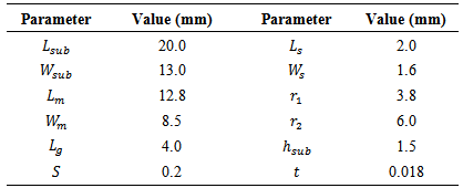
  is 13×20mm2. The proposed antenna with various design parameters is constructed and the numerical results of the proposed antenna, impedance bandwidth and radiation characteristics, are presented and discussed. The CST is used to optimize the antenna and HFSS is used to validate the results. Table 1 lists the optimized geometric parameters of the proposed antenna (Ant3). The impedance bandwidth performance for these antennas is shown in Fig. 3.
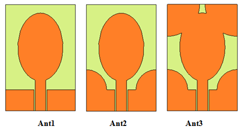 | Figure 1. Geometry of various antennas involved in the design evolution |
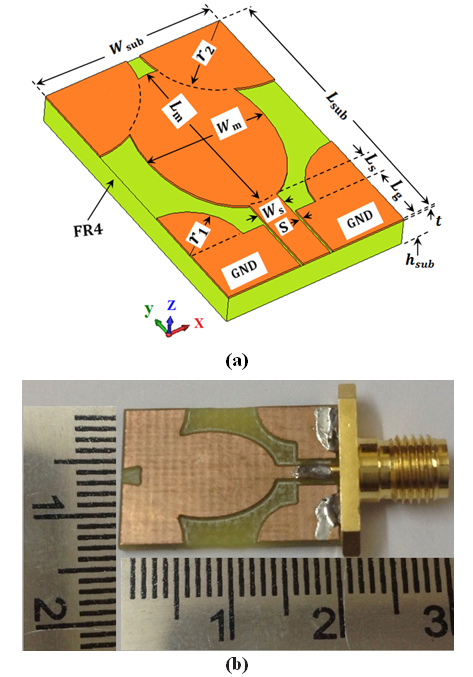 | Figure 2. (a) Configuration of the proposed antenna with its dimensions and parameters, (b) photograph of the fabricated monopole antenna |
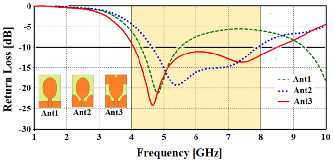 | Figure 3. CST simulated return loss curves of various antennas |
|
 ) is sensitively affected by using QCPL loaded structures while lower frequency (
 ) is less affected. In addition, it is seen from Fig. 3 that the three designed antennas have two resonant modes, the first one (
 ) and the second one (
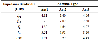
 ), which are sensitive to loading structures.Table 2 illustrates these two resonances beside to the lower and upper frequency,
  and
and  , respectively, and the operating band (BW =
  -
-  ) for the aforementioned three antennas. The following findings can be drawn from Table 2 and Fig. 3:i. One resonant-mode
  is generated from Ant1 whereas two resonant-modes
  and
and  were generated from Ant2 and Ant3. In addition, Ant3 has the lowest
  of
of  and the largest
  of
of  in comparing with other antennas. These two values are the nearest to the lower and upper frequency of C-band (4.0 and 8 GHz).ii. Antenna1 has the lowest bandwidth of 1.21 GHz and Ant3 has the largest bandwidth of 4.43 GHz while Ant2 has a bandwidth of 3.27 GHz.iii. Antenna1 operates in the band
  to
to  (4.30 GHz to 5.51 GHz), Ant2 in the band (4.64 GHz to 7.91 GHz), and Ant3 satisfies the C-band (4 GHz to 8 GHz) through operating from 4.07 GHz to 8.50 GHz.
|
4. Simulation and Measurement Results
- The proposed antenna has been constructed and analyzed by using CST MWS and HFSS softwares, and measured by using Anritsu 3650A-1 vector network analyzer. Figure 4 shows the simulated and measured return loss of the proposed antenna (Ant3) and good agreement between them is satisfied. Also, the measured return loss shown in Fig. 4 demonstrates that the antenna operates between 4.23 to 8.37 GHz for return loss less than -10 dB, which can cover the C-band frequency range. A slight difference between the two simulations is due to the two different numerical techniques employed by the two softwares. The measured results show a slight deviation in resonant frequencies, but follow the same pattern of simulated results. This can be due to the uncertainty in permittivity
 and thickness of the substrate and fabrication misalignments.
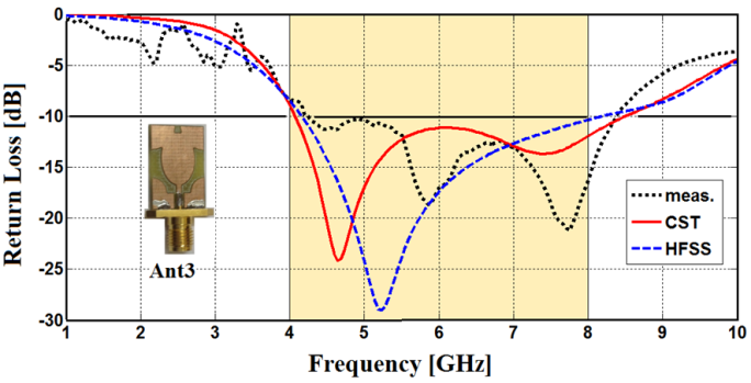 | Figure 4. Measured and simulated return loss of the planar monopole antenna |
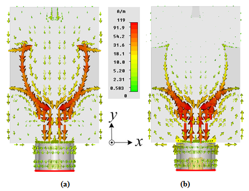 | Figure 5. Simulated results of the surface current distributions for proposed antenna at (a) 4.6 GHz and (b) 7.4 GHz |
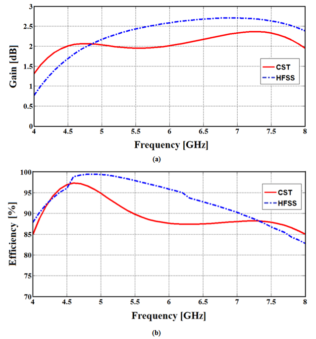 | Figure 6. CST and HFSS simulated results of (a) gain and (b) efficiency of the proposed antenna |
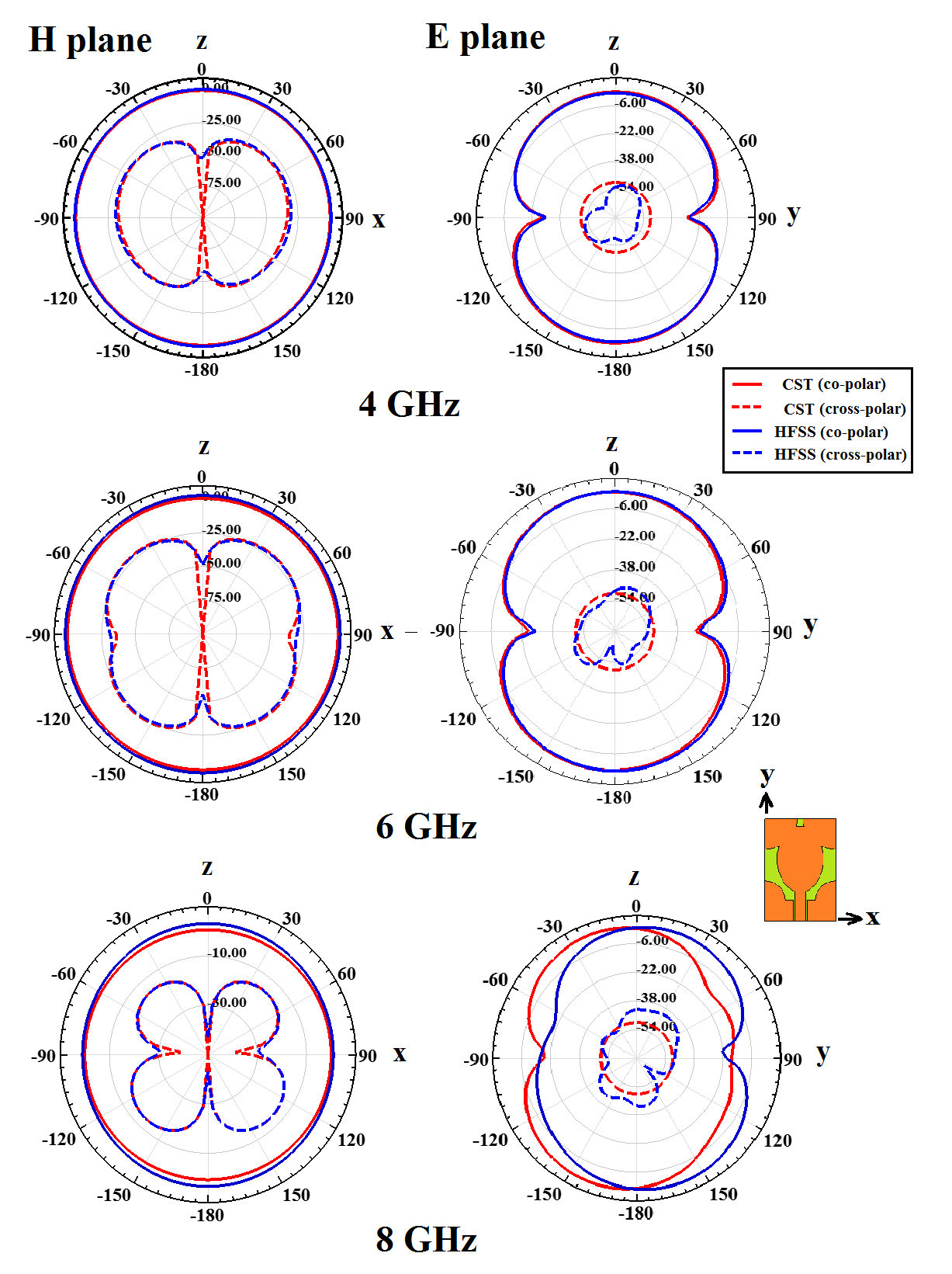 | Figure 7. CST and HFFSS Simulated directivity patterns in E plane (yz) and H plane (xz) for the proposed antenna at 4, 6, and 8 GHz |
5. The Detailed Analysis of Geometrical Parameters
- The influences of the related geometrical dimensions on the impedance bandwidth are further investigated. CST MWS simulations have been done to observe the variations of return loss with different
 , and
, and  , given in Figs. 8 and 9. The radii of QCPLs,
  and
and  and the elliptical-shaped major and minor axis
  and
and  are fixed as 3.8, 6.0, 12.8 and 8.5 mm, respectively, in the optimally designed antenna.
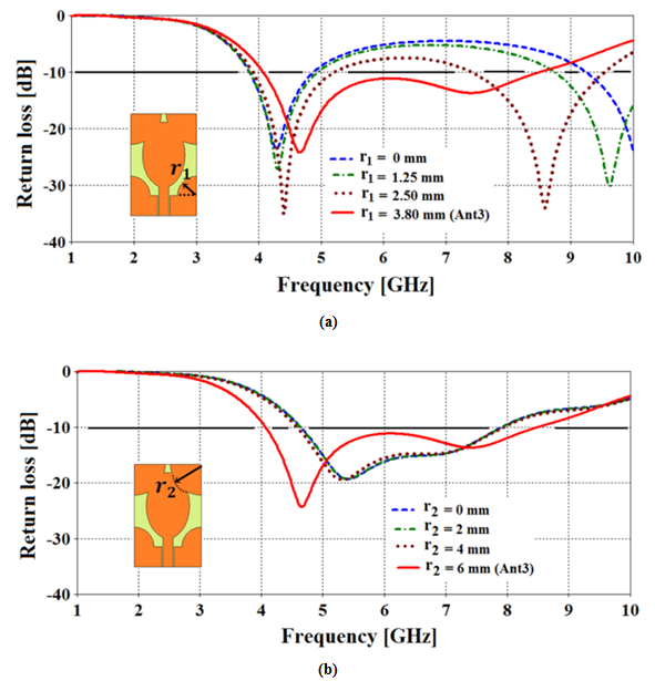 | Figure 8. Simulated return loss of the proposed antenna for various (a) r1 (b) r2 of QCPL radii., other parameters remain as in (Table 1) |
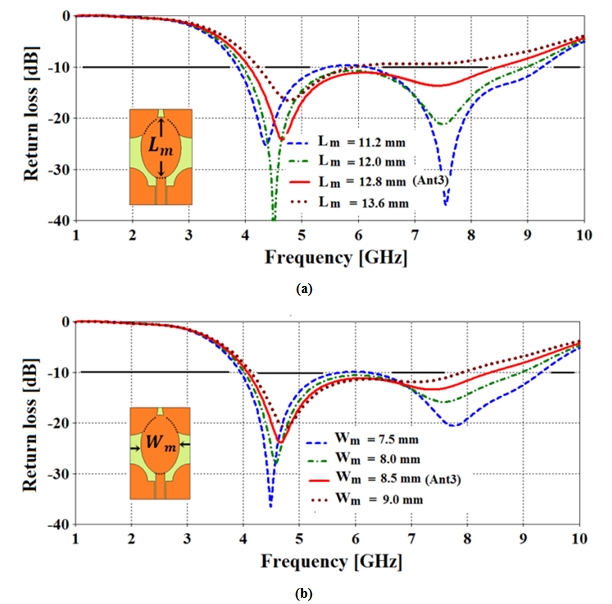 | Figure 9. Simulated return loss of the proposed antenna for various (a)  (b) (b)  of elliptical monopole major and minor axis,.other parameters remain as in (Table 1) of elliptical monopole major and minor axis,.other parameters remain as in (Table 1) |
 varying from zero to 3.8 mm. As shown when
  increases, the higher resonance mode of upper band is decreasing until an optimum value of 3.8 mm, the lower frequency of the upper band drifts toward upper frequency of the lower band and leads to constitute wider band. Thereby, a conclusion can be drawn that the radius of the ground-quarter circle loaded stub resonator
  plays a critical role in controlling the bandwidth enhancement of the proposed antenna. On the other hand, the radius of elliptical-stub resonator
  has less affect on impedance bandwidth than
  and as shown in Fig. 8(b), the lower frequency of the band is decreasing with increasing in
  . Thus, the two pairs of QCPL represent important parameters in broadband antenna design of the monopole antenna.In Fig. 9(a) and (b), the effect of the elliptical-shaped monopole structure parameters, major and minor axis,
  and
and  on antenna return loss are plotted via CST simulator. The
  and
and  simulation results show that the upper freuency is more affected than lower frequncy of the return loss impedance bandwidth. Thus, the above study is very vital for the designer to have information in achieving the desired operating wide band performance for various applications based on this antenna prototype.
6. Conclusions
- In this paper, a new compact planar antenna design for broadband operation is proposed. The resonator-loaded method, by using two pairs of quarter-circle parasitic load (QCPL) added to the upper corners of the monopole substrate and ground planes are presented for achieving a compact size and good broadband operation performance over the desired C-band. The antenna prototype has been designed, fabricated and tested. Measured results show reasonable agreements with simulated results (CST MWS and HFSS), validating our design concept. The proposed antenna features compact size, simple structure, good broadband operating bandwidth, and stable radiation patterns, indicating it can be a good candidate for WLAN 5.2/5.8 in the (5.15–5.35 GHz and 5.75–5.825 GHz) bands, WiMAX 5.5 in the (5.25–5.85 GHz) band, satellite radio, communications satellites, weather radar, etc.The work presented in this paper can be extended in the future to address the following issuesi. Apply the concept of parasitic element technique that adopted in this paper to radiator shapes other than elliptical geometry, for example, pentagon, hexagon or other geometrical configurations with different parasitic elements loaded to the antennas' monopole radiator.ii. Applying optimization algorithms such as particle swarm optimization, ant colony optimization or any other new optimization techniques to extent our presented work to deal with more goals such as antenna size miniaturization, antenna gain enhancement, and improvement in the axial ratio bandwidth of designed antenna for circular polarization application.
ACKNOWLEDGMENTS
- The author acknowledges gratefully the help provided by Ghaleb N. Radad and Mahmood R. Muhsen from the Ministry of Science and Technology (MOST), Iraq for their help in the fabrication and measurement of the prototype. The author would like to particularly thank Electronics Manufacturing Center, Industrial Development and Research of MOST for providing the fabrication and measurement facilities.