Mukesh Kumar1, Kanad Ray2
1SKIT, Jaipur, India
2ASET, Amity University, Rajasthan, India
Correspondence to: Kanad Ray, ASET, Amity University, Rajasthan, India.
| Email: |  |
Copyright © 2014 Scientific & Academic Publishing. All Rights Reserved.
Abstract
This paper presents the design and performance of a compact broadband circularly polarized CPW feed rectangular ring antenna. This antenna is simulated and fabricated on a glass epoxy FR4 substrate with a thickness of 1.6 mm and relative permittivity of 4.4 and loss tangent of .025. By introducing a square slot in the centre of the patch an impedance bandwidth nearly 10.3 GHz is achieved. The presented antenna has been designed, simulated and measured successfully. The simulation analysis of designed antenna is carried out using HFSS software and measurements are performed using Vector network analyzer. The obtained results with this antenna make it a suitable antenna for UWB systems and portable applications.
Keywords:
Square slot, Coplanar waveguide (CPW) feed, Axial ratio, Radiation patterns
Cite this paper: Mukesh Kumar, Kanad Ray, Design and Performance of a Compact Broadband Circularly Polarized Rectangular Ring Antenna, International Journal of Electromagnetics and Applications, Vol. 4 No. 2, 2014, pp. 49-55. doi: 10.5923/j.ijea.20140402.03.
1. Introduction
A conventional microstrip antenna exhibits inherent drawback of narrow impedance bandwidth, low gain and single operating frequency corresponding to its dominant mode [1-2]. Numerous techniques have been investigated and reported in recent past to enhance the impedance bandwidth of printed antenna [3]. There have been reports of insertion of various shapes of slots to enhance the impedance bandwidth of antennas which includes quarter-wavelength line slot resonator [4], asymmetrical CPW slot [5], circular slot [6] and fractal shaped slot [7]. However most of these reported antennas are either large in size or do not have sufficient bandwidth required for many practical applications particularly for ultra wide band applications. Several other techniques including application of thicker substrates [8, 9], application of parasitic elements near externally excited element [11], and excitation of patch element through an aperture coupling [12] are also reported for enhancing the impedance bandwidth of antennas. In most of these cases bandwidth improves but in general remains limited at the most up to 3 to 3.5 GHz. Since the release by the Federal Communications Commission (FCC) of a band from 3.1GHz to 10.6GHz for ultra wideband (UWB) wireless communications, UWB is rapidly advancing as a short-range high data rate wireless communication technology. With ultra wideband (UWB) technology information are transmitted by generating radio energy at specific time instants in the form of very short pulses therefore occupying very large bandwidth. UWB technology is widely employed in many applications such as indoor positioning, radar, medical imaging and target sensor data collection. For the implementation of UWB systems we have to develop a suitable antenna with extremely wide bandwidth of 7.5GHz, return loss which should be less than -10dB, omni-directional, low directivity with uniform gain and high radiation efficiency However for achieving further higher bandwidth from antenna for example required in UWB communication systems, these techniques in general are unsuitable. In this communication, design of compact CPW feed square ring patch antenna is proposed for bandwidth enhancement. This antenna resonates at two frequencies and provides nearly 10.3 GHz frequency covering almost entire frequency range desired for UWB communication systems.
2. Antenna Designs
Initially a rectangular ring patch antenna having patch dimensions outer patch dimension 14 mm x 14 mm and inner square slot with dimension 6mm x 6mm is considered with infinite ground plane. The centres of patch and slot coincide with each other as shown in figure 1. The performance of this antenna simulated using HFSS simulation software considering presence of glass epoxy FR4 substrate material with dielectric constant єr = 4.4 and loss tangent 0.025 between the patch and the ground plane. This antenna is excited by a 50Ω microstrip feed line (line width 3mm and line length 8mm) and feed through a SMA connector. The variation of return loss with frequency suggests that antenna resonates at frequency 10.2 GHz and provides excellent matching with feed line.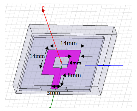 | Figure 1. The top view of the rectangular patch antenna with a slot |
In the above return loss graph shown in figure 2 we observe that this antenna resonant at 10.3 GHz having a band from 8.7 GHz to 11.1GHz but this band does not cover the range required for ultra wide band system. So iteration is required.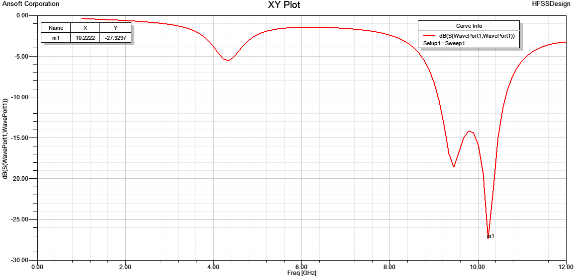 | Figure 2. Variation of the reflection coefficient (S11) with frequency of design shown in Fig.1 |
In the next step, shown in figure 3, keeping patch dimension and feed technique same as considered in previous case, the ground plane of antenna is modified by reducing its size in steps. In each step of modification, performance of antenna is optimized and finally the size of ground plane equal to 6mm x 30mm is selected. The performance of antenna simulated and it is realized that antenna resonates at 5.5 GHz frequency and provides impedance bandwidth from 1.4GHz to 8.1GHz as shown in figure 4 but still it is not sufficient for ultra wide band system because it is not covering the complete ultra wide band frequency range which is from 3.1GHz to 10.6GHz. So further iteration is required.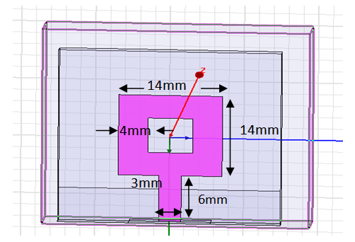 | Figure 3. The top view of the rectangular patch antenna with a slot |
Finally antenna is modified by replacing finite ground plane with coplanar waveguide (CPW) arrangement but the patch and feed line dimensions are retained as it is reported earlier. The antenna is again simulated with HFSS simulation software keeping dimensions of ground plane equal 6mm x30mm on both sides of feed line. The gap between feed line and considered ground plane is optimized and finally the gap w1 = .5 mm is selected. Finally selected antenna is designed using glass epoxy FR4 substrate material as shown in figure 5. This antenna is measured using vector network analyser.In the figure 5 software designed and fabricated antennas are shown.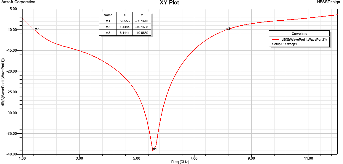 | Figure 4. Variation of the reflection coefficient (S11) with frequency of design shown in Fig.3 |
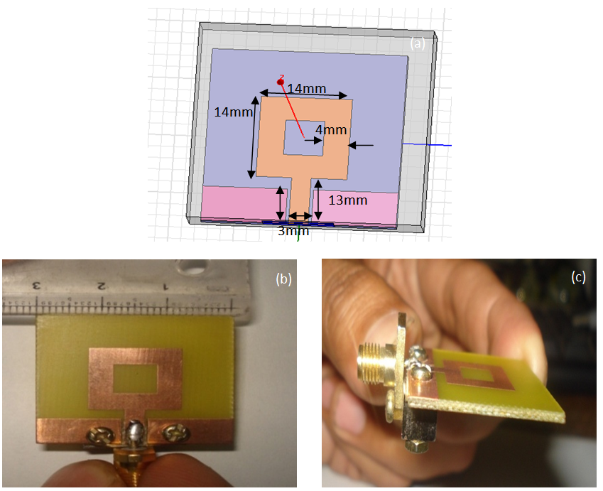 | Figure 5. (a) Rectangular patch antenna with cpw feed; (b) Top view of the fabricated antenna; (c) Side view of the fabricated antenna |
3. Results and Discussions
The variation of the reflection coefficient with frequency is shown in Fig. 6. From the figure we observe that the antenna resonant at two frequencies e.g. 5.10 GHz and 9.9 GHz and presents impedance bandwidth nearly 10.3 GHz or 159.6% with respect to the central frequency. The return loss in the entire bandwidth is below 10dB, which shows the perfect matching between the antenna and the transmission line. The measurements of reflection coefficient, VSWR were carried out with a vector network analyser. 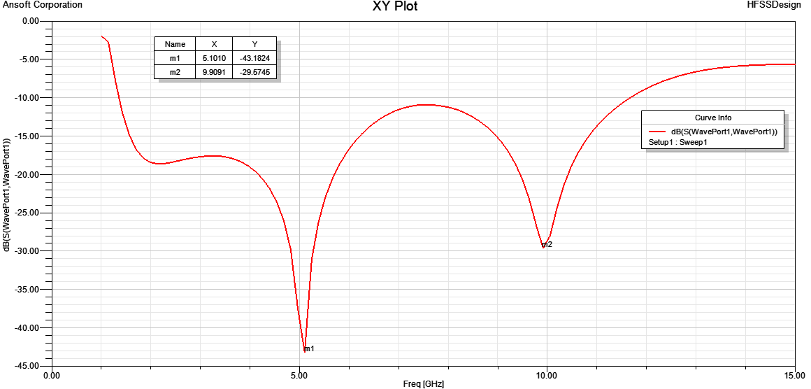 | Figure 6. The reflection coefficient v/s frequency graph is shown in figure |
The variation of measured reflection coefficient with frequency is shown in Fig.7. From this graph we observe that the measured result is close to the simulated result so we can use this antenna for practical purpose also.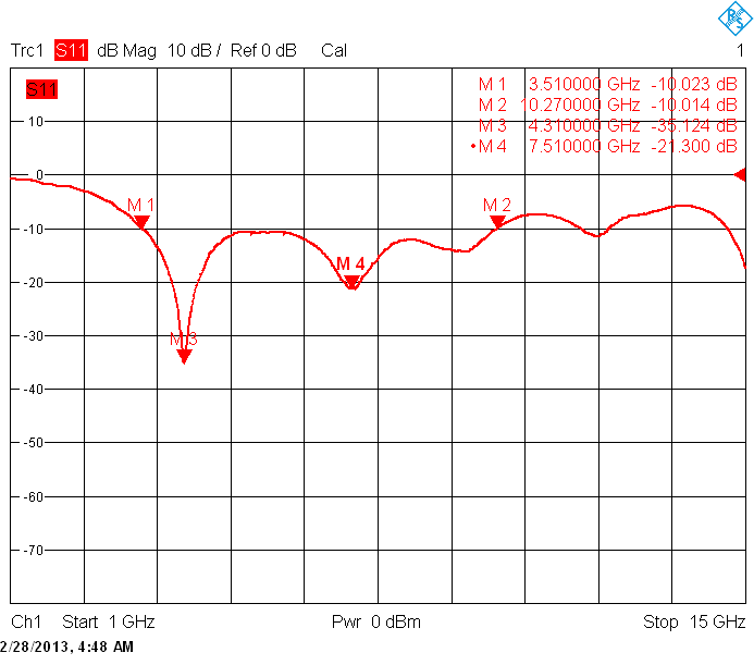 | Figure 7. The reflection coefficient v/s frequency graph |
The variation of the simulated and measured VSWR with frequency is shown in Fig. 8(a), (b). The value of the VSWR in both the cases is less than 2 which tell us about the perfect matching between the antenna and the transmission line.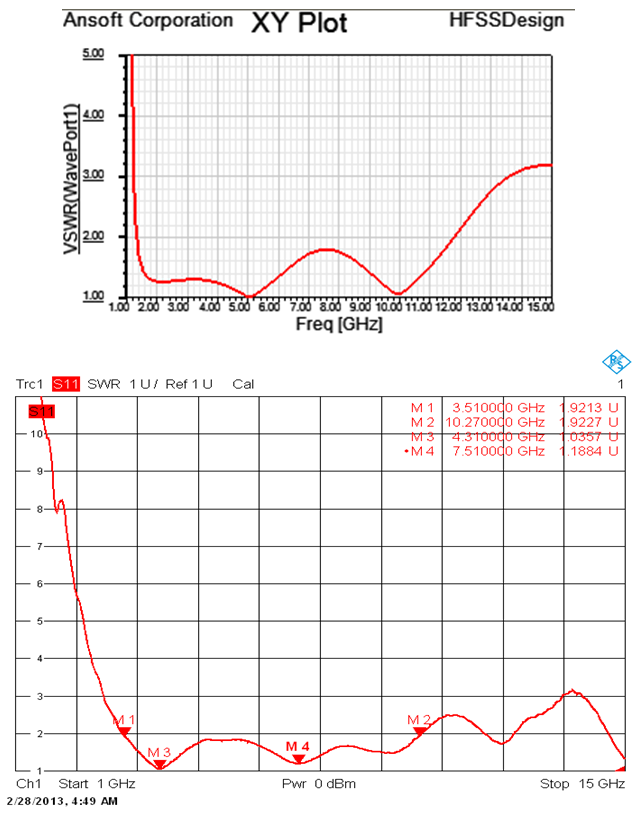 | Figure 8. (a) variation of the simulated VSWR with frequency; (b) variation of measured VSWR with frequency |
The variation of the simulated and measured value of smith chart is shown in Fig.9 (a), (b). From the smith chart we see it cross the real line at 1 which shows the perfect matching between the antenna and the transmission line.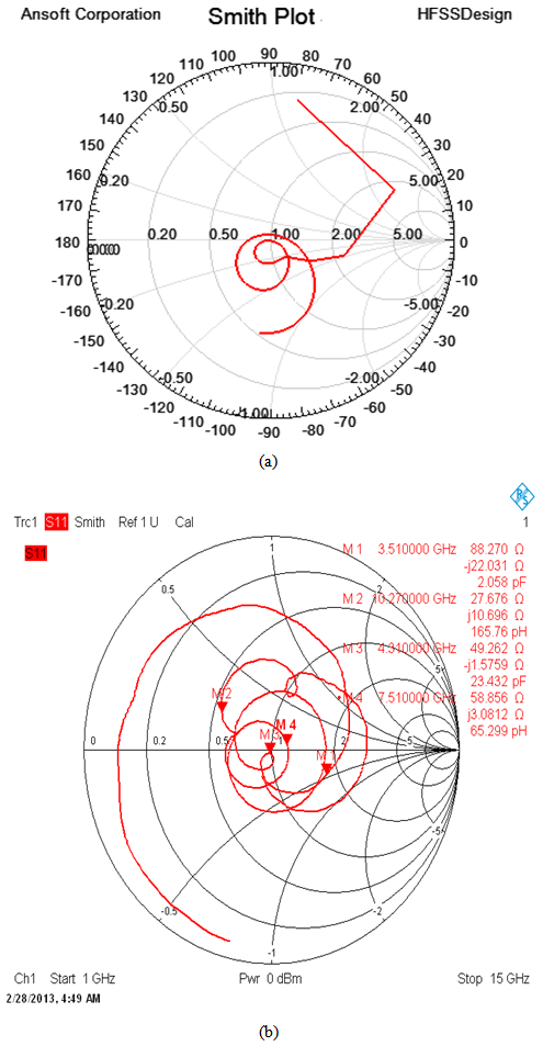 | Figure 9. (a) Variation of the simulated smith chart; (b) Variation of the simulated smith chart |
The radiation pattern of the proposed antenna at different frequencies is shown in the Fig. 10(a), (b), (c) given below. The pattern shows the omni directional behaviour of the proposed antenna. Omni directional pattern suggests us that this antenna can be used for broadcasting purpose.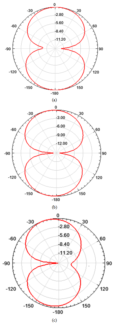 | Figure 10. (a) The radiation pattern at frequency 2.3GHz; (b) The radiation pattern at frequency 5GHz; (c) The radiation pattern at frequency 6.7GHz |
In the figure 11 the axial ratio with frequency is shown in figure which tells us that the proposed antenna is circularly polarized.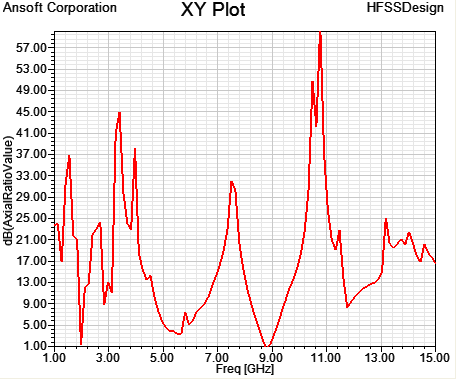 | Figure 11. The axial ratio with frequency |
The Antenna exhibits 10.3GHz bandwidth which is suitable for ultra wide band applications. The antenna is having good impedence matching i.e. maximum energy will be transferred.The Antenna is having omnidirectional radiation patterns means this antenna can be used for broadcast purpose.
4. Conclusions
Finally the designed antenna having a bandwidth of 10.3 GHz which covers complete ultra wide band. A novel compact circularly polarized antenna for ultra wide band applications has been presented and investigated. We found that by cutting a square in the centre of the patch with proper dimensions and with coplanar waveguide feed, large impedance bandwidth can be achieved in a very small size. Moreover the antenna is simple in its geometry and is fabricated using low cost glass epoxy substrate material. The radiation pattern of the antenna is omnidirectional so this antenna has applications in mobile and wireless network.Ultra wide range is from 3.1GHz to 10.6 GHz. There exists WLAN band which is from 5.15 GHz to 5.825GHz. This WLAN band Interfere with Ultrawide band range. To remove this band we have to use filters which stop this WLAN band. In future a new antenna can be designed which will work in the range 3.1 GHz to 5.15 GHz and 5.825GHZ to 10.6GHz so that no use of filters are required and cost of antenna can be reduced.
ACKNOWLEDGMENTS
The authors are thankful to Mr. Sanyog rawat for helping us using HFSS simulation software. Authors are also thankful to Dr. Deepak bhatnagar, Brajraj Sharma, Rukhsar Zafar at Rajasthan University for using Vector Network Analyser device to measure the antenna.
References
| [1] | Federal Communications Commission, Washington, DC, “FCC report and order on ultra wideband technology”, 2002. |
| [2] | Eng Gee Lim, Zhao Wang, Chi-Un Lei, Yuanzhe Wang, K.L. Man,” Ultra Wideband Antennas – Past and Present”, IAENG International Journal of Computer Science, 37:3, IJCS_37_3_12, August 2010. |
| [3] | Baskaran Kasi, Lee Chia Ping, Chandan Kumar Chakrabarty “A Compact Microstrip Antenna for Ultra Wideband Applications” European Journal of Scientific Research, ISSN 1450-216X Vol.67 No.1 (2011), pp. 45-51. |
| [4] | Zhu, L., R. Fu, and K.-L. Wu, “A novel broadband microstrip-fed wide slot antenna with double rejection zeros” IEEE Antennas and Wireless Propagation Letters, Vol. 2, 194-196, 2003. |
| [5] | Zhang, L., Y.-C. Jiao, K. Song, and F.-S.Zhang, “A novel broadband CPW-fed asymmetrical slot antenna, Microwave and Optical Technology Letters, Vol. 50, No. 11, 2817-2820, 2008. |
| [6] | Yeo, J. and D. Kim, “Harmonic suppression characteristic of a CPW-FED circular slot antenna using single slot on a ground conductor," Progress In Electromagnetics Research Letters, Vol. 11, 11-19, 2009. |
| [7] | Chen, W.-L., G.-M. Wang, and C.-X. Zhang, “Bandwidth enhancement of a microstrip-line-fed printed wide-slot antenna with a fractal-shaped slot” IEEE Transactions on Antennas and Propagation, Vol. 57, No. 7, 2176-2179, 2009. |
| [8] | Guo, Y. X., K. M. Luk, K. F. Lee, and Y. L. Chow, “Double U-slot rectangular patch antenna” Electron. Lett., Vol. 34, 1805-1806,1998. |
| [9] | Yang, F., X.-X. Zhang, X. Ye, and Y. Rahmat-Samii, “Wide-band E shaped patch antennas for wireless communications” IEEE Trans. on Antennas and Propag., Vol. 49, 1094-1100, Jul. 2001. |
| [10] | Kumar, G. and K. C. Gupta, “Directly coupled multiple resonator wide-band microstrip antenna” IEEE Trans. on Antennas and Propag., Vol. 33, 588-593, Jun. 1985. |
| [11] | Wi, S. H., Y. S. Lee, and J. G. Yook, “Wideband microstrip patch antenna with U-shaped parasitic elements” IEEE Trans.on Antennas and Propag., Vol. 55, No. 4, Apr. 2007. |
| [12] | Vera, G. A., A. Georgiadis, A. Collado, and S. Via,” Design of a 2.45 GHz rectenna for electromagnetic (EM) energy scavenging”, IEEE Radio and Wireless Symposium, 61-64, Mar. 2010. |
 Abstract
 Reference
 Full-Text PDF
 Full-text HTML