Asmaa H. Majeed1, Abdulkareem S. Abdullah1, Raed A. Abd-Alhameed2, Khalil H. Sayidmarie3
1Department of Electrical Engineering, College of Engineering, University of Basrah, Basrah, Iraq
2School of Engineering, Design and Technology, University of Bradford, UK
3Dept. of Communication Eng., College of Electronic Eng., University of Mosul, Mosul, Iraq
Correspondence to: Khalil H. Sayidmarie, Dept. of Communication Eng., College of Electronic Eng., University of Mosul, Mosul, Iraq.
| Email: |  |
Copyright © 2014 Scientific & Academic Publishing. All Rights Reserved.
Abstract
The present work investigates the operation performance of 2-element configuration multiple input Multiple Output (MIMO) antennas system using Cylindrical Dielectric Resonator (CDR). The MIMO antenna arrays achieve 22.2% impedance bandwidth at S11 ≤ -10 covering the bandwidth from 10GHz to 12.5GHz that meets the essential requirements of wide band communications applications. The first array gives a maximum isolation of 27dB at an element spacing of 22mm, whereas the second array presents a maximum isolation of 42.55dB at element spacing of 12.25mm.
Keywords:
DRA, MIMO antennas, Mutual coupling
Cite this paper: Asmaa H. Majeed, Abdulkareem S. Abdullah, Raed A. Abd-Alhameed, Khalil H. Sayidmarie, MIMO Antenna Array Using Cylindrical Dielectric Resonator for Wide Band Communications Applications, International Journal of Electromagnetics and Applications, Vol. 4 No. 2, 2014, pp. 40-48. doi: 10.5923/j.ijea.20140402.02.
1. Introduction
Multiple Input Multiple Output (MIMO) technology plays an important role for most of the advanced wireless communication systems to achieve high data rates and full diversity. A significant increase in channel capacity could be achieved without the need of additional bandwidth or more transmitted power by deploying such MIMO system. In turn, this could also improve the array gain and space diversity, thereby improving the spectral efficiency and reliability. However, when the antennas are closely placed, the couplings between the electromagnetic waves of different antennas interfere strongly and could degrade the antenna performance that results in low Signal to Noise Ratio (SNR). The amount of reduction of such coupling between the elements of the array is the main objective of MIMO systems [1]. The dielectric resonator antenna (DRA) is considered to be a viable and feasible solution to the conventional conductor antennas at millimeter wave frequencies with its low loss especially compared to the microstrip patch antenna. Moreover, its bandwidth has been recently improving and it is being competing with those obtainable from the microstrip antennas. [2-5].In many cases as with a single element DRA, desired specifications cannot be achieved; for example high gain, high efficiency, directional radiation pattern cannot be synthesized with a single DRA of any shape. In these applications, a DRA array with an appropriate number of elements arrangement and a modified feed configurations can be used to provide desired specifications [6].Aperture coupled DRAs are more feasible with array designs since the feed network might be placed on the back side of the antenna that reduces the unwanted coupling between the feed line and radiating elements. This type of arrangement may support to have the feed network and antennas on the same side. Aperture coupling will add a good value when the designed array size is larger [7]. The Mutual Coupling between elements in arrays employing DRAs has previously been studied in the literature [8-9]. A comprehensive study on the mutual coupling between a pair of cylindrical DRAs for different radius to height ratios (a/h) had been presented in [9]. The results proved that the isolation increases as the ratio of (r/h) increases. The mutual coupling between a pair of hemispherical DRAs has been discussed in [10]. The study has proved that the mutual coupling is significant and thus should be considered when designing an array of H-DRAs.For the present work, two MIMO array antenna designs using two cylindrical DRA's are proposed. In the first, two parallel elements CDR array is considered by using two identical CDRA antenna elements fed simultaneously through two independent microstrip lines. The second design is an array of two orthogonal array elements configuration of CDRA. The 2-element array is treated as a two-port network. The theoretical model analysis is carried out using CST Microwave Studio [11] which is based on finite integration technique (FIT).
2. MIMO Array Antenna Design
In this section, the design for single DRA element is presented, and then two arrays incorporating two DRA elements are proposed and investigated for operation as MIMO antenna arrays.
2.1. Single DRA Antenna Design
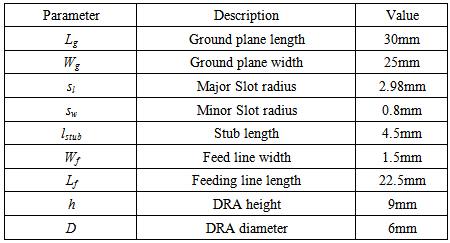
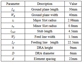
In the beginning a CDRA antenna fed by an elliptical slot, shown in Figure 1, is designed and optimized in terms of its dimensions parameters, and the optimized parameters are shown in Table 1. The realized reflection coefficient and gain of the elliptical slot CDRA antenna are shown in Figures 2 and 3 respectively. The antenna achieves a 23% at return loss ≤ -10dB bandwidth extending from 9.97 GHz to 12.558GHz, and gain ranging from 5.5 to 7.25dBi. The performance of this antenna shows that it is suitable for use as a 22 MIMO array as explained in the following sections.Table 1. Detailed parameters of the proposed antenna
 |
| |
|
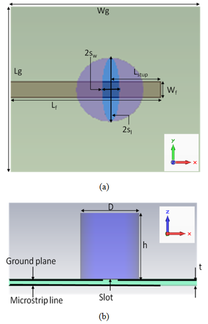 | Figure 1. Elliptical slot cylindrical shape DRA (a) Top view and (b) Side view with design parameters |
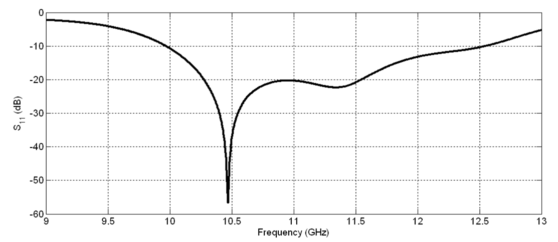 | Figure 2. Calculated reflection coefficient versus frequency for the proposed DR antenna |
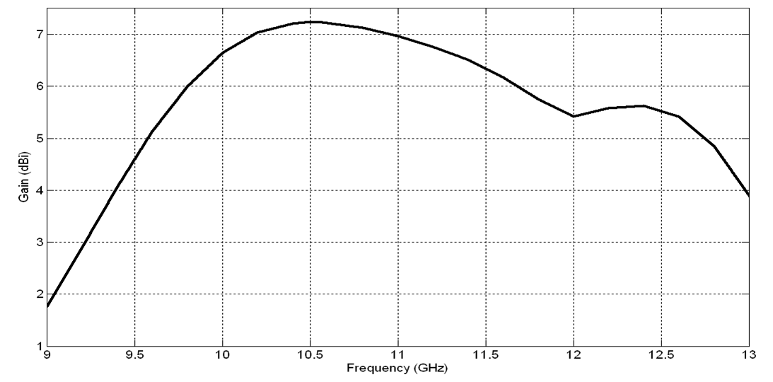 | Figure 3. Realized gain versus frequency for the proposed DR antenna |
2.2. The Two Parallel –Elements DRA Array
The DR antenna designed in the previous section is used here to form a two-element MIMO array as shown in Figure 4. This antenna is designed on the basis of using spatial diversity in which the same data is transmitted over each of the multiple paths. In this case, each of the two elements is essentially transmitting and receiving the same data although the data is coded differentially.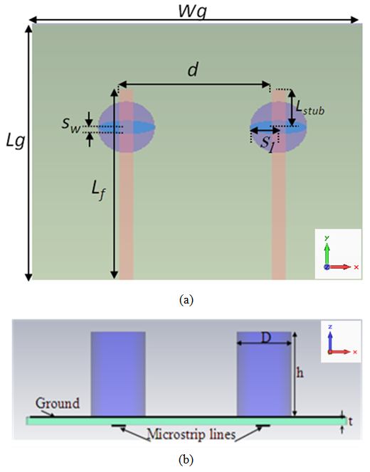 | Figure 4. The two parallel-element MIMO array using CDR's antenna (a) Top view and (b) Side view with design dimensions and parameters |
Mutual Coupling is an important factor that should be considered while designing an array. Mutual coupling can affect the performance of the array like radiation patterns, resonance frequency and bandwidth. So it is necessary to place the elements in such a way that helps to reduce mutual coupling effects. The spacing between two antenna elements mainly affects the mutual coupling between elements. In this design, the two aperture-coupled cylindrical DR elements are placed in parallel. The level of mutual coupling not only depends on the spacing between the elements but also on the structure dimensions, dielectric constant of the DRA and mode of the operation.The simulated reflection coefficient |S11| (|S11|=|S22|) versus frequency results of the parallel two-element array for various element spacing are shown in Figure 5. In this set of simulations, the substrate width Wg was chosen as 40mm. The results show that for an element-spacing d ranging between 13mm and 25mm the bandwidth is marginally affected while better matching is achieved for the spacing of 22mm. 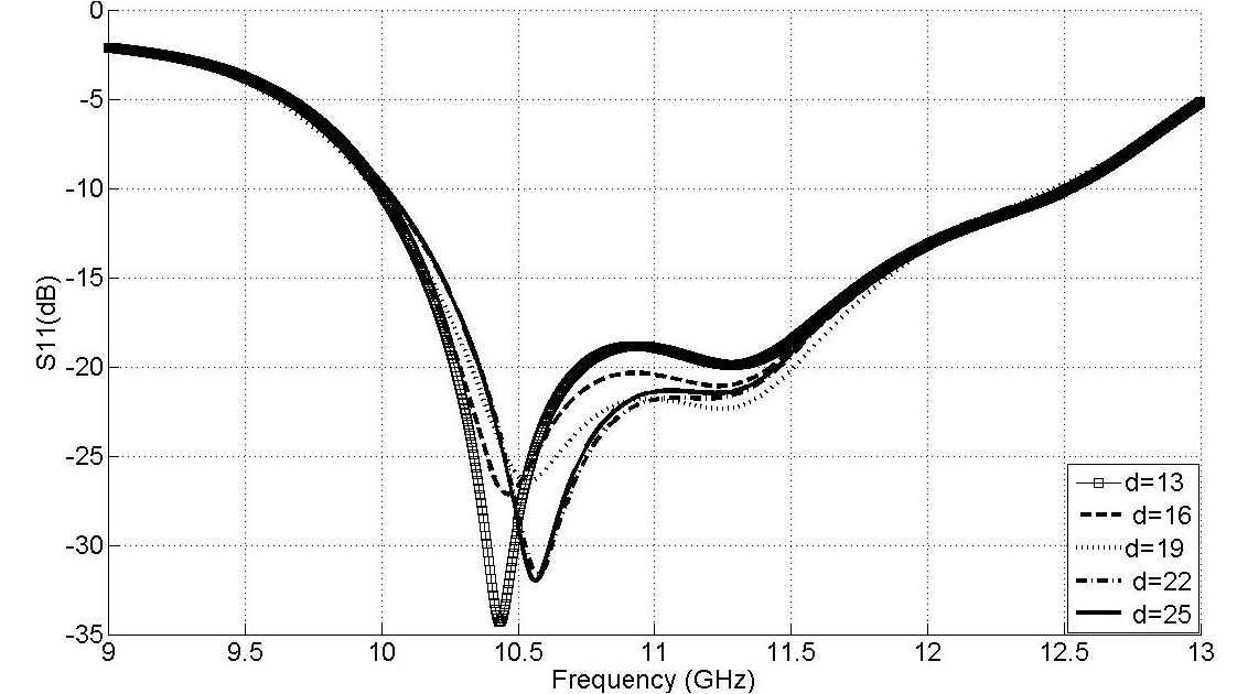 | Figure 5. Simulated reflection coefficient |S11| results versus frequency for the two parallel-element array for various spacing d |
The simulated mutual coupling |S12| (as the network is passive then |S12|=|S21|) versus frequency for various elements spacing values is shown in Figure 6. It is clear from figure that there are dramatic changes at lower frequencies.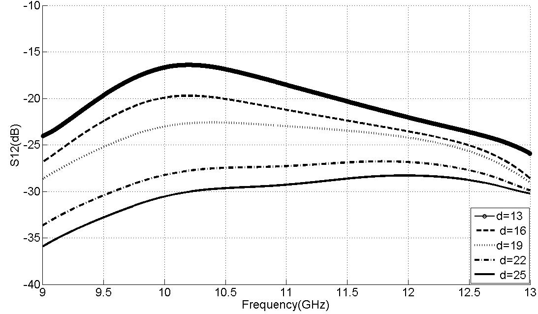 | Figure 6. Simulated coupling coefficient |S12| results versus frequency for the two parallel-element array for various spacing d |
The correlation coefficient ρe between the two antenna elements has also been calculated from the achieved S-parameters using the following formula [12]: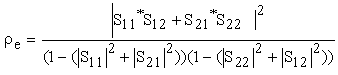 | (1) |
Figure 7 shows the calculated correlation coefficient ρe variations with frequency when element spacing values d of 13, 16, 19, 22, and 25 mm were used. It is clear that the correlation between antenna elements changes with frequency considerably. Moreover, many deep nulls can be observed. In general, the trend of variation shows that larger spacing results in better isolation.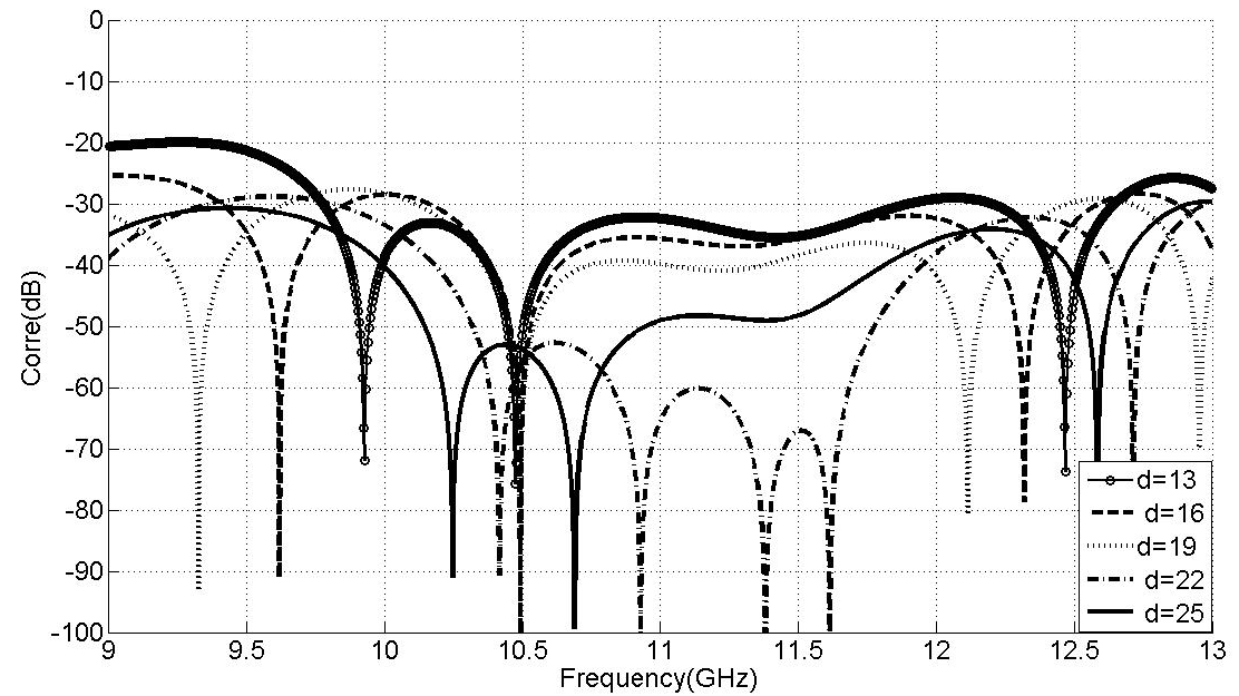 | Figure 7. Correlation coefficient ρe versus frequency at different element spacing values |
Based upon the above results, a value 22mm was chosen for element separation “d”, and the antenna parameters were then optimized to the values shown in Table 2. Table 2. Detailed parameters of the proposed two parallel-element antenna
 |
| |
|
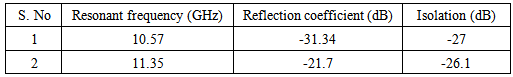
Figure 8 shows the simulated results of reflection coefficient and mutual coupling of parallel-element MIMO array using proposed DR antenna. The proposed antenna resonates at dual frequencies of 10.57 GHz and 11.35 GHz with an impedance bandwidth of 22.22% (10 GHz to 12.5 GHz). The two-element MIMO array gives a flat isolation of better than 27 dB that is reasonable for a separation of 22 mm (0.825λo at the center frequency of 11.25 GHz) between the two elements of the antenna array. Table 3 lists the results obtained from the proposed antenna array.Table 3. Results obtained for the proposed two parallel-element MIMO antenna shown in Figure 4
 |
| |
|
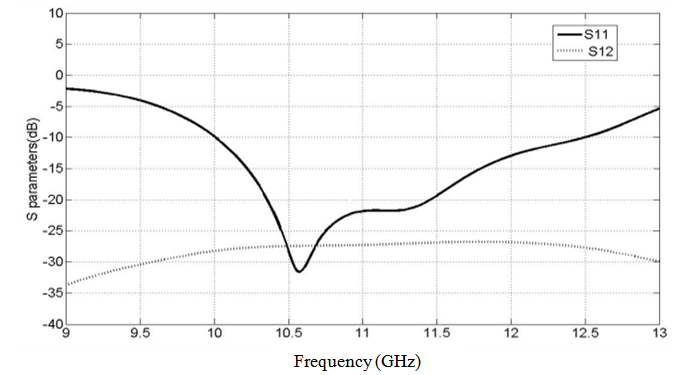 | Figure 8. S parameters of the proposed two parallel-element MIMO array |
Simulated realized gain of the antenna array is shown in Figure 9. From this figure, it can be observed that the gain at the resonant frequencies is more than 8 dBi which is sufficient for many wireless applications.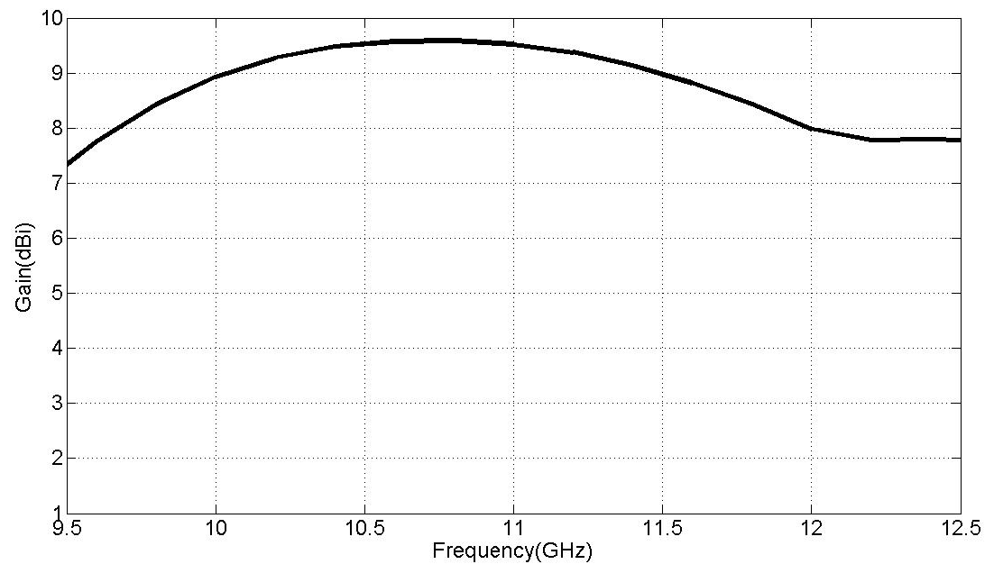 | Figure 9. Simulated gain of the proposed two parallel-element MIMO array |
Figure 10 shows the computed radiation patterns of the proposed antenna at 10.57GHz and 11.35GHz. Broadside radiation patterns are observed with the co-polarized fields generally stronger than the cross polarized fields by 20dB in the boresight direction. 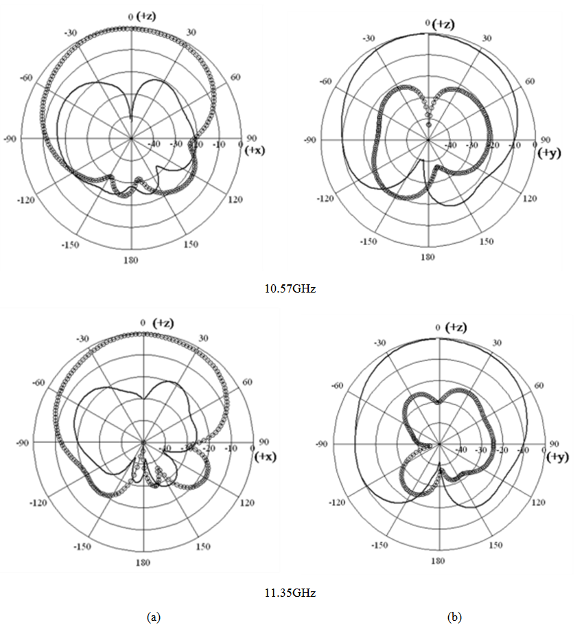 | Figure 10. Radiation patterns of the two parallel-element proposed antenna (a) xz-plane and (b) yz-plane; Eθ (solid) and E (solid -circles) |
The distance of the horizontal antenna from the upper edge of the substrate is y=11.4mm. The results of the parametric study to show the effect of the element spacing d on |S11| and |S22| are shown in Fig. 12 and Fig. 13 respectively. It is seen from Fig. 12 that increasing the element spacing does not have much effect on bandwidth, but it can give better matching for antenna 1. Figure 13 shows that increasing the element spacing results in some increase in bandwidth, as well as better matching for antenna-2. The reason for not obtaining similar results for both antennas can be attributed to the fact that the effect of the edge of the substrate is not similar for the two antennas.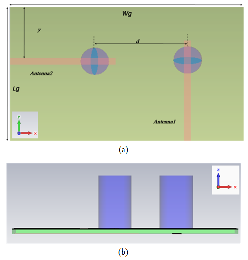 | Figure 11. The two orthogonal-element MIMO array using CDR's antenna (a) Top view and (b) Side view with design dimensions and parameters |
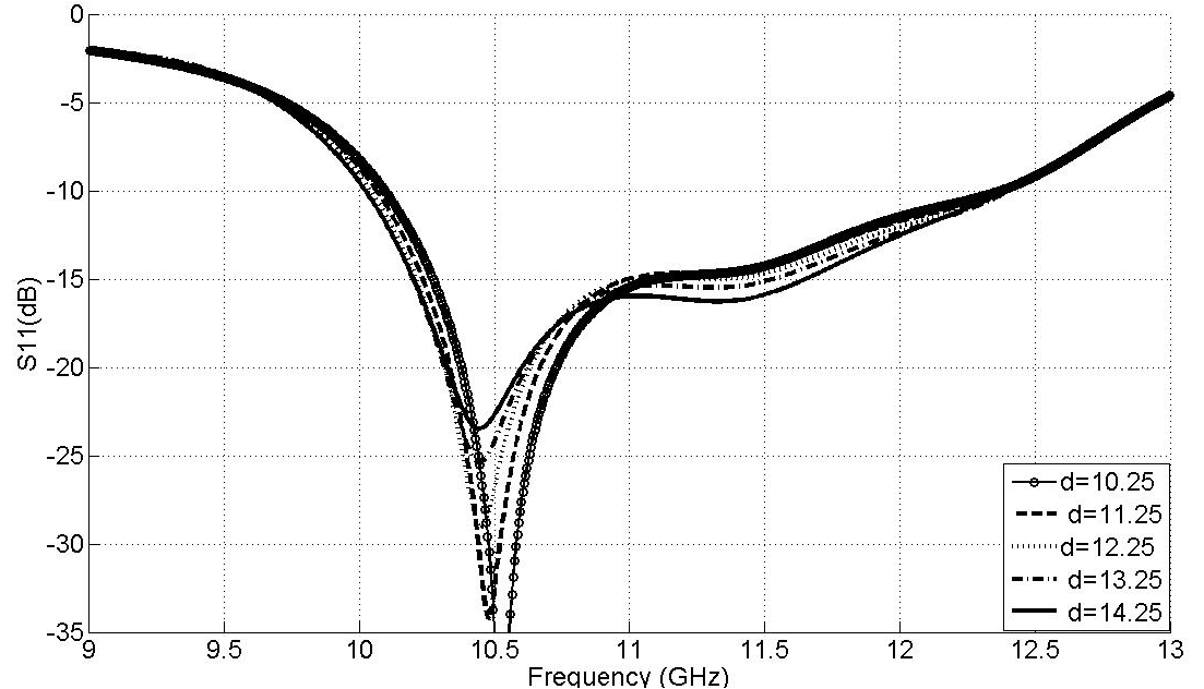 | Figure 12. Simulated |S11| results versus frequency of two orthogonal-element array for different spacing d |
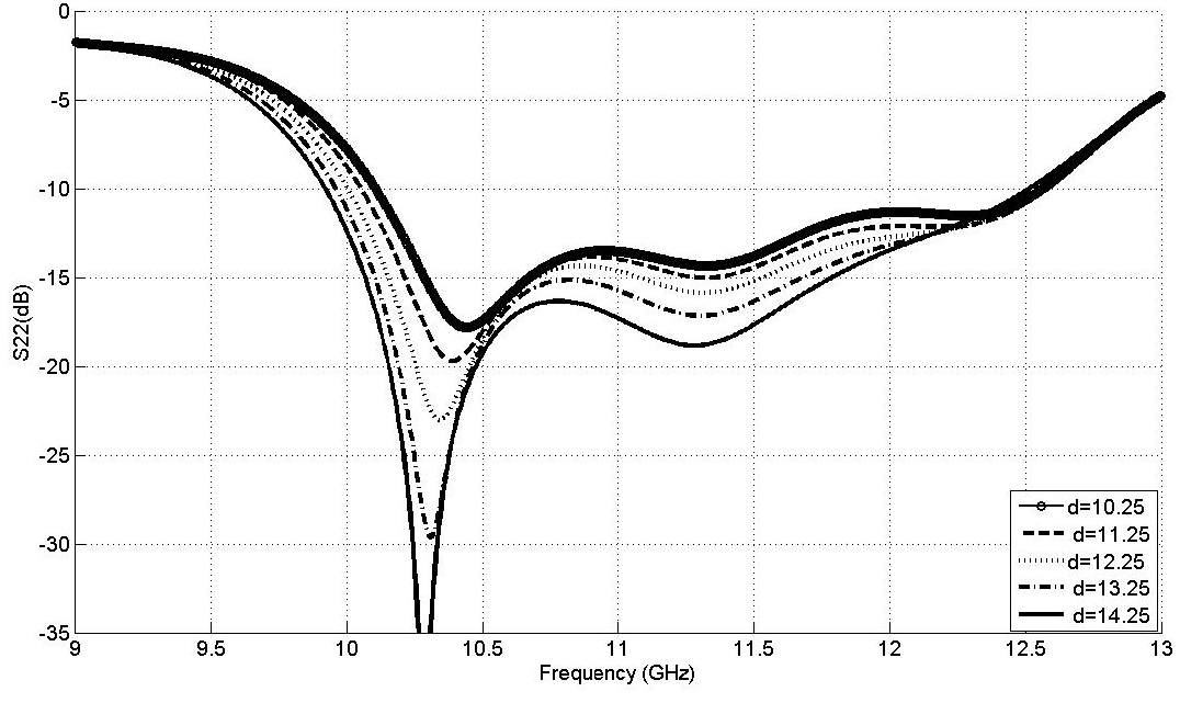 | Figure 13. Simulated |S22| results versus frequency of two orthogonal-element array for different spacing d |
The other S-parameters |S12| and |S21| are also studied and obtained results are presented in Figure 14 and Figure 15 respectively. It is clear from both Figures that as the spacing between the elements is increased, the mutual coupling decreases in general. However, this trend is reversed around frequency of 12.5GHz. The best found spacing is 12.25mm with a best isolation of 42.57dB at 12.35GHz for the total band from 10GHz to 12.5GHz.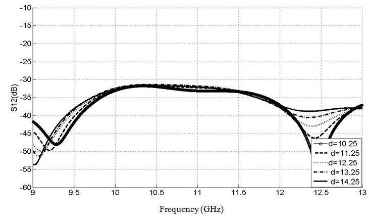 | Figure 14. Simulated |S12| results versus frequency of two orthogonal-element array for different spacing d |
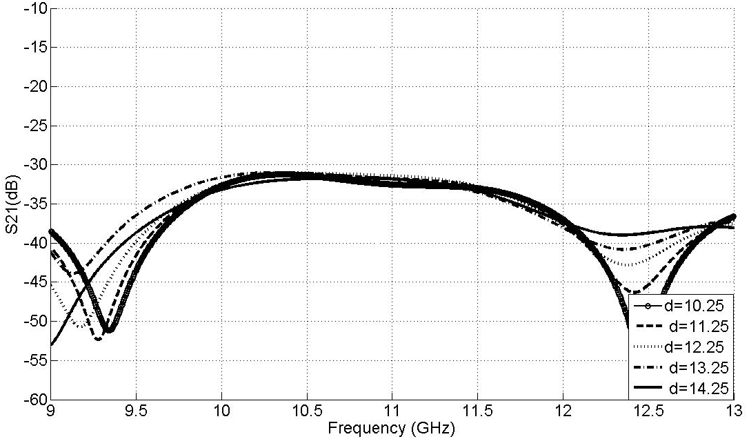 | Figure 15. Simulated |S21| results versus frequency of two orthogonal-element array for different spacing d |
Figure 16 shows the variations of the calculated correlation coefficient ρe with frequency at different element spacing values of d = 10.25mm, 11.25mm, 12.25mm, 13.25mm, and 14.25mm. In general larger spacing leads to better correlation coefficient performance.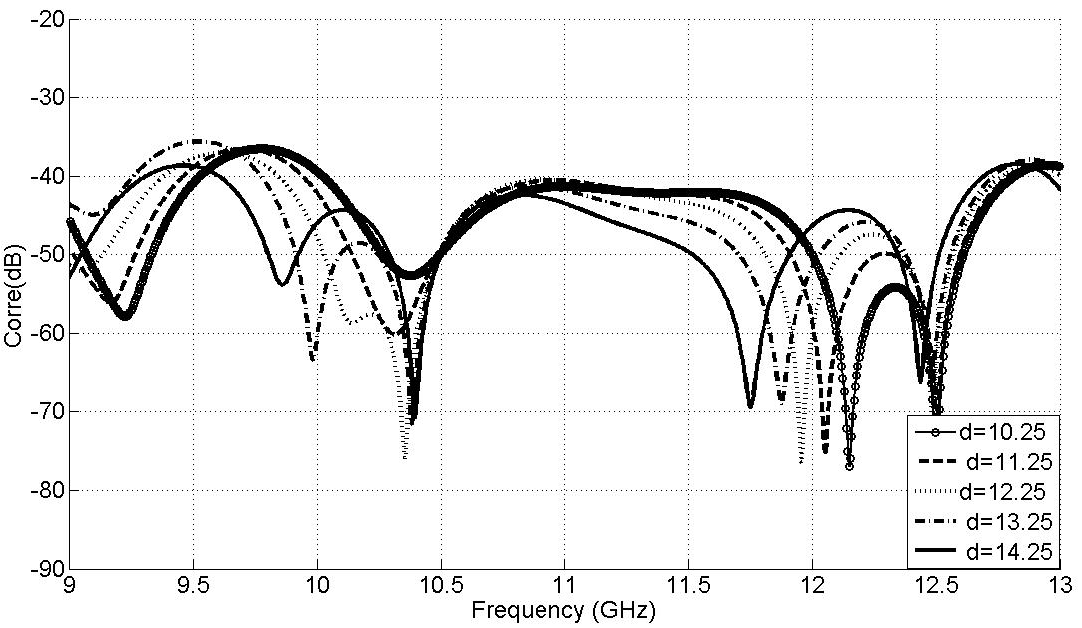 | Figure 16. Correlation coefficient versus frequency at various spacing values for the two orthogonal-element array |
The dimensions of the proposed orthogonal-elements array after optimization of its element spacing are listed in Table 4.Table 4. Detailed parameters of the proposed two orthogonal-element DRA array antenna
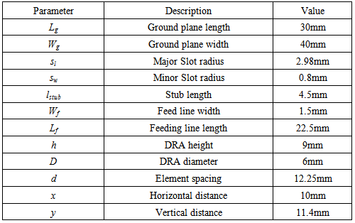 |
| |
|
Figure 17 shows the simulated results of reflection coefficient and mutual coupling of the orthogonal-element MIMO array in dB. The proposed antenna presents an impedance bandwidth of 22.22% (10 GHz to 12.5 GHz) and maximum isolation of 42.55 dB at 12.375 GHz.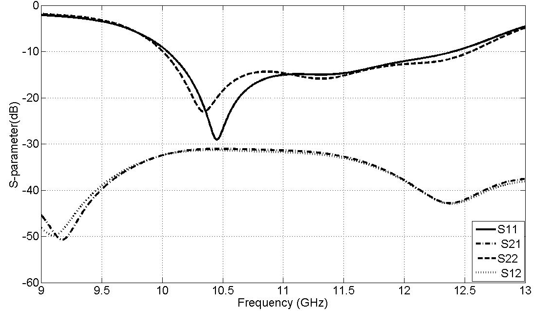 | Figure 17. S parameters of the optimized two orthogonal-element MIMO array |
Figure 18 shows the computed radiation patterns of the proposed antenna at 10.4GHz and 11.4GHz. From these figures a broadside radiation patterns are observed. In the XZ-plane, the cross-polar radiations are lower by about 20dB in the broadside direction.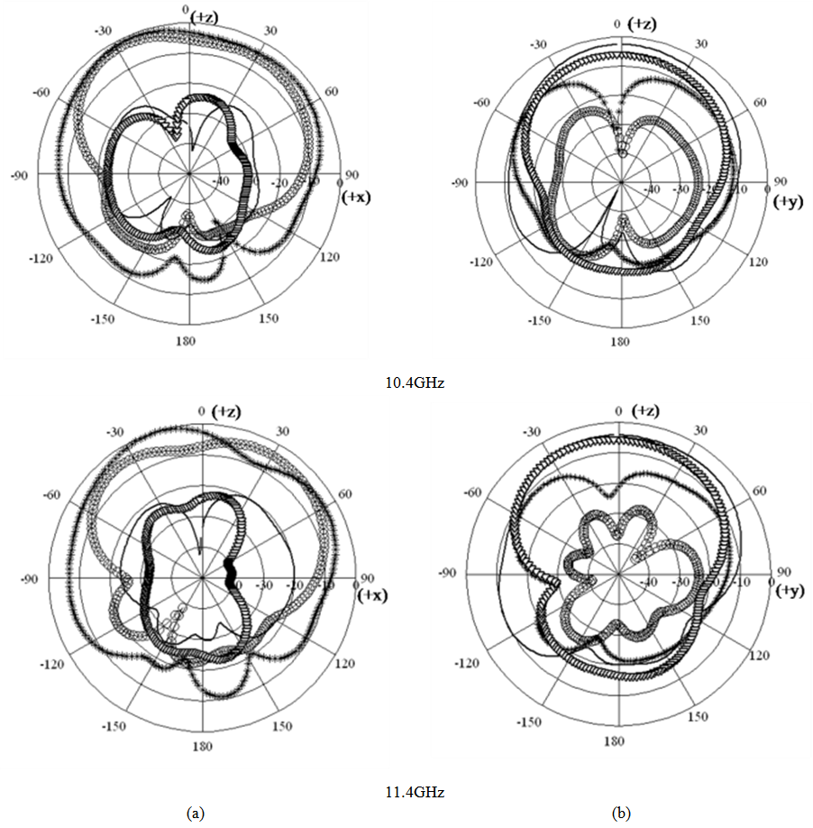 | Figure 18. Radiation patterns of the proposed two orthogonal-element antenna (a) xz-plane and (b) yz-plane; Eθ ant.1 (solid), E ant.1 (solid-circles), Eθ ant.2 (solid - *) and E ant.2 (triangles) |
3. Conclusions
In the present work, two designs for MIMO array using CDRA operating in the frequency range 10GHz to 12.5GHz has been presented for an impedance bandwidth of 22.22%. The proposed MIMO antennas showed higher isolation as recommended. The second antenna array offered quite spatial and polarization diversities by orienting the radiating elements orthogonally and separating them by minimum distance. Bandwidth improvement was achieved for both arrays when the mutual coupling is strong enough, or element spacing is small. It is concluded that, for a total bandwidth extending from 10GHz to 12.5 GHz and at a spacing 22mm the first array gave a best isolation of 27dB, and 42.55dB for the second array.
References
| [1] | A.A Abouda. and S.G.H. gagman, “Effect of Mutual Coupling on Capacity of MIMO Wireless Channels in High SNR Scenario” , Progress in Electromagnetic Research, PIER, 65 , pp.27-40, 2006. |
| [2] | A. Sharma and S. C. Shrivastava, “Bandwidth Enhancement Techniques of Dielectric Resonator Antenna" , International Journal of Engineering Science and Technology, Vol. 3, pp.5995-5999, 2011. |
| [3] | M. I. Sulaiman, and S. K. Khamas, “A Singly Fed Rectangular Dielectric Resonator Antenna With A Wideband Circular Polarization”, IEEE Antennas And Wireless Propagation Letters, vol. 9, pp. 615-618, 2010. |
| [4] | K. K. Gebril, S. K. A. Rahim, and A. Y. Abdulrahman, "Bandwidth Enhancement And Miniaturization of Dielectric Resonator Antenna for 5.8GHz WLAN", Progress In Electro magnetics Research C, Vol. 19, PP. 179-189, 2011. |
| [5] | A.H. Majeed, A.S. Abdullah, F. Elmegri, K.H. Sayidmarie, R.A. Abd-Alhameed and J.M. Noras, "Aperture-Coupled Asymmetric Dielectric Resonators Antenna for Wideband Applications", IEEE Antennas And Wireless Propagation Letters, Vol. 13, PP. 927-930, 2014. |
| [6] | M.S.M. Aras, M.K.A. Rahim, Z.Rasin and M.Z.A. Abdul Aziz, “An Array of Dielectric Resonator Antenna for Wireless Application”, IEEE International RF and Microwave Conference Proceedings, pp. 459.463, Dec 2008. |
| [7] | M. Brar and S. K. Sharma, “A Wideband Aperture-Coupled Pentagon Shape Dielectric Resonator Antenna (DRA) for Wireless Communication Applications”, IEEE International Symposium on Antennas & Propagation, 3-8 July 2011, pp.1674-1677. |
| [8] | K Jagadeesh Babu, K. Sri Ramakrishna and L. Pratap Reddy, “Reduction of Mutual Coupling in a MIMO Array Employing Circular DRAs”, International Journal of Information and Telecommunication Technology, vol. 4, PP. 12–15, 2012. |
| [9] | R. Chair, A. A. Kishk, and K.-F. Lee, “Comparative Study on the Mutual Coupling Between Different Sized Cylindrical Dielectric Resonators Antennas and Circular Microstrip Patch Antennas”, IEEE Transactions on Antennas and Propagation, Vol. 53, No. 3, pp. 1011–1019, Mar. 2005. |
| [10] | L. Kwai-Man, L. Wai-Kee, and L. Kwok-Wa, “Mutual Impedance of Hemispherical Dielectric Resonator Antennas”, IEEE Transactions on Antennas and Propagation, Vol. 42, pp.1652–1654,1994. |
| [11] | CST Microwave Studio, ver. 2011, Computer Simulation Technology, Framingham, MA, 2011. |
| [12] | S. Blanch, J. Romeu and I. Corbella, “Exact Representation of Antenna System Diversity Performance From Input Parameter Description”, Electronic Letters, Vol.39, pp. 705-707, 2003. |
 Abstract
 Reference
 Full-Text PDF
 Full-text HTML