-
Paper Information
- Next Paper
- Paper Submission
-
Journal Information
- About This Journal
- Editorial Board
- Current Issue
- Archive
- Author Guidelines
- Contact Us
International Journal of Electromagnetics and Applications
p-ISSN: 2168-5037 e-ISSN: 2168-5045
2014; 4(2): 31-39
doi:10.5923/j.ijea.20140402.01
Modeling of Dual-Band Crescent-Shape Monopole Antenna for WLAN Applications
 Abstract
 Reference
 Full-Text PDF
 Full-text HTML
Khalil H. Sayidmarie1, Likaa S. Yahya2
1College of Electronic Engineering, University of Mosul, Iraq
2Department of Electronic Techniques, Institute of Technology, Mosul, Iraq
Correspondence to: Khalil H. Sayidmarie, College of Electronic Engineering, University of Mosul, Iraq.
| Email: |  |
Copyright © 2014 Scientific & Academic Publishing. All Rights Reserved.
Modeling of dual-band monopole antennas is investigated. A recently presented dual band crescent-shape monopole antenna for WLAN applications is modeled by an RLC equivalent circuit using two methods. In the first method, the input impedance is represented by the first Foster canonical form. The equivalent circuit parameters at resonance are extracted from either the input impedance or the reflection coefficient responses of the simulated antenna. In the second method, the input admittance of the proposed antenna is modeled as an SPICE–compatible equivalent circuit using vector fitting technique. The input impedance and reflection coefficient of the investigated antenna were obtained using CST Microwave Studio, and then were used to extract values of the lumped components of the equivalent circuit. The performances of the investigated methods are compared. Validities of the modeling methods for dual band antenna are verified using MATLAB and ADS softwares.
Keywords: Crescent-shape monopole antenna, Antenna modeling, WLAN antennas, SPICE equivalent circuit
Cite this paper: Khalil H. Sayidmarie, Likaa S. Yahya, Modeling of Dual-Band Crescent-Shape Monopole Antenna for WLAN Applications, International Journal of Electromagnetics and Applications, Vol. 4 No. 2, 2014, pp. 31-39. doi: 10.5923/j.ijea.20140402.01.
Article Outline
1. Introduction
- Developing an equivalent circuit model for an antenna has both theoretical interest and practical importance. If the suggested equivalent circuit is closely related to the physical parameters and geometry of the antenna, it can offer useful insights into the performance and design of the antenna. In the design of radio-frequency transceivers, the equivalent circuit model of the antenna enables the simulation of the entire transceiver system in the time domain where nonlinear devices such as amplifiers and mixers are more easily characterized [1, 2].Several equivalent circuit models have been proposed using the aspect of input impedance or admittance matching. For instance, Wang introduced degenerated Foster canonical forms for electric and magnetic antenna models [3]. Wang and Li circuit refinement method consists of a narrow band model augmented with a macro model [4]. Ansarizadeh circuit topology for rectangular microstrip patch antenna used a non-linear curve-fitting optimization technique to determine exact values for the parameters of the equivalent circuit model [5]. A. Ferchichi et al proposed two electrical models for carpet and gasket Sierpenski patch antennas [6]. Then they developed an electrical model to represent the input admittance of an antenna array with a finite number of elements [7]. Y. Kim and H. Ling presented a significantly improved method to construct an equivalent circuit for a broadband antenna [8]. The vector fitting was introduced for the robust rational function approximation of broadband antennas. The constrained Particle Swarm Optimization (PSO) was then proposed to optimize the sample locations to find the best passive rational function model. Antennas are also modeled by the resulting circuit parameters from the geometry of the antenna. For example, a lumped equivalent circuit model is applied to a small planar meander-line monopole antenna whose radiating element is backed by a metallic plate [9]. The lumped circuit model was also derived by separating the antenna structure into different stages of; feed-line, steps, and patch [10, 11]. Extensive studies have been reported in the early papers [12] on modeling dipole antenna using RLC lumped elements. They have high accuracy in modeling the input impedance of linear dipole antenna. A lumped circuit model was constructed for a dipole antenna by considering length and losses of the dipole as precise as possible, and the circuit parameters were determined by using an optimization theory of the genetic algorithm (GA) [13]. Some other models were also reported in the literature [14, 15].This paper investigates modeling of dual-band monopole antennas. A crescent-shape planar monopole antenna designed for wireless local area network (WLAN) application [16] is considered in the investigations. The impedance and reflection coefficient at the strip line feeding reference port is obtained using CST Microwave Studio while the equivalent circuit is verified using MATLAB and ADS. The paper is organized as follows. Section 2 discusses approaches for representing the antenna by equivalent circuit models comprising several lumped elements. The foster canonical forms and the rational functions are investigated. Section 3 presents the results of simulations, where a crescent-shape planar monopole antenna designed for (WLAN) application is considered in the study case. The second investigated approach is the SPICE–compatible equivalent circuit modeling using vector fitting technique. The equivalent circuits are derived from either of input impedance, input admittance or reflection coefficient responses against frequency. The obtained conclusions are listed in section 4.
2. The Approaches to get Antenna Equivalent Circuits
- The antenna can be represented by an equivalent circuit of several lumped elements. Two approaches are outlined in the following sections that model the antenna input impedance. The first approach is based on foster canonical forms. The second approach is an SPICE–compatible equivalent circuit using vector fitting technique. Both of these approaches aim mainly at describing the antenna frequency characteristics.
2.1. The Equivalent Circuit Based on Foster Canonical Forms
- Generally, antennas are linear, passive elements whose input impedances can be represented by Foster canonical forms, as shown in Fig.1, which assumes no ohmic loss. The first Foster canonical form (Fig.1a) is suitable for modeling “electric antennas” which behave as an open circuit at DC input signal. The second Foster canonical form (Fig.1b) is for modeling “magnetic antennas” which are electrically short at DC input signal. For example, dipole and monopole antennas are electric antennas while loop antennas are magnetic antennas [3]. The input impedance Zin(ω) of the antenna is modeled here by means of the equivalent network depicted in Fig.(1a) [17].
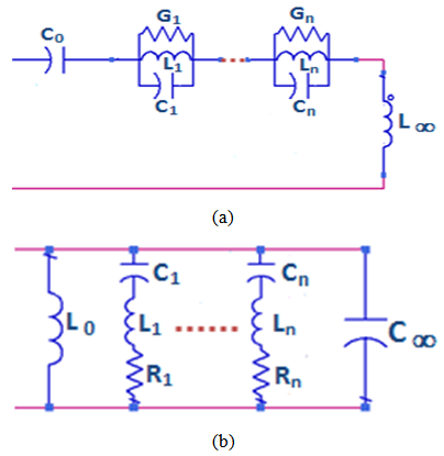 | Figure 1. Foster canonical forms of the equivalent circuit for (a) electric antennas and (b) magnetic antennas |
 | (1) |
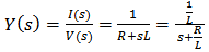
2.2. An Analytical Method Using Rational Transfer Function
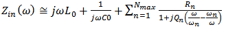
- A rational transfer function is a form of transfer function in Laplace domain consisting of numerator polynomials and denominator polynomials, whose coefficients can be determined by fitting simulation result [18]. The overall performance of an antenna can be characterized by a rational transfer function which yields the feasibility to combine the antenna with other components in the communication system rather than an independent part as in conventional design [18]. The rational approximation of a transfer function F(s) can be written as [19]:
 | (2) |
2.2.1. Equivalent Circuit with Real Values of resk and pk
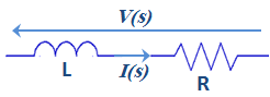
- Considering the RL series circuit of Fig.2, the admittance of the circuit can be easily calculated as [19]:
 | Figure 2. Equivalent RL circuit for real poles synthesis |
 | (3) |
 | (4) |
 | (5) |
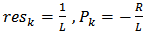
2.2.2. Equivalent Circuit with Complex Pair Values of resk and pk
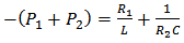
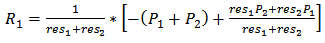
- Assume that res1, res2, p1 and p2 are complex pairs, then excluding the constant term and the s–proportional term, F(s) may be expressed as [19]:
 | (6) |

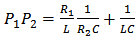
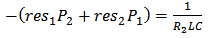
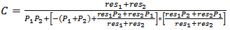
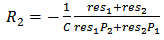
 Considering the RLC circuit shown in Fig.3, which is a combination of a simple series LR series and a CR parallel circuit, the admittance of the circuit, may be written in terms of its residues and poles as [19]:
 | Figure 3. Equivalent RLC circuit for complex pairs synthesis |
 | (7) |
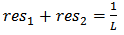 | (8) |
 | (9) |
 | (10) |
 | (11) |
 | (12) |
 | (13) |
 | (14) |
 | (15) |
 | Figure 4. SPICE-compatible equivalent circuit for antenna |
3. Simulation Results and Discussion
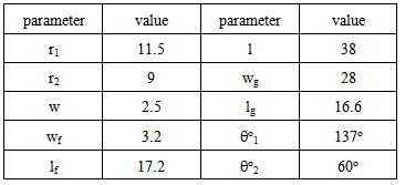
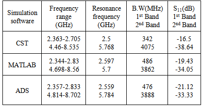
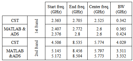
- The dual-band crescent-shape monopole antenna proposed in [16] was chosen as a typical dual-band antenna in this investigation. The details of the antenna design are shown in Fig.5, and Table 1. The model was designed to match the 50 ohm feed line. The impedance at the feed line reference port was obtained using CST Microwave Studio. The theoretical results were obtained by considering an equivalent circuit of the antenna using MATLAB and ADS for calculating input impedance of the antenna. The results obtained from MATLAB and ADS softwares were then compared with the results obtained from the simulated antenna using CST. The derivations of the equivalent circuit are presented in the following three sections.
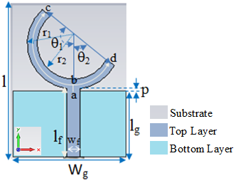 | Figure 5. Geometry of the dual band crescent-shape monopole antenna [16] |
|
3.1. Equivalent Circuit Derived from Reflection Coefficient Response
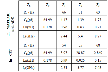
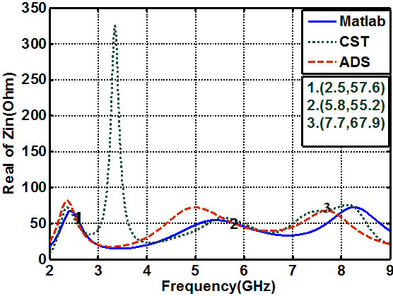
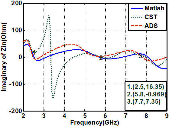
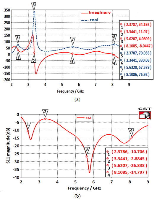
- Figure (6a) shows the reflection coefficient curves of the considered antenna as obtained from CST simulations. Each of the three sharp dips in the curve can be considered to represent a resonance frequency. In Fig. (6b) the variation of the input impedance with frequency is shown, where the points marked by 1 to 6 represent real and imaginary values for the corresponding points indicated in Fig.6a. It can be seen from Fig.6b that the values of the real part at these points are around 50Ω while the values of imaginary parts are nearly crossing the zero. This means that the above resonating frequencies occur at matching points. According to the figure, three anti-resonance modes are observed in the investigated bands. The results of Fig. 6 lead to propose the equivalent circuit shown in Fig. (7). Table 2 shows the element values of the equivalent circuit model for the designed antenna. The values of resistors, capacitors and inductors are extracted from the CST simulation results, where these values are adjusted manually to obtain the proper response (response in MATLAB and ADS are similar to that in CST simulation). C0 and L0 represent the capacitance and inductance of the monopole antenna when the antenna operates at lower frequency and are properly chosen to resonate at the first resonance frequency of the antenna [20].
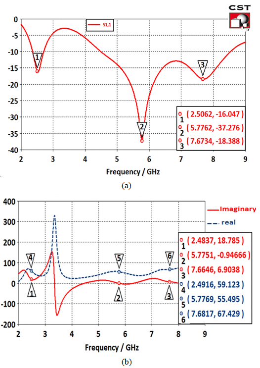 | Figure 6. Obtained results from CST software. (a)Reflection coefficient response, (b) the real and imaginary parts of (Zin) with frequency |
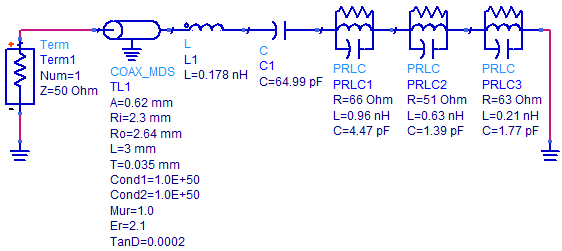 | Figure 7. Equivalent lumped-elements circuit model for antenna in ADS |
|
 | Figure 8. Variation of real part of (Zin) with frequency |
 | Figure 9. Variation of imaginary part of (Zin) with frequency |
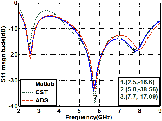 | Figure 10. Comparison of the reflection coefficient responses obtained from CST, ADS, and MATLAB |
|
3.2. Equivalent Circuit Derived from Input Impedance Response
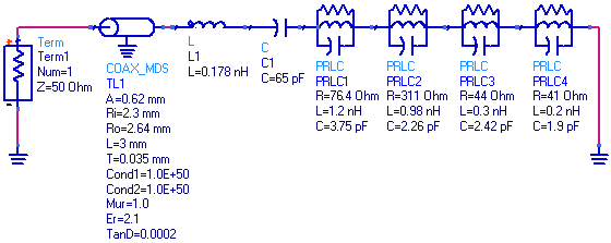
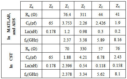
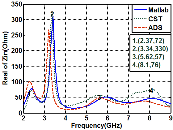
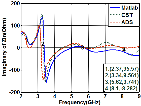
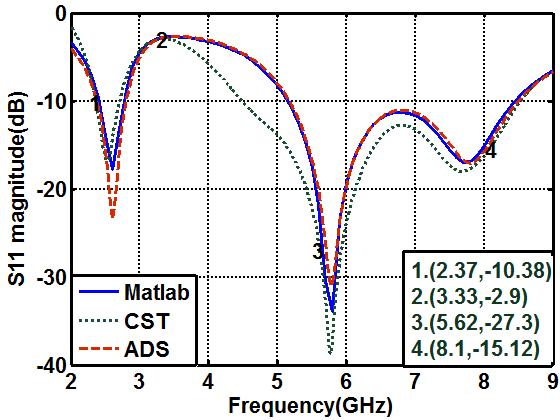
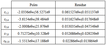
- Around the resonance frequency, the antenna behaves like a series RLC circuit, where the derivative of the antenna's reactance with respect to frequency is positive. Near ranges of anti-resonance the general antenna behaves like a parallel RLC circuit and the frequency derivative of the antenna's reactance is negative [21]. When the antenna reactance moves from a negative (capacitive) value to a positive (inductive) value, in a finite frequency range, the frequency derivative of the antenna reactance is positive. If the impedance of the antenna changes from a positive (inductive) reactance to a negative (capacitive) reactance in a finite frequency range, the frequency derivative of the antenna's reactance is negative [21]. Therefore, by examination of the frequency derivative curves with respect to frequency of the antenna impedance the antenna can be modeled by either series or parallel RLC circuits. Figure 11a, shows the input impedance responses of the antenna obtained from CST simulations. The input impedance is then represented by parallel RLC cells connected in series. At each mode, the imaginary part is nearly crossing the zero line and has a negative derivative while the real part has a local maximum. The proposed equivalent circuit model of the antenna is shown in Fig. 12. Figure 11b, shows the reflection coefficient response of the antenna. The points numbered from 1 to 4 represent the reflection coefficient for the corresponding points indicated in Fig.11a. As shown in the figures, the real part at point number 7 equals to 57.4Ω with S11=-26.838 dB. The real part at point number 5 equals to 70Ω, and S11=-10.7dB. The real part at point number 6 equals to 330Ω at S11= -2.88dB. As can be seen from Fig.12, and Table (4), the input impedance is represented by four parallel RLC cells connected in series. The first cell represents the first band which resonates at 2.375GHz, the second cell represents the resonance frequency at 3.33GHz, the third and fourth cells (3,4), which are resonating at frequencies 5.62 and 8.1GHz respectively, represent the second band.
 | Figure 11. (a) Variation of the real and imaginary parts of (Zin) with frequency. (b) Reflection coefficient response for the antenna |
 | Figure 12. Equivalent lumped circuit model for antenna in ADS |
|
|
 | Figure 13. Variation of real part of (Zin) with frequency |
 | Figure 14. Variation of imaginary part of (Zin) with frequency |
3.3. Antenna Model Derived from SPICE-compatible Equivalent Circuit
- The SPICE-compatible equivalent circuit modeling was applied to obtain equivalent circuit models of the input admittance. For example the dual-band monopole antenna, whose parameters are shown in Table 1, was considered.
 | Figure 15. Reflection coefficient responses versus frequency |
|
|
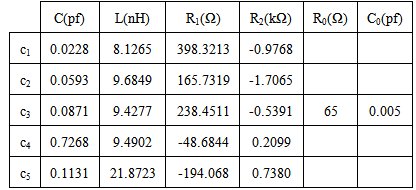
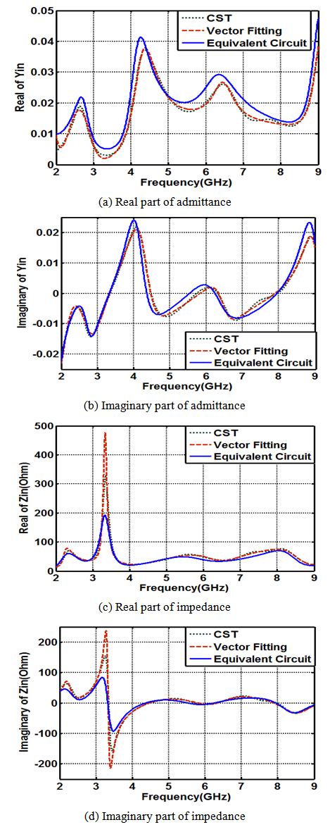 | Figure 16. Comparison of the admittance, and impedance parts of the antenna obtained from; CST simulation, the VF technique, and SPICE equivalent circuit |
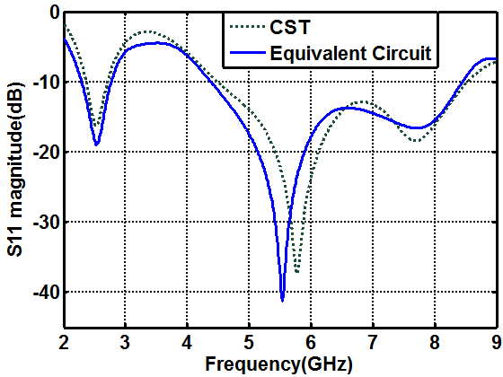 | Figure 17. Comparison of reflection coefficient of the antenna obtained by means of CST simulation and SPICE equivalent circuit |
4. Conclusions
- The modeling of a dual-band antenna has been demonstrated, a using crescent-shaped monopole antenna as a study case. An electrical model is applied to represent the input impedance of the antenna S two approaches. In the first approach, the input impedance is represented by parallel RLC-circuits connected in series. Each resonance is represented by a parallel RLC circuit derived either from the reflection coefficient response or the input impedance. The obtained results showed that the equivalent circuit extracted from the real and imaginary parts of input impedance gives good details about the whole studied band (from 2 to 9GHz). However, the equivalent circuit extracted from the reflection coefficient response gives good details about the design bands only (2.4, 5.2, and 5.8GHz). The second investigated approach is SPICE–compatible equivalent circuit using vector fitting technique. The formulation of the transfer function in rational polynomial can identify the poles and zeros of the antenna system. Each RLC circuit is proposed as an equivalent representation for a complex pole pair. The model responses using MATLAB and ADS showed good agreement with those obtained from the CST simulation. While most of the modeling methods have considered either narrow or UWB antenna, it has been demonstrated that the methods are equally applicable to dual band antennas.
ACKNOWLEDGEMENTS
- The authors wish to acknowledge valuable discussions with Prof RaedA.Abd-Alhameed / Bradford university, UK during the preparation of the manuscript.