Ali Azarbar, M. S. Masouleh, A. K. Behbahani
Department of Computer and Information Technology Engineering, Islamic Azad University, Parand Branch, Tehran, Iran
Correspondence to: Ali Azarbar, Department of Computer and Information Technology Engineering, Islamic Azad University, Parand Branch, Tehran, Iran.
| Email: |  |
Copyright © 2014 Scientific & Academic Publishing. All Rights Reserved.
Abstract
In this paper, different design of terahertz microstrip array rectangular patch antenna in the range of 0.5-1 terahertz is simulated. Multilayer technique to descend notch depth are applied. We used from Tetraflouroethilen (ε=2.08) in homogeneous substrate and we combined it with another material with ε=3.82 in two layer substrate as host material. To validate results which came from Ansoft HFSS commercial which are based on finite element method we used analytical method in operating frequency (600GHz). Least square genetic algorithm helped us to optimize geometrical parameters of array such as microstrip feed line and rectangular patch aspects.
Keywords:
Directivity, THz frequency, Wireless communication, Microstrip array antenna
Cite this paper: Ali Azarbar, M. S. Masouleh, A. K. Behbahani, A New Terahertz Microstrip Rectangular Patch Array Antenna, International Journal of Electromagnetics and Applications, Vol. 4 No. 1, 2014, pp. 25-29. doi: 10.5923/j.ijea.20140401.03.
1. Introduction
Terahertz (THz) radiation is electromagnetic radiation whose frequency lies between the microwave and infrared regions of the spectrum. The THz band does not have a standard definition yet. Unless we deal with ultra broadband THz pulses, we will use 0.1-10 THz as a universal definition of the THz band. Yet this part of the electromagnetic spectrum remains the least explored region mainly due to the technical difficulties involved in, making efficient and compact THz sources and detectors. The lack of suitable technologies led to the THz band being called the “THz gap". Over the last two decades, THz technology has ripened enough that a thorough summary and review of the relevant topics is in order and this technological gap has been rapidly diminishing for the last two decades. Besides, the THz community is growing fast and the THz technology is in a transitional period. The THz research activities have mainly focused on generation and detection until lately, but the focal point has shifted to the practical applications such as high-speed communication, molecular spectroscopy, security imaging, and medical diagnosis, among many others. Terahertz imaging is tested in process and quality control in manufacturing of aircrafts, cars, drugs and computer chips. Furthermore, terahertz imaging is considered for security applications such as screening for concealed weapons. Much of the scientific interest in T-rays is due to the unique properties of this type of radiation. Unlike X-rays, THz waves have very low photon energy and thus cannot lead to harmful photo ionization in biological samples. THz waves are also transparent to most like wood, paper, cloth, and plastic and as such suffer less scattering than visible and IR waves due to their longer wavelengths. Furthermore, many biological and chemical compounds exhibit characteristic absorption and dispersion signatures in the THz regime due to vibration and rotational transitions. This implies that THz Radiation might be used to examine the chemical composition of such compounds. Together, these properties make T-rays an excellent source for medical diagnostics and non destructive evaluation type of application. In communication systems Microstrip patch array antennas aredesirable components for wireless communication due to their higher gain and directivity with respect to single patches. Kumud R. Jha and G. Singh [1] design a single patch microstrip antenna, Aditi Sharma &G. Singh [2] design an Rectangular Microstirp Patch Antenna for Short Distance Wireless Communication System. In many cases microstrip patch antenna radiate along ground plane. This radiation cause undesirable radiation pattern. Furthermore in array antenna this phenomenon increases mutual coupling between patches. At large numbers of papers in this field of research investigated some parameters as VSWR, bandwidth of microstrip array antennas, directivity and gain are investigated [3-4].
2. Design Procedure
2.1. Array
Patch array is used in terahertz band to enhance antenna gain and directivity. Due to fabrication simplicity and aforementioned benefits, symmetric direct coupled is feed used for radiating elements, but by increasing number of elements feeding problem like mutual coupling between feed line and patches or even between patches will appear, to overcome such problems, surface wave must be considered. The layout of the proposed antenna is shown in Figure 1.
2.2. Multilayer Technique
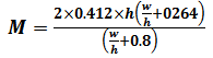
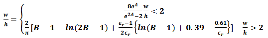
Generally multilayer substrate technique is useful for several respects, but enhancing bandwidth of antennas is prominent cause. Multilayer microstrip antennas have wide bandwidth compared to homogeneous one. They have another specification such as multi frequency resonance points and higher gain. Although multilayer technique enhances antenna gain but its main results is in improving band width of antenna, as it mentioned in terahertz regime, antenna gain and directivity is much more important than band width due to atmospheric damping for signals, and if they even have narrow bandwidth they still be practical because herein bandwidth will be equal to hundreds of Megahertz. When the bandwidth of antenna increase, unavoidably quality factor will be decreased and it result in reduction in directivity and gain of antennas. Multi frequency application of such these antenna by means of multilayer technique is applicable for inspections and surveillance systems in terahertz band. For controlling radiation characteristic and impedance bandwidth of terahertz microstrip antenna geometrical parameters of a patch which design on multilayer substrate is so important. Particularly if microstrip line use for feeding, inevitably it increases thickness of substrate and propagation characteristic is governed by number of layers between ground plane and strip lines. In terahertz frequency generally permittivity has main role, to determine geometrical aspects of microstrip antenna. In the microwave frequency range, the geometrical configuration of the patch antenna on the thin substrate is governed by following equations: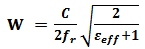 | (1) |
 | (2) |
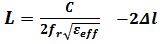
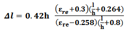 | (3) |
In the above equations, W and L are the width and length of the radiating patch, respectively. C is the velocity of the light in free-space. fr and h are the resonance frequency and substrate thickness, respectively. When W/h ratio is fixed from (1) for a given effective dielectric permittivity of the material, the  can be easily written in terms of eeff and the substitution of the value of
  in (2) makes L dependent on eeff at a given resonance frequency provided eeff>0.258. Furthermore, (2) can be written in the following form:
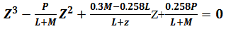 | (4) |
 | (5) |
 | (6) |
 | (7) |
Design procedures commenced by selecting tetraflouroethilen as substrate (ε=2.08) we assume thickness of substrate h=30 μm thus by using above formulas, the calculated value of length (L) and width (W) of the microstrip patch antenna are 131.567 μm and W=86.873 μm.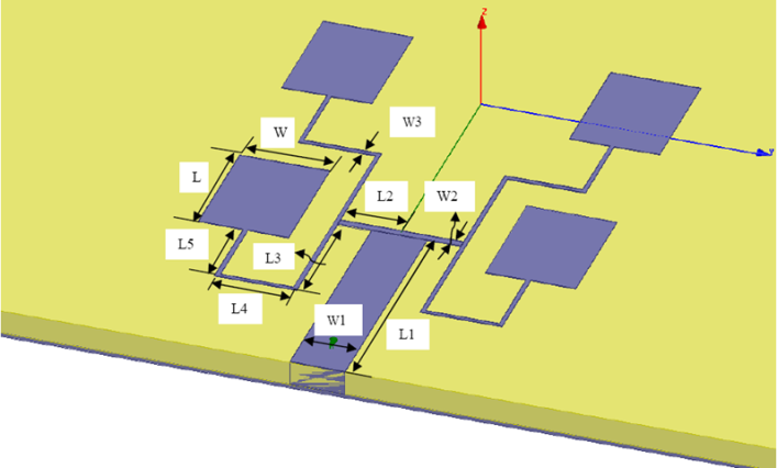 | Figure 1. Proposed array microstrip antenna |
2.3. Feed
To select one kind of microstrip antenna for particular application, exciting devices of radiating patches are indispensable part of design, and must be mentioned. There are so many kinds of feeding method, which not apply just for coupling energy to radiating elements while they use to distribute energy regularly to planar and linear arrays. There are some important notes, which must be considered in feeding method such as energy transferring with high efficiency that comes from impedance matching between radiator patches and feeding structure. Transformers such as step transformers, bends, stubs, junctions and so on, seems useful at first and can be used in array feeding design but they cause discontinuity in feeding lines which result in spurious radiation and surface wave losses. Which they result in increasing side lobe levels and cross-polarization in radiation pattern, thus minimizing spurious radiation and its effects on radiation pattern is one of main factors for selecting feeding structure. There are several choices to feed terahertz microstrip array antenna, for realization we try to choose a kind of feeding method which has less complexity for fabrication and spurious radiation from feeding structure in terahertz range of frequency for example at the first, coaxial feed method seems impressive due to less mutual coupling between feed line and patches but it has some disadvantages which influence its benefits such as: difficulty to obtain match for thicker substrates due to probe inductance and significant probe radiation and surface wave radiation for thicker substrate in terahertz range. More over coaxial feed needs much more junctions and because of very small size of antenna in terahertz band fabrication seems so hard. Inset-feed is another kind of feeding method, and it has some problematic condition, like for example, significant line radiation for thicker substrate for deep notches pattern may shown distortion. In this paper, direct symmetric coupled patch for feeding structure isproposed. It has less constraint compared with some other feeding such as simplicity in fabrication less spurious radiation from feed line compared with coaxial probe, and its less complexity to obtain input matches allows for planar feeding. To feed the radiating patch, we have used a microstrip transmission line by using of formula which is presented in [6]: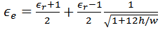 | (8) |
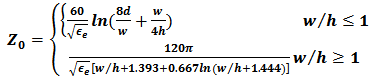 | (9) |
 | (10) |
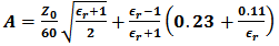 | (11) |
 | (12) |
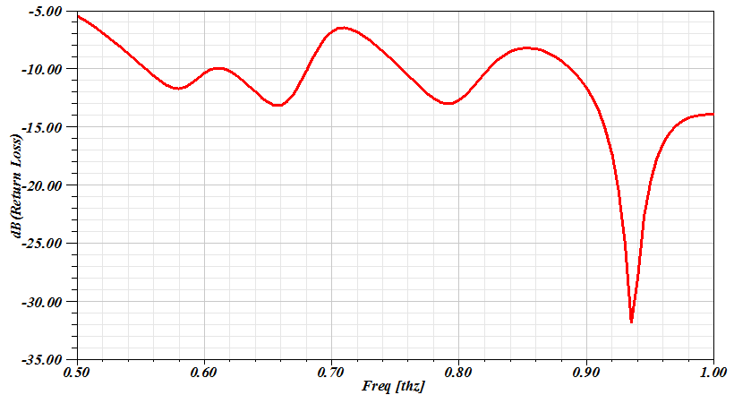 | Figure 2. S11-parameter of the antenna designed on homogeneous substrate without optimizing in geometrical parameters |
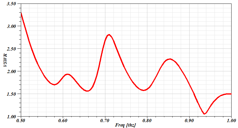 | Figure 3. VSWR of the antenna designed on homogeneous substrate without optimizing in geometrical parameters |
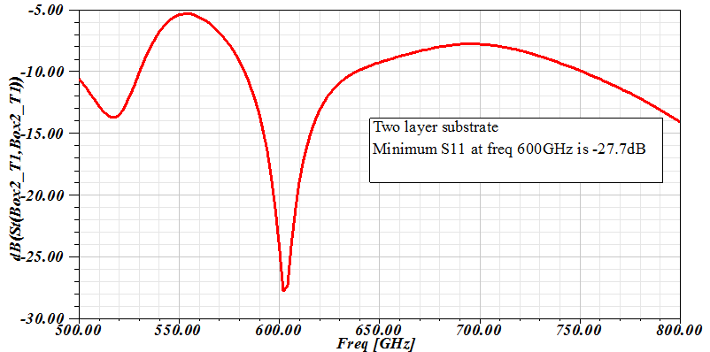 | Figure 4. S11-parameter of the antenna designed on two layer substrate with optimizing in geometrical parameters |
By using above formulas, the length and width thick feed line is equal to 52.347μm and 300μm. The length, width, and height of the substrate are 2000μm, 2000μm, and 30μm, respectively. The ground plane, radiating patch, and feed-line are made of copper of thickness 20μm, respectively. This proposed structure is simulated in Ansoft HFSS commercial version. When this structure is simulated, the antenna resonates around 600 GHz but resonant frequency doesn't have deep notche. To tune the antenna for the intended resonance frequency of 600GHz.figure 2&3 shows return loss and VSWR of proposed antenna on homogeneous substrate.This proposed structure is simulated in Ansoft HFSS commercial version with lump-port excitation. When this structure is simulated, the antenna resonates at unspecified point. For two layer substrate we selected h1=21.54 with ε1=2.08 and h1=28.46 with ε1=3.82. To tune the antenna for the intended resonance frequency of 600GHz, further more for enhancement in gain and directivity, the parametric optimization has been carried out and finally the value of L and W are selected equal to 100.7689 and 150.93025 μm, respectively. The comparison of S11 parameter (dB) which is shown in Figure 2 and 4 shows improvement in electrical parameter of optimaized antenna with two layer. In the case of optimized model the antenna resonates at 600 GHz, whereas in the case of Ansoft HFSS simulation, the resonance frequency is equal to 620 GHz. A difference of 20 GHz in the resonance frequency obtained by using these two proposed technique is noticed. On this way, the deviation in result is attributed to the difference in the excitation technique. However, it indicates that the proposed antenna is also compatible to 50Ω terminal characteristic impedance which is normally a standard in the industry. The -10 dB fractional bandwidth (FBW) of the antenna in these two cases are 130GHz and 58 GHz respectively.| Table 1. Optimized geometrical parameters of proposed microstrip array |
| | Geometrical parameters | Values (μm) | | W | 109.7689 | | L | 150.93025 | | L1 | 300 | | L2 | 150 | | L3 | 100 | | L4 | 100 | | L5 | 100 | | W1 | 67.185 | | W2 | 9.913693 | | W3 | 5.306634 |
|
|
3. Conclusions
In this paper, a terahertz microstrip array rectangular patch antenna is simulated. The electrical parameter of antenna optimized with using of two layer and least square genetic algorithm.
References
| [1] | Jha, K.R., Singh, G.’ Analysis and design of rectangular microstrip antenna on two-layer substrate materials at terahertz frequency’ J. Comput. Electron., 68-78 (2010). |
| [2] | Sharma, A., Singh, G.: Rectangular microstrip patch antenna design at THz frequency for short-distance wireless communication’. J. Infrared Millim. Terahertz Waves, 1-7 (2009). |
| [3] | Ghassemi, N., Rashed-Mohassel, J., Neshati, M.H., Tavakoli, S., Ghaaemi, M.’ High gain dual stacked aperture coupled microstrip antenna for wideband applications’. Prog. Electromagn. Res. 125-135 (2009). |
| [4] | Sharma, A. Dwivedi, K. V, and Singh, G., ‘THz Rectangular Patch Microstrip Antenna Design Using Photonic Crystal as Substrate’ Progress In Electromagnetics Research Symposium, Cambridge, USA, 2008 |
| [5] | Mueller, E. and A. J. DeMaria, “Broad bandwidth communication / data links using terahertz sources and Schottky diode modulators/detectors," Proc. SPIE, Vol. 5727, 151-165, 2005. |
| [6] | Balanis. C. A, “Modern Antenna Handbook”. Wiley Publisher, 2008 |
 Abstract
 Reference
 Full-Text PDF
 Full-text HTML