-
Paper Information
- Previous Paper
- Paper Submission
-
Journal Information
- About This Journal
- Editorial Board
- Current Issue
- Archive
- Author Guidelines
- Contact Us
International Journal of Electromagnetics and Applications
p-ISSN: 2168-5037 e-ISSN: 2168-5045
2013; 3(6): 136-143
doi:10.5923/j.ijea.20130306.02
Compact Broadband CPW-fed Taper-shaped Monopole Antenna with L-slots for C-band Applications
 Abstract
 Reference
 Full-Text PDF
 Full-text HTML
Dhirgham K. Naji
Department of Electronic and Communications Engineering, College of Engineering, Alnahrain University, Baghdad, Iraq
Correspondence to: Dhirgham K. Naji, Department of Electronic and Communications Engineering, College of Engineering, Alnahrain University, Baghdad, Iraq.
| Email: |  |
Copyright © 2012 Scientific & Academic Publishing. All Rights Reserved.
A design approach for the compact broadband coplanar waveguide (CPW)-fed tapered monopole antenna (TMA) for C-band applications is presented, in this paper. The proposed antenna is composed of a CPW-fed monopole antenna with tapered structures, embedded with symmetric open-ended L-slots, and a tapered shape is cut from the top sides of the CPW-fed ground plane. By loading these structures, the return loss (S11) bandwidth is noticeably increased due to adjacent three resonance modes are generated from the monopole antenna. The designed TMA is simulated by electromagnetic simulator (CST Microwave Studio), with obtained optimal parameters, is demonstrated that  impedance bandwidth is ranging from 3.8 to 8 GHz. The overall dimension of the antenna comes at
 This antenna has the advantages of simple configuration, low profile, compactness, and low fabrication cost. The design process and the parametric study of key parameters (taper and slot structures) in producing broadband antenna bandwidth are analyzed and discussed in detail. The simulated results demonstrate that the proposed TMA has good stable omnidirectional radiation patterns, and the peak gain and maximum efficiency over the operating band are 3.4 dBi and 95%, respectively.
Keywords: Broadband, Compact, Coplanar Waveguide, C-band, Tapered Monopole Antenna
Cite this paper: Dhirgham K. Naji, Compact Broadband CPW-fed Taper-shaped Monopole Antenna with L-slots for C-band Applications, International Journal of Electromagnetics and Applications, Vol. 3 No. 6, 2013, pp. 136-143. doi: 10.5923/j.ijea.20130306.02.
Article Outline
1. Introduction
- In the recent years, with the rapid development of modern wireless and mobile communications, there has been great interest in wideband antenna designs. Many applications require antennas with compact size, multiband and/or broadband impedance bandwidth, stable gain and radiation pattern[1]. It is a well-known fact that microstrip planar antennas are characterized by their interesting features; lightweight, low-profile, low cost, small size and ease of fabrication. However, the conventional patch antenna suffers from a very narrow impedance bandwidth (less than 5%), which cannot satisfy the bandwidth requirement of the modern wireless systems[2]. Thus, different techniques for bandwidth enhancement are reported in literatures, such as the aperture coupled feed[3]–[5], stacked patches[6]–[9], coplanar coupled feed[10], L-probe feed[11],[12], E-shaped patch[13]–[16] and U-slot patch[9],[17]. By using these techniques, great enhancement on impedance bandwidth up to 50% has been attained for VSWR < 2. All these antennas based on slot structures are smaller than conventional monopole antennas but their structures are much more complex for practical applications.Recently, many researchers have paid great attention for improving the antenna bandwidth by employing the coplanar waveguide (CPW)-fed line since it has many features, such as simple structure, compact size, low cost, omnidirectional radiation pattern across the all operating bands and easy integration of monolithic microwave integrated circuits (MMIC)[18]. Hence, the CPW-fed planar slot antennas are identified as the most promising antenna design for wideband wireless applications[19]-[26]. Thus, CPW-fed method is adopted here to design the proposed antenna.In this paper, a new broadband antenna for C-band application is presented. The proposed antenna composes of a beveled CPW ground plane, taper-shaped monopole radiator and open-ended L-shaped slots. The L-shaped slots embedded in the monopole with tapered-structure are a new approach to broaden the bandwidth of an antenna. The principle and simulation analysis of the tapers and slots in achieving broadband bandwidth of an antenna is given in detail. Also, parametric study of the key parameters including the length and width of the slots and the indentation angles of the taper structures are also simulated and discussed. The broadband CPW-fed tapered monopole antenna (TMA) has a compact size of
 and the achieved bandwidth covers 3.8-8 GHz for C-band application.
2. Proposed Antenna Configuration and Design Consideration
- Normally, the bandwidth of the microstrip antenna is narrow since it has only one resonance frequency. The bandwidth may be broadening if there more resonant parts are available with each one operating at its own resonant mode. Therefore, this leads to multiband or broadband performance due to the overlapping of these multiple resonances. Thus, a modification must be done in the geometry of a microstrip antenna to support the multiresonance. The principle that aforementioned above is adopted here for designing the proposed antenna. The configuration with detailed dimensions of the proposed CPW-fed tapered monopole antenna (TMA) is demonstrated in Fig. 1 and the various antenna structures involved in the design evolution process for broadband operation are shown in Fig. 2. All designed antennas are printed on a FR4 substrate of height
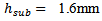 with relative permittivity,
  and the overall occupied area is characterized by substrate length and width,
  respectively, i.e.,
  The basis of the monopole radiator is a rectangular shape, which has the dimensions of length
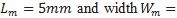
 Afterwards, the structure is modified to form a tapered shape of indentation angle
  at each side of the monopole width. The width of the CPW feed line is fixed at
 and a gap distance of
  between the signal strip and the coplanar ground plane of length
 is used to achieve
  characteristic impedance. The feed line is terminated with a standard SMA connector. The TMA is connected to CPW-strip line and placed at a distance of
  from the top of CPW ground plane. An open-ended L-slot, is positioned at the centre of tapered- monopole structures, and characterized by its lengths and widths,
 respectively. Finally, a pair of
  -tapered structure is cut from the top of two-sided CPW ground plane. The electromagnetic simulation software CST Microwave Studio ver. 2012 is used to design the proposed antenna.
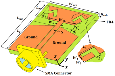 | Figure 1. Geometry of the proposed CPW-fed slot antenna for C-band applications.    (Unit: mm) (Unit: mm) |
 and the lowest frequency of operation
  are given. Then, substrate length
  and substrate width
 of the antenna are calculated as
 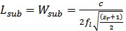 | (1) |
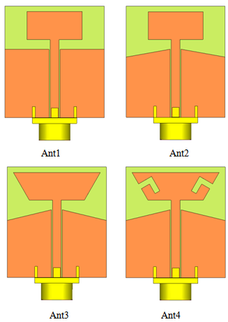 | Figure 2. Four improved prototypes of the proposed CPW-fed slot antenna |
 is speed of light. Note that the length and width of the antenna structure, according to (1), are equal to half of the effective wavelength at the lower frequency
 From (1), one can found that
 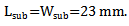 Afterwards, the CST software is used to sweep each geometric parameter and then the results are fine-tuned until the required resonance frequency with reasonable bandwidth is achieved. As shown in Fig. 3, this design can excite one resonant mode near
  ranging from
  to
to In order to broaden the antenna bandwidth to satisfy C-band operation
  Ant 2 is realized by cutting the CPW ground of Ant 1 by tapered structure of angle
 It generates two-resonant modes, one at
  and is capable of operating over the
  frequency range, as noticed in Fig. 3. Thus, the bandwidth is increased without enlarging the size of antenna. It is seen that the lower frequency range
 is nearly unaffected, whereas, the upper frequency range
  is increased from 6.3 GHz to
  when Ant2 is introduced. It needs other modification in Ant2 to increase
  toward
 the upper range of C-band application. Therefore, Ant3 is proposed for this purpose, which contains other tapered structure of angle
  added to the vertical side of the monopole antenna. As seen from Fig. 3, two resonant-modes of
  and
and  are produced and more bandwidth of
  ranging from
  is achieved compared with Ant2 bandwidth of
 It is still that higher frequency range has not satisfied; this leads to introduce Ant4 to perform this requirement. Open-ended L-slots are added to the tapered-monopole structure of Ant3 to increase the perimeter length of the radiating structure which enhances the antenna bandwidth significantly. This can be seen from Fig. 3, where the bandwidth of C-band application is performed which is about of
  to
to The reason behind that is due to the generation of higher resonant-mode of
  in addition to the lower resonant-modes of 4.2 and
  that achieved from Ant3. Thus, the Ant 4 (proposed antenna) is capable of satisfying the C-band application, i.e.,
  band.
band.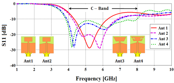 | Figure 3. Simulated S11 results for antennas 1-4 (for CPW-fed slot antenna with optimized values of the designed parameters) |
 | Figure 4. Simulated results of (a) gain (G) and (b) efficiency  of the proposed antenna (Antenna 4) of the proposed antenna (Antenna 4) |
3. Simulated Results and Discussion
- The radiation characteristics such as antenna peak gain and radiation patterns across the operating bands for the proposed antenna have also been presented and discussed. The simulated gain and efficiency variations with frequency are shown in Fig. 4(a) and (b), respectively. The obtained gain and efficiency are between -0.8 and 3.4 dBi, and 50 and 95%, respectively with nearly stable gain are obtained about 2 dBi and 3 dBi over frequency ranges,
 and
and respectively. The simulated radiation patterns are shown in Figs. 5 and 6. The 3D and 2D patterns are simulated and depicted at three different frequencies (resonant-modes of Ant
 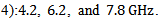 Fig. 5 presents 3D farfield gain patterns for the aforementioned three frequencies, as shown, an omnidirectional and stable radiation patterns are achieved for low and middle frequency bands, see Fig. 5(a) and (b). But at high frequency band, Fig. 5(c), nearly omnidirectional with unsymmetrical pattern about xz-plane is obtained. The 2D absolute gain patterns in the yz- or E-plane and xz- or H-plane are seen in Fig. 6 for frequencies, 4.2, 6.2 and 7.80.GHz. It seen that an omnidirectional pattern are sustained in H-plane (xz-plane) over all the frequencies in the C-band. But a figure of 8 is obtained for lower and middle frequencies, Fig. 6(a) and (b), and distorted version of figure 8 is seen for higher frequency in the band, see Fig. 6(c).
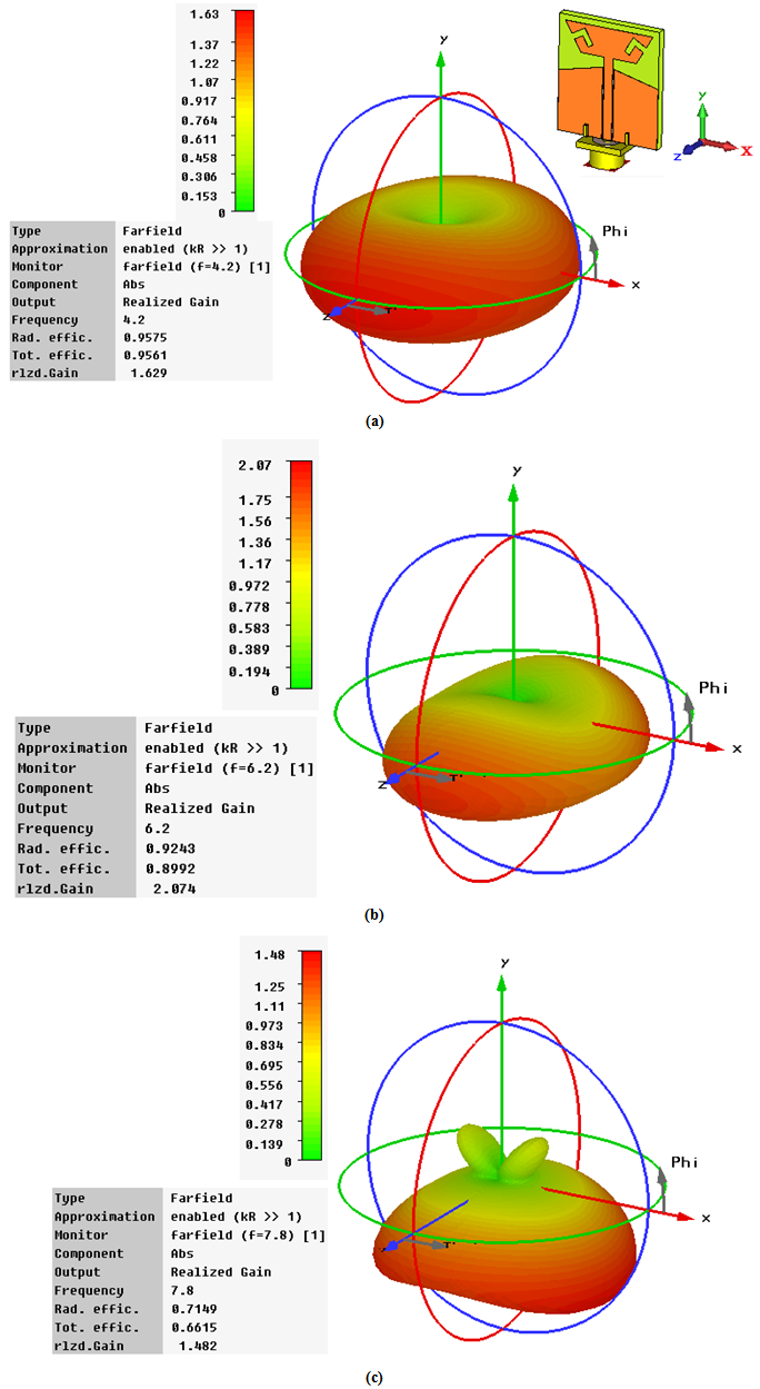 | Figure 5. Simulated results of 3D farfield gain patterns at  for the proposed antenna (Antenna 4) for the proposed antenna (Antenna 4) |
 | Figure 6. Simulated radiation patterns for the proposed antenna (Ant 4) at (a) 4.2 GHz (b) 6.2 GHz (c) 7.8 GHz |
4. Key Parameters Study
- In this section, the key parameters of the antenna are investigated to show their influences on the antenna performance. The angles
 of the tapered monopole and CPW ground, respectively, and the lengths and widths of L-shaped slot
  respectively. These parameters are especially examined to study their influences on impedance bandwidth. All other parameters keep their initial values as seen in Fig. 1.
4.1. Effects of the Tapered Structures
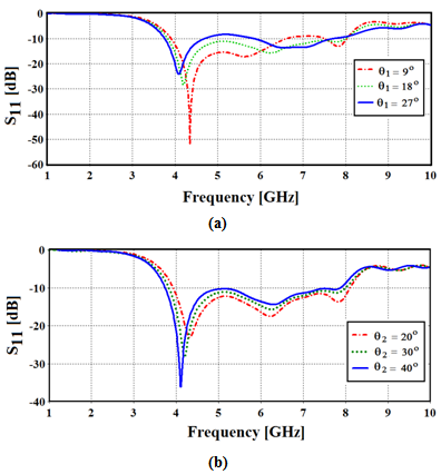 | Figure 7. The simulation results for S11 as affected by parameter (a)  (b) (b)  |
 of the taper-shaped structures are investigated to find their effects on the antenna performance. We can see that the antenna’s return loss is greatly affected by the ground CPW taper angle
 Fig. 7(a), while less effect is observed for the tapered monopole angle
  on antenna's return loss, Fig. 7(b). As
  the lower resonant-mode is increased from 4.1 to 4.3 GHz with best value
  for 4.2 GHz resonant-mode, but higher resonant-mode 7.8 GHz is unaffected for angles less than
  and it disappears for angles greater than
 . In Fig. 7(b), lower resonant-mode is decreased when
  is increases while higher resonant-mode is decreased slightly with increasing in
 .
.4.2. Effects of the L-Shaped Slot
- The effect of the important parameter, L-shaped slot, on the antenna performance, return loss is demonstrated in Figs. 8(a)–(b). It is seen from Fig. 8(a), the length
 is influences only on higher resonant-mode and not affect on lower resonant-mode. For
 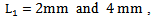 the higher frequency band is reduced from
 to
to and the bandwidth is only
 has nearly not changes the return loss when it is varying from
  see Fig. 8(b). Also, as seen from Fig. 8(c), the width
  is approximately has not affect on the antenna's return loss when it is varying from
  to
to Finally, as depicted in Fig. 8(d), the width
  has little effect on lower resonant-mode, but more effect has been observed at higher resonant-mode, hence, on the bandwidth when it is varying from
  It is concluded from the previous discussion that the tapers and L-shaped structures have great influences on the higher-resonant mode and less affect on the lower resonance-mode Also, three out of the six parameters,
  and
and  play an important rule for achieving great enhancement in antenna bandwidth.
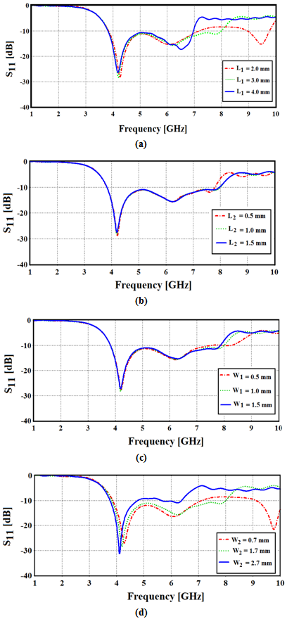 | Figure 8.   |
5. Conclusions
- In this paper, coplanar waveguide (CPW)-fed tapered monopole antenna (TMA) for C-band application

 has been proposed and simulated using taper and L-shaped structure. The concept of resonant-mode frequencies overlapping technique is used to get wide bandwidth via adding resonant geometrical parts to the antenna. A compact size of TMA structure is obtained from the design process
  Additionally, the antenna exhibits a simulated dB return-loss bandwidth of 4.2 GHz ranging from 3.8 to 8 GHz, while maintaining a high efficiency and gain in the order of 95% and 3.4 dBi at the bands of interest. It is therefore well suited for C-band applications. These applications include IEEE 802.11b/g wireless network standards (5.15-5.35 GHz and 5.725-5.825 GHz), communications satellites, satellite radio, weather radar, etc.