Khalil H. Sayidmarie, Qusai H. Sultan
Department of Communication Engineering, College of Electronic Engineering / University of Mosul, Mosul, Iraq
Correspondence to: Khalil H. Sayidmarie, Department of Communication Engineering, College of Electronic Engineering / University of Mosul, Mosul, Iraq.
| Email: |  |
Copyright © 2012 Scientific & Academic Publishing. All Rights Reserved.
Abstract
Synthesis of wide-beam array antennas is investigated using phase-only technique. A quadratic phase distribution for the element excitations is proposed, while the magnitudes are kept uniform. The beam width and maximum level of the radiated field of the proposed array were compared with those obtainable from the conventional broadside array. Compared to the case of broadside array, the proposed method showed many fold increase in the -10dB beam width. Moreover, a reduction of up to 7.6dB for a 10-element array, and 13.6dB for the 40-element array have been obtained in the maximum level of the pattern. The proposed technique offers simple design method, and considerable reduction in the number of required phase shifters. The required number of phase shifters for an N-element array is (N/2-1), and (N-1)/2 for even, and odd number of elements N respectively.
Keywords:
Array Synthesis, Wide Beam Arrays, Phase-only Excitation, Array Antennas
Cite this paper: Khalil H. Sayidmarie, Qusai H. Sultan, Synthesis of Wide Beam Array Patterns Using Quadratic-Phase Excitations, International Journal of Electromagnetics and Applications, Vol. 3 No. 6, 2013, pp. 127-135. doi: 10.5923/j.ijea.20130306.01.
1. Introduction
The need for antennas having wide beam patterns, as opposed to pencil beam ones, arises in many civil and military applications, including satellite communications, terrestrial wireless networks, and radar systems[1,2]. Electronic beam shaping of phased array antennas makes them very suitable for these applications. By choosing proper element weights, beam patterns with arbitrary shapes can be generated[2]. The desired beam pattern differs from one application to the other. For example, narrow beam width with reduced side lobe level is necessary for tracking radars, while search radars require wide beam width to cover more area in their range cell.Various antenna elements of sizes comparable to the wavelength usually have wide beam radiation patterns. A half-wave dipole has beam width of 78o, and the conventional microstrip patch antenna usually has radiation pattern covering most of the half space. When the antenna is designed in the form of an array, to utilize the design flexibility and many benefits of arrays, then the resulting pattern will have beam width that is inversely proportional to the size of the array. Pencil beam antennas have found huge number of applications, and raised much interest[1-3]. However, wide beam patterns are essential to many applications in various military and civil fields. Therefore, many techniques have been investigated to synthesize arrays that can offer wide beam patterns.In[4] the feasibility of broad-beam pattern synthesis using leaky-wave antennas (LWA) was proposed. The synthesis was based on a geometrical-optics approach and was achieved by a nonstandard tapering of a straight LWA, which involves the variation of both phase and leakage constants (magnitudes) of leaky-mode propagating along the structure. The relevant theory was provided together with examples of broad-beam pattern synthesis. The method tries to find magnitude and phase values along the antenna which are necessary to achieve a wide beam. There are numerous numerical optimization algorithms that have been used to find a minimum of a given objective function. The success of these methods depends on how well the designer has translated the desired specifications of the antenna into an objective function which, when optimized, provides the required performance[5]. If this function is not chosen properly one might get its optimum value yet the obtained solution might not achieve the synthesis goals. In[6] two different approaches for generating wide beam patterns were proposed. In the first approach, the problem was modelled as a second order cone program (SOCP), where the weights of elements were used as the optimization parameters. The global optimal solution to that model can be achieved by any SOCP solver. In the other approach, all the antenna elements were assumed to work at the same power level (uniform element magnitudes). By choosing only the element phases as the optimization parameters, a non-convex optimization problem was constructed. Particle swarm optimization (PSO) was then employed for finding the best solution[6]. The simple Fourier transform relation between the complex weights of the array elements and the corresponding antenna pattern has been utilized to propose various weights or aperture tapers to design antennas having patterns of various characteristics. Different antenna patterns can be generated by deploying various amplitude-only, phase-only, as well as phase and amplitude distributions on the elements of the phased array[7,8,9,10]. In general, wide range of compromise between the pattern parameters such as beam width, side lobe level and their decay rate, as well as antenna gain can be performed. Since controlling the amplitude of each element is not always practical, as it may need unconventional signal splitters (having specific ratios), beam synthesis using only phase shifters is of increasing interest.In this work, synthesis of wide beam array patterns using phase-only distribution is investigated. The proposed approach is to use quadratic phase distribution for the element weighting. The pattern beam width and maximum level of the radiated field obtained from the proposed method were compared with those obtainable from the conventional broadside array. The paper is organized as the following. The array formulation is described in Section 2. The quadratic phase excitation is analysed in section 3, and the effect of the number of elements is presented in section 4. Finally the conclusions are elucidated in Section 5.
2. Formulation of the Problem
Consider a linear array of N-elements centred with respect to the origin and placed along z-axis. The spacing between adjacent elements is (d) as shown in Fig. 1. Using the 1st element as a reference, the array factor can be written as: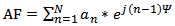 | (1) |
where;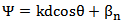 | (2) |
 is the wave number, and λ is the wavelength. an, and βn are the amplitude, and phase excitations of the nth element respectively. Since the interest here is in phase-only excitations, the amplitude excitations are made equal to unity (an=1) then the array factor will be:
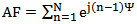 | (3) |
It is known that directive or a pencil-beam antenna has the property, where the radiated fields due to all array elements add constructively in the main beam direction, while the addition is mainly destructive in all other directions. For wide beam arrays, quasi-constructive addition is desired along wider range of angles in the visible range. This can be achieved by supplying proper distribution for the phase excitation (βn 's in Eq.2) to the array elements, since the process is phasing and addition of the vector contributions of the elements. The phase of the element contribution is caused by two factors; the first is the supplied phase to each element of the array (βn in Eq. 2). The second factor is due to the path length difference caused by the look angle to the array and the spacing between its elements (kd cos θ in Eq.2). Therefore, the solution is approached here by supplying the array elements by a certain phase excitation set which reduces the possibility of constructive addition of all the contributions of the array elements. The following section presents investigation of the proposed phase excitation to obtain wide beam patterns.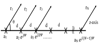 | Figure 1. Geometry of an N-element array |
3. Quadratic Phase Distribution
In this method a quadratic phase distribution is supplied to the elements of the array to widen its main beam. Consider the same array shown in Fig. 1 is supplied with the following phase excitation: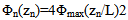 | (4) |
Where Φmax is the maximum phase value at the two edge elements of the array, and zn is the coordinate of the nth element along the array of length L where: 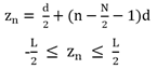 | (5) |
 | (6) |
Substituting into Eq. 3, the array factor can be written as: | (7) |
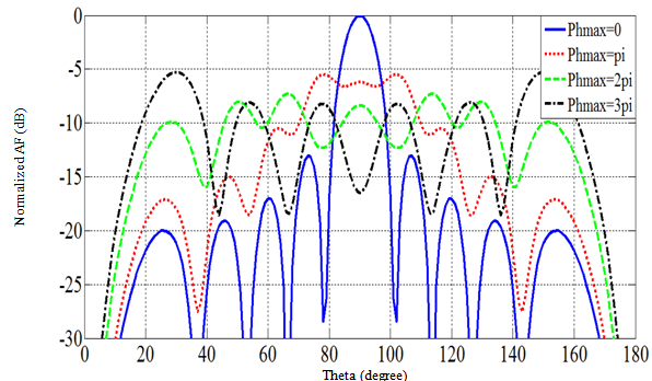
Figure 2 shows the phase excitation sets for the cases of  and the elements positions in a 10-element array considered in the simulations. For an even number of elements, there are M pairs of elements (M=N/2). Each pair of elements, which is symmetrically located about the array center, is given the same quadratic phase value, thus the needed phase values, and phase shifters for the implementation, are N/2. The phase values [β1, β2, β3 …βM] are supplied to the [1st, 2nd, 3rd, …, Mth] pair respectively as shown in Fig. 2.The array factors of the proposed array for various phase excitation sets are plotted in Fig. 3. It can be seen that when (Φmax=0) the case is the conventional broadside array which has a -10dB beam-width of 17o for the shown array of N=10 elements. The level of the main beam, for the case Φmax=0, was normalized to 0dB, while the other patterns for various values of Φmax were normalized to the same above value. It can also be seen from the figure that when
  the maximum value of the pattern has dropped down to -5.48dB. The width of the radiated field is much larger and it is found to be 76o. The main beam gets wider to 150o, and 154o as Φmax is increased to 2π, and 3π respectively. The maximum level of the wide beam also drops to -7.29dB, and -5.288dB as Φmax is increased to 2π, and 3π respectively. The pattern drops in level and shows wider beam width as Φmax is increased. It can also be seen that the radiation pattern has ripples whose peak to peak values increases as Φmax is increased.
 | Figure 2. The proposed quadratic phase sets for an array of 10 elements, separated by 0.5λ |
 | Figure 3. The array factor of a 10- element array, separated by 0.5λ, for various quadratic phase values Φmax |
The investigation aims to find which phase value (Φmax) at the edge elements should be used to achieve the desired reduction in the level of the main beam and obtaining wider radiation. This process needs a quantitative assessment of the obtained patterns, which is approached through the following two measures. The first measure of performance is the maximum value of the radiated field normalized to the number of elements N. This is called normalized maximum, and is defined as: | (8) |
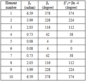
This value is unity or 0dB for the broadside array (Φmax =0). For other phase excitation values (Φmax > 0) this measure indicates to what level the main beam has been reduced.The second measure is the width of the radiated field or radiation pattern. This gives an indication over what angles the main radiation has been distributed. As can be noticed from Fig. 3, the pattern has ripples in the main direction of radiation, and these ripples can exceed 3 dB. Thus the conventional -3dB, or half power beam width, is not a suitable measure for assessing these patterns. Therefore the -10 dB beam width measure is adopted here.Figure 4 shows variation of normalized maximum plotted against quadratic phase at edge of array Φmax, for a typical array of N=10, and d= λ/2. Here the quadratic phase value Φmax was varied between 0 and 60 radian in steps of  radian and the normalized maximum was found in each case and plotted. Figure 4 shows that a smallest value of 0.416 for the normalized maximum, and -10dB beam width equals to 152o are achieved when the quadratic phase at edge is (Φmax = 2.1π). The phase excitation set for the elements in this case is shown in Table 1.The array factor for this phase excitation set is compared with array factor for the broadside case (βn=0) as shown in the Fig.5, where it is seen that the main beam level has been reduced by (7.61 dB), and the -10dB main beam width has been increased to152o. It can be seen from Eq. 4, and the above phase excitation set that the phase variation has even symmetry. Thus only N/2 phase shifters will be required for the realization of an array of even number of elements. Furthermore, the two elements at the center of the array (5th and 6th elements here) usually have the same phase. This phase value (4o here) can be subtracted from all elements to yield the phase set as shown in Table1.
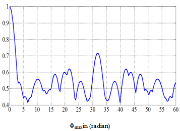 | Figure 4. Variation of normalized maximum for the 10-element array with the quadratic phase at edge of array Φmax |
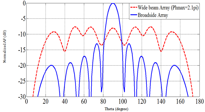 | Figure 5. The array factor of a 10- element array, separated by 0.5λ, for Φmax=2.1π , compared to that of the broad side array (Φmax=0) |
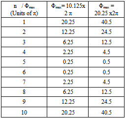
The arrangement of the proposed feed network is shown in Fig. 6. It can be shown that, (N/2-1) phase shifters are required for the N-element array to synthesize a wide beam pattern. For odd number of array elements, it can be shown that only (N-1)/2 phase shifters are needed. This is a considerable reduction in the number of phase shifters as compared to other phase-only techniques which needs N phase shifters[4,9,11]. For further investigation of the effect of the quadratic phase value Φmax, the maximum quadratic phase Φmax was varied between (0 – 46π) radian and the variation of the calculated -10 dB beam width with Φmax is shown in Fig. 7.This figure shows that the smallest beam width is obtained when Φmax=0, (broadside case). The beam width increases to higher values as Φmax is increased, then it starts to alternate between 78o and 153o values. As the value of Φmax was increased, the radiation in the main direction exhibits ripples as seen in Fig. 3. The peak to peak value of the ripples exceeded 10 dB for many values of Φmax. Therefore, the -10dB beam width was calculated as the angular separation between the outer-most -10dB points. In Fig. 7, the cases of radiation patterns having ripples swings larger that 10dB are marked by (*). Figure 7 also shows that at the three values of Φmax =[0, 20.25 π, 40.5 π] the beam width equals to the minimum of 17o. The two particular values (20.25 π, 40.5 π) of the quadratic phase yield patterns which share the same characteristics as that of the broadside case (Φmax=0).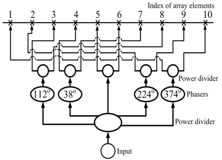 | Figure 6. The arrangement of the feed network when a quadratic phase excitations set is supplied to 10-elements array |
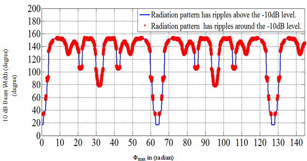 | Figure 7. The variation of the -10dB beam width of a 10- element array, separated by 0.5λ, for various quadratic phase values Φmax |
 | Figure 8. Variation of normalized maximum for the 10-element array with the quadratic phase at edge of array Φmax |
Table 1. The Phase Excitation Set for Φmax=2.1π, Before and After Subtracting the Smallest Phase Value
 |
| |
|
The reason is that due to the periodicity of the phase, the elements of the array have phases differing by multiple of 2π, ( or equivalently same phase) for these two particular cases of the array (N=10, d=λ/2). This is explained in the following:Using Eq4 and 5, the excitation phase Φn(zn) at the nth element of the array can be written as: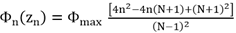 | (9) |
Substituting for the array length L= (N-1) d, the above relation reduces to: | (10) |
The term inside the square brackets has integer values, and it is odd for even number of elements N, but it is even for odd values of N. The other important factor is the phase difference ΔΦn between any two adjacent elements, (nth and (n+1)th elements), which can be found from Eq. 10 as: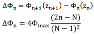 | (11) |
To obtain maximum radiation (broadside case), the phase difference ΔΦn should be multiple integer of 2π, so that all the elements will have the same phase. As (2n-N) is always an integer number, and it is even for even number of elements N, then the condition for broadside case requires that: | (12) |
Where M is an integer number. This implies that:  | (13) |
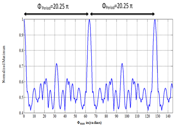
The relation (13) assumes even number of elements. For the investigated array, N=10, it can be shown that the first value of Φmax ( M=1) has to be 20.25 π, and the next value (M=2) has to be 40.5 π to yield broadside patterns. These results agree with the obtained results of beam width shown in Fig. 7. The excitation phase sets for these two cases are shown in Table 2.Figure 8 shows the variation of normalized maximum with the quadratic phase at edge of array Φmax. The value of normalized maximum alternates between 0.716 and 0.416 for all range of Φmax except for the Φmax around particular values  where the normalized maximum is equal to unity. The phase excitation sets (βn) for
 are shown in Table (2).
Table 2. The Quadratic Phase Excitation Set βn for Φmax=[20.25π, and 40.5π]
 |
| |
|
Comparing Figs. 7 and 8, it can be seen that when the maximum phase Φmax is changed over the range  radian, the beam width is at minimum values when the normalized maximum is at unity values. This explains the reciprocal relation between beam width and level of the main beam.
4. Effect of Varying the Number of Array Elements
The investigation of increasing the number of elements of the array for the two cases of; constant size and variable size of the array are presented in the following:In the first case the size of array is kept constant, while the number of elements N is increased leading to variable element spacing (d). The analysis considers the following example:A constant array size = 4.5 λ, and d=4.5 λ/(N-1). as this value was found to yield a pattern having smaller peak. N: was varied between (4 –19) elements. d: thus the resulting spacing between adjacent elements changed in the range (1.5λ – 0.25λ).The effect of increasing the number of elements on the normalized maximum is shown in Fig. 9. It is noticed that the normalized maximum decreases as the number of elements increases and settles to almost a constant value as the number of elements increases. As the maximum phase Φmax is increased the normalized maximum gets smaller, and settles to a constant value at higher number of elements as shown in Fig. 9.
 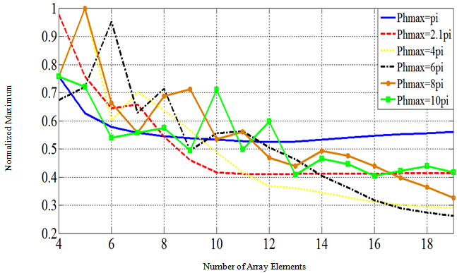 | Figure 9. Variation of the normalized maximum with the number of elements for a constant size array (4.5λ) using the shown values of maximum phase Φmax |
 | Figure 10. Variation of the normalized maximum with the number of elements for a constant element spacing (d=0.5λ) using the shown values of maximum phase Φmax |
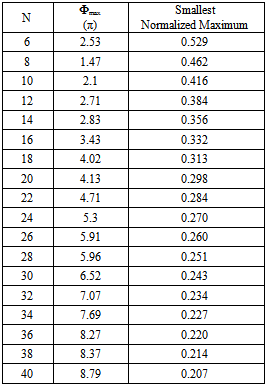
Table 3. The Smallest Values of the Normalized Maximum, and the Required Maximum Phase Φmax for Various Number of Array Elements
 |
| |
|
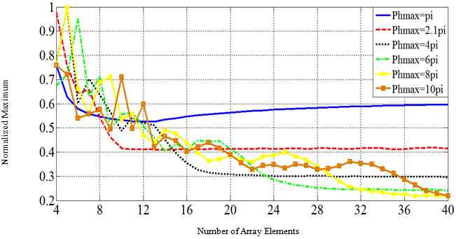
In the second case the spacing between adjacent elements was kept constant, the number of elements was increased, and thus the size of array was variable. The excitation phase which was given to each element of array was variable for each case, but the value of Φmax was kept constant. The normalized maximum of the array factor decreases as the number of elements increases as shown in Fig. 10. The normalized maximum approaches a constant value for larger number of elements. It can also be seen that as the maximum phase value Φmax is increased the normalized maximum settles to smaller values at larger number of elements.Table 3 summarizes the obtained results of the investigations considering the fixed element spacing of 0.5λ. The table shows that the maximum value of the radiated field can be reduced down to -7.62 dB for a 10-element array, and down to -13.6 for the 40-element array, in comparison with the conventional broadside array. The table can give useful design information.
5. Conclusions
While pencil beam antennas have found huge number of applications, and raised much interest, wide beam patterns are essential to many applications in various military and civil fields. In this paper a theoretical approach to the design of wide beam array antennas is investigated. The proposed technique employs phase-only excitations for the array elements. Uniform magnitude, and quadratic phase distribution is proposed for the element excitations, thus, the required number of phase shifters for an N-element array is (N/2-1), and (N-1)/2 for even, and odd number of elements N respectively. This is a considerable reduction in the number of phase shifters as compared to other phase-only techniques which needs N phase shifters. Moreover, the uniform magnitudes simples the feed network. The results of simulations of the proposed technique showed many-fold increase in the -10dB beam width as compared to the case for the broadside array. It has been also demonstrated that the maximum level of the radiated field can be reduced to -7.61dB for a 10-element array, and -13.6dB for the 40-element array relative to the conventional broadside case. The condition for obtaining broadside pattern even with the applied quadratic phase was derived. It is shown that this condition is periodic. The technique is useful for designing arrays that can distribute their radiation over wide range of angles.
References
| [1] | C. A. Balanis (Edit.), "Modern Antenna Handbook", (Wiley, 2008). |
| [2] | R. C. Hansen, “Phased array antennas”, Wiley and Sons, 2nd, 2009. |
| [3] | W. L. Stutzman, and G. A. Thiele," Antenna Theory and Design", 3th Ed., John Wiley & Sons, 2012, Chp. 8. |
| [4] | P. Burghignoli, F. Frezza, A. Galli, and G. Schettini, "Synthesis of Broad-Beam Patterns Through Leaky-Wave Antennas With Rectilinear Geometry", IEEE Antennas And Wireless Propagation Letters, Vol. 2, 2003, PP. 136-139. |
| [5] | R. L. Haupt, "Antenna Arrays: A Computational Approach", (Wiley, 2010). |
| [6] | Y. K. Alp, F. Altiparmak, G. Gok, A. Bayri, and A. Arikan," Two Different Approaches For Wide Beam Synthesis: Second Order Cone Programming And Swarm Intelligence", 20th Signal Processing Conference, EUSIPCO2012, 27-31 Aug. 2013, Romania, PP.1329-1333. |
| [7] | B. D. Stienberg,"Principles Of Aperture And Array System Design: Including Random And Adaptive Arrays", John Wiley & Sons Canada, Limited, 1976. |
| [8] | D. J. Thomson, "Spectrum Estimation and Harmonic Analysis", Proceedings of IEEE, Vol. 70, No. 9, Sept.1982, PP. 1055-1096. |
| [9] | S-M Lin, Y-Q Wang, and P-L Shen," Phase-Only Synthesis Of The Shaped Beam Patterns For The Satellite Planar Array Antenna", Proceedings of IEEE International Conference on Phased Array Systems and Technology, 2000, PP. 331-334. |
| [10] | M. Mouhamadou and P. Vaudon, "Smart antenna array patterns synthesis: null steering and multi-user beamforming by phase control", Progress In Electromagnetics Research, PIER 60, 95–106, 2006. |
| [11] | G. C. Brown, J.C. Kerce, and M.A. Mitchell," Extreme Beam Broadening using Phase Only Pattern Synthesis", 4th IEEE Workshop on Sensor Array and Multichannel, 2006, PP.36-39. |
 Abstract
 Reference
 Full-Text PDF
 Full-text HTML