N. N. Cvetkovic1, S. R. Aleksic1, A. S. Tatarenko2, R. V. Petrov2, M. I. Bichurin2
1Faculty of Electronic Engineering of Niš, University of Nis, Niš, 18000, Serbia
2Institute of Electronic and Information Systems, Novgorod State University, Veliky Novgorod, 173003, Russia
Correspondence to: R. V. Petrov, Institute of Electronic and Information Systems, Novgorod State University, Veliky Novgorod, 173003, Russia.
| Email: |  |
Copyright © 2012 Scientific & Academic Publishing. All Rights Reserved.
Abstract
Integral equation for electric field and potential in multilayer media is presented in this paper. Potential distribution function at the boundary surface is obtained as the solution of the integral equation. In some cases it is possible to obtain analytical solution of the equation. Such example is problem of a constant line charge parallel to dielectric cylinder having circular cross-section. Combining this solution with conformal mapping, the potential distribution at the surface of a square cross-section dielectric cylinder parallel to the line charge is determined. So-called sliding phenomenon, which is noticed in this case, is also described in the paper. In addition to that, approximate potential distribution at the boundary surface is determined in polynomial form, as the solution of above-mentioned integral equation.
Keywords:
Integral equation, Boundary surface potential, "Sliding" phenomenon
Cite this paper: N. N. Cvetkovic, S. R. Aleksic, A. S. Tatarenko, R. V. Petrov, M. I. Bichurin, Numerical Solving of Boundary Surface Potential Integral Equation and “Sliding” Problem, International Journal of Electromagnetics and Applications, Vol. 3 No. 5, 2013, pp. 121-126. doi: 10.5923/j.ijea.20130305.01.
1. Introduction
There are not many problems where electric field and potential distribution can be determined analytically, in closed form. Usually, it is possible to do so in analysis of the systems with certain symmetry features or the systems in which boundary surface completely or partially coincide with coordinate surface of used coordinate system. Generally, such problems are solved approximately, using appropriate numerical procedure. Usually, the integral equations with boundary surface charge distribution as unknown function are used. Integral equation analysed in the paper, has potential distribution at the boundary surface as unknown function. It is formed using Poisson's integral for circle[1-2] and boundary condition for normal component of electrical displacement at the boundary surface. In such a way, boundary conditions for tangential component of electric field and potential are automatically satisfied. Previously Poisson integral formula was revisited in[3].Exact analytical solution of the integral equation for system formed by constant line charge parallel to the dielectric cylinder having circular cross-section is used for approximate determining of potential distribution of the similar system, with the dielectric cylinder having square cross-section. Besides, Schwartz-Christoffel'stransformation is used[4, 5]. After mapping interior and exterior area of cylinder, the positions of the neighbouring interior and exterior point do not coincide, what presents "sliding" phenomenon.
2. Deriving Integral Equation
Integral equation for boundary surface potential is the result of the analysis carried out during determining Green's function for the potential in the system constituted of constant line charge placed parallel to the infinitely long dielectric domain of arbitrary-shaped cross-section (Fig. 1). The dielectric in above-mentioned domain is of permittivity ε1, while the system is placed in media of permittivity ε2. The potential distribution at the infinitely long domain surface is V(C).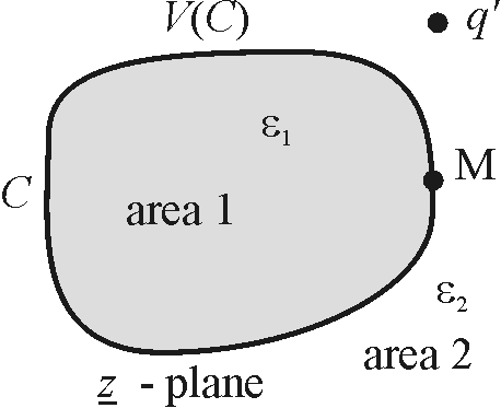 | Figure 1. Plan-parallel electrostatic system |
In order to derive integral equation for potential distribution at the boundary surface, two independent electrostatic systems are considered. They are formed using complex functions  and
and  , which map contour C from z -plane to the circle having radius A in w -plane. In that way, function
  maps interior area (1) of cylinder to the interior of the circle in
  -plane, and
  cylinder exterior area (2) to the exterior area of the circle in
  -plane, as it is presented in Fig. 2a-b.
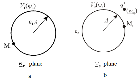 | Figure 2. Electrostatic systems formed using complex functions  and and  |
In general case, application of those complex functions, causes so-called "sliding" phenomenon. "Sliding" can be described in the following way: Let the point M, placed on the surface of the dielectric cylinder in z -plane, be mapped to the points Ms and Mu in  and
and  -plane, respectively. Both points, Ms and Mu are placed at the circle of radius A, but on different positions. This problem can be solved by analysing two independent electrostatic systems in w -plane. One is formed of constant line charge q′ placed in point
  parallel to the cylinder having circular cross section of radius A with V2(ψs) as potential distribution at the surface (Fig. 2a). Circular cross-section dielectric cylinder having radius A presents second system. Dielectric permittivity is ε and potential distribution at the surface is V1(ψu) (Fig. 2b). Since there is "sliding", i.e., the same point at the surface (with unique potential value) is mapped on different points using
  and
and  once can conclude V1(ψu)≠V2(ψs). Potential distribution in the systems presented in Fig. 2a-b, can be determined using well known Poisson's integral for the circle[1-2] as
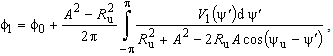 | (1) |
for system shown in Fig. 2a (potential at the points defined with  ) , and
 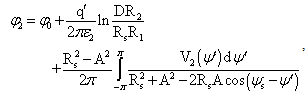 | (2) |
for system from Fig. 2b (potential at the points defined with  ). In expressions above the following is valid:
 ,
,  ,
,  ,
, 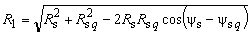 ,
,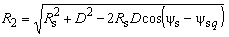 and
and  .Also, the constant
  value depends on the referent point choice and D parameter is obtained using quasistationary image theory for cylindrical perfectly conducting mirror. It is important to emphasize that expressions (1)-(2) represent the potential inside (1), i.e. outside (2) circularly-shaped cross-section boundary surface in Fig, but not at the surface. That distribution is V1(ψu), i.e.V2(ψs). In order to determine potential distribution in system presented in Fig. 1, it is necessary to express coordinates Ru, ψu (Fig. 2a) and Rs, ψs (Fig. 2b) using coordinates r and θ in -plane (Fig. 1). Boundary conditions for potential and tangential component of electric field are automatically satisfied at the cylinder surface, and boundary condition for normal component of electrical displacement is given as
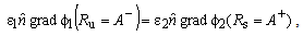 | (3) |
where  is normal ort on the boundary surface. In this way, it is possible to form integral equation having potential distribution at the boundary surface as unknown function.
3. Examples
3.1. Example 1
In the following text, procedure for deriving and solving (analytical and numerical) described integral equation is presented. That procedure is applied to the system formed by line charge q′ placed parallel to dielectric cylinder having circular cross-section of radius a. Distance between line charge and cylinder axis is labelled with d (d > a) and it is assumed that dielectric permittivity in cylinder is ε, as it is shown in Fig. 3. Cylindrical coordinate system with r, θ and z coordinates is placed so that z -axis coincides with cylinder axis. Line charge q′ is situated on direction defined with r = d, θ = 0. Now, taking in consideration (1) and (2), potential distribution can be expressed as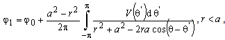 | (4) |
and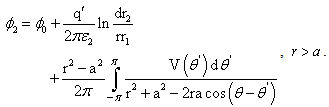 | (5) |
In expressions (4) and (5) the following is valid: and
and  .With V(θ) the function of potential distribution at boundary surface is labelled. Constant φ0 can be determined using condition that electric scalar potential at the axis is the same as in infinity φ (→0) = φ (→∞), and in that way is obtained,
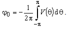 | (6) |
In this case is | (7) |
Applying expression (A5) from Appendix 1 (on (4) for  and on integral part in (5) for
  ) and expression (A7) on logarithmic part of (5), (4) and (5) are developed in Fourier's series. Now, potential can be expressed as
 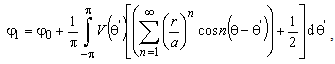 | (8) |
in interior, and 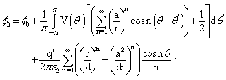 | (9) |
in the exterior of the cylinder. The expression (9) is Foureir's series of the expression (5) which has closed form and it will be applied at the boundary surface defined with  . The singularity for
  is the result of developing closed form (5) into series (it does not make problem in closed form (5)).Substituting two previously presented expressions and for r = a in (3), integral equation for potential distribution at electrode surface is obtained,
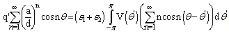 | (10) |
Solution of integral equation (10) is assumed as the sum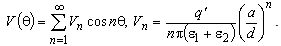 | (11) |
The coefficients  (11) are obtained after applying the solution of the integral
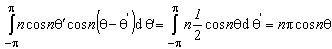 ,on integral in (10) and comparing left and right side of the expression (10). Using (A7), the solution for the potential distribution at the cylinder surface is expressed in the closed form,
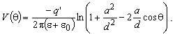 | (12) |
Function of potential distribution (12) is identical to the solution obtained by using image theorem in cylindrical mirror. Potential distribution at the surface of the cylinder presented in Fig. 3, is shown in Fig. 4 for d/a=1.5.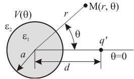 | Figure 3. Dielectric cylinder and line charge |
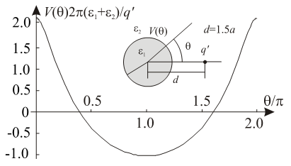 | Figure 4. Potential distribution at dielectric cylinder surface |
3.1.1. Approximate Determining of Potential Distribution
It is also possible to determine potential distribution numerically, where it is assumed that potential distribution has some other form. For example, for system presented in Fig. 3, potential distribution at the cylinder surface, (taking in consideration its symmetrical features), can be assumed in polynomial form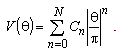 | (13) |
Besides, considering condition that value of the electric field tangential component at the surface point defined with θ = 0 is zero, it is obtained that C1 = 0. The same condition for point defined with r = a, θ = π results with the following equation | (14) |
In order to explain procedure for numerical determining of coefficients Cn, n = 0,1,2,...N, potential distribution (13) will be expressed as 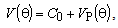 | (15) |
Where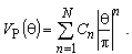 | (16) |
The value of coefficient C0 = V (θ = 0) depends on the referent point choice. It can be calculated from condition (7) using expression (6), after determining coefficients Cn, n = 1,2,...N. Calculation of those coefficients is based on the procedure described in the following text.After substituting (16) in expression (10), carrying out some simple mathematical transformations and using C1 = 0, it is obtained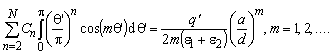 | (17) |
Since there are N − 1 unknown coefficients (Cn, n = 2,...N), system of linear equations constituted from equation (14) and total N − 2 equations given with (17) (m =1,...N − 2), as solution gives coefficient values Cn, n = 2,...N.Exact and approximate potential distributions on upper half of dielectric cylinder surface for different degree of approximation (13) and d = 1.5a are presented in Fig. 5. For degree higher than 5, approximate distribution is very close to exact solution.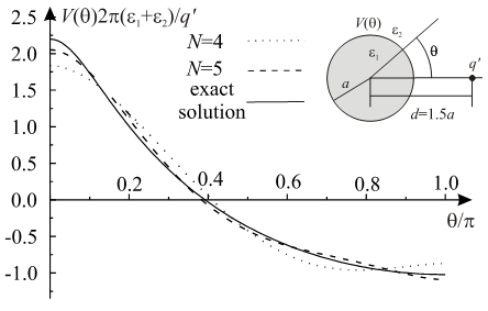 | Figure 5. Potential distribution |
Absolute value of relative error 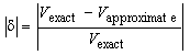 in determining potential distribution at upper half of cylinder surface is presented in Fig. 6. Analysing Fig. 5 and 6, it can be noticed that error has maximum in the vicinity of the surface point where potential value is 0. That error maximum is local, and exists on very narrow part of electrode surface.
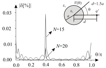 | Figure 6. Absolute value of relative error of approximate potential distribution |
3.2. Example 2
The square cross-section dielectric rod, having side  is analysed. Dielectric permittivity of he rod is
  and line charge
  is placed near the rod, on direction
  (
( ),
), (Fig. 7). The permitivitty of surrounding media is ε2.
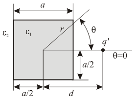 | Figure 7. Dielectric rod and line charge |
The potential of the system can be expressed as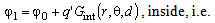 | (18) |
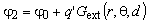 | (19) |
In (18)-(19),  labels Green function for the electric scalar potential of the line charge from Fig. 7 inside rod, while
  is the corresponding Green function outside the rod. Constant φ0 can be determined using condition that electric scalar potential at the axis is the same as in infinity φ (→0) = φ (→∞). Since there are not any appropriate Green functions, the problem has been solved applying approach which includes complex function.Using Schwartz-Christoffel's transformations
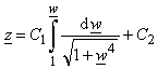 | (20) |
and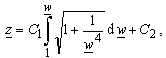 | (21) |
rod interior is mapped to interior of unit circle (function (20)), and exterior area of rod is mapped to unit circle exterior (function (21)) in  -plane[7]. In this way, problem from
  -plane is reduced to analysis of the system presented in Example 1. Obviously, complex functions (20) and (21) correspond to the functions
  and
and  introduced in second chapter of this paper, respectively. As it has been already explained, to determine potential distribution in the system presented in Fig. 7, it is necessary to express complex coordinate
  using radial coordinates r and θ in
  -plane. In this case, for complex function (20) and (21), that is possible to carry out this numerically. Among others, there is procedure based on iterative process, proposed in[7]. For mapping point defined with
  from exterior of square cross section rod, corresponding value of complex coordinate
  in
in  -plane is obtained from iterative procedure as
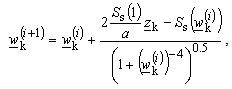 | (22) |
where  , and (i) is label for iteration number. In similar way, it is possible to derive iterative procedure for mapping interior of the rod (
 -plane) from Fig. 7 to unit circle interior (
 -plane),
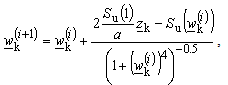 | (23) |
where 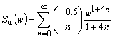 .Convergence of described iteration procedures (22) and (23) depends on appropriate choice of starting value
  . For largest part of space, described procedures are convergent if starting values are chosen as
 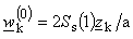 (procedure (20)), and
 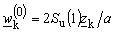 (procedure (23)). In areas where those start values do not provide convergence, it is necessary to chose start values using some other criteria. It can be "searched" for starting solutions in area where they are expected to be found. In this case, for boundary surface, the facts that square cross-section is mapped to unit circle and that corresponding points in
  -plane are known for the square edge in
  -plane, are used. So, it is possible to reduce complex function to real function of one argument. Then, numerical value of inverse function can be determined and used as starting value that provide convergence of iterative procedures (23) and (23). In this case, in previous text described "sliding" phenomenon can be noticed. It is illustrated in Fig. 8. The surface points placed between A and B on the rod are not mapped to the same points on unit circle using complex functions (20) and (21). Mappings (20) and (21) map points A and B to the same points. That could be expected, concerning existing symmetry and cross-section geometry.
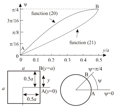 | Figure 8. "Sliding" |
Potential distribution at the rod surface (Fig. 7), using analytical solution (12) for system from Fig. 3 and complex functions (20) and (21) for d = a, is presented in Fig. 9. Because of "sliding", for different complex functions, different potential distributions are obtained.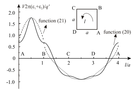 | Figure 9. Potential distribution |
In Figs. 10 and 11 approximate potential distributions are presented, when above described procedure for approximate determining of potential distribution in polynomial form is used. The approximate distributions are compared with functions obtained using exact solution (12), when complex functions (20) and (21) are applied. The degree of approximation (13) is  .
.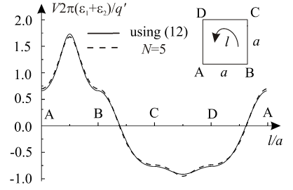 | Figure 10. Approximate potential distribution when complex function (20) is used |
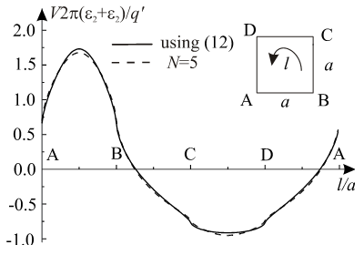 | Figure 11. Approximate potential distribution when complex function (21) is used |
4. Conclusions
Integral equation for electric field and potential in multilayer media is presented in this paper. Solution of the integral equation is potential distribution at the boundary surface. Analytical solution of the equation can be obtained in some cases, as it is the problem of constant line charge parallel to the dielectric cylinder having circular cross-section. Using this solution in combination with conformal mapping, the potential distribution at the surface of square cross-section dielectric cylinder near parallel line charge is determined. Besides, the so-called "sliding" phenomenon is described. The procedure for approximate determining of potential distribution at the boundary surface is also presented. Potential distribution function is approximately determined in polynomial form. This procedure can be used in the solution for the transmission line with non-uniform or magnetoelectric filling[8] and will applied for the calculation of complex microwave devices.
ACKNOWLEDGEMENTS
The reported study was partially supported by the grant of the Federal Target Program “Scientific and pedagogical staff of innovative Russia” on 2009-2013 and by RFBR research project #13-02-98801.
Appendix 1
The sum of complex geometric series is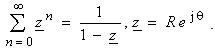 | (A1) |
Real part of previous expression has the form | (A2) |
 | (A3) |
Consenquently is | (A4) |
 | (A5) |
Appendix 2
Integrating expression(A1) obtaines | (A6) |
where is  .Real part of previous expression has the form
 | (A7) |
References
| [1] | A. Arwin, “The Poisson Integral and an Analytic Function on Its Circle of Convergence”, Annals of Mathematics , Second Series, Vol. 23, No. 2 (Dec., 1921), pp. 141-143. Available at: http://www.jstor.org/stable/1968029 |
| [2] | O.V. Tozoni, "Mathematical Models for Calculation of Electrical and Magnetic Fields", Edited Machine Translation of "Mathematicheskiye modeli dlya rascheta elektricheskikh i magnitnykh poley", Akademiya Nauk Ukrainskoy SSR Institut Kibernetiki (in Russian), Air Force System Command, Foreign Technology Division, 1968, pp. 27, Avaliable at: http://www.dtic.mil/cgi-bin/GetTRDoc?AD=AD0670961 |
| [3] | J. T. Chen and C. S.Wu, "Alternative derivations for the Poisson integral formula", International Journal of Mathematical Education in Science and Technology, Vol. 37, No. 2, 2006, 165-185. |
| [4] | E. B. Christoffel, “Sui Problema delle Temperature Stazionarie e la Rappresentazione di una Data Superficie”, Ann. Mat. Pura Appl., 1, 1867, p.p. 95. |
| [5] | H. A. Shwartz, “Über einige Abbildungsaufgaben”, J. Reine Angew, Math.,70, 1869, p.p. 105. |
| [6] | N. B. Raičević, S. R. Aleksić, S. S. Ilić, “Hybrid Boundary Element Method for Multi-layer Electrostatic and Magnetostatic Problems”, Electromagnetics, Taylor & Francis, Vol. 30, No.6, pp. 507-524, 2010. DOI:10.1080/02726343.2010.499067. |
| [7] | J. V. Surutka, D. M. Veličković, "Some Improvements of the Charge Simulation Method for Computing Electrostatic Fields", Bulletin LXXXIV de l´ Academie Serbe des Sciences et des Arts, Class des Sciences techniques, No 15, p.p. 31-35, 1981. |
| [8] | M.I. Bichurin, R.V. Petrov, V.M. Petrov, F.I. Bukashev, A.Yu. Smirnov. Electrodynamic analysys of strip line on magnetoelectric substrate. Proc. of IV Conf. On Magnetoelectric Internation Phenomena In Crystals (MEIPIC-4), Ferroelectrics, 2002, V. 280, p.203. |
 Abstract
 Reference
 Full-Text PDF
 Full-text HTML