R. A. Khudan, J. S. Aziz
Department of Electronic and Communications Engineering, College of Engineering, Alnahrian University, Baghdad, Iraq
Correspondence to: J. S. Aziz, Department of Electronic and Communications Engineering, College of Engineering, Alnahrian University, Baghdad, Iraq.
| Email: |  |
Copyright © 2012 Scientific & Academic Publishing. All Rights Reserved.
Abstract
The present work introduces an automated optimization-based methodology for miniaturizing the size of a Fractal Planar Inverted-F Antenna (FPIFA) that can be used for Wireless Sensor Network applications. The methodology uses particle swarm optimization (PSO) algorithm. It was applied to the first four fractal (0th- 3rd) orders of FPIFA antenna. The optimization results reveal 68% reduction in area for the 3rd-order fractal PIFA antenna compared to the reference PIFA antenna. The third order miniaturized FPIFA has an overall size of (72.3 × 49.67 × 9.6) mm³ (i.e., λ/9.6 × λ/14 × λ/72, where λ is the free-space wavelength at 434 MHz). The PIFA antenna design is modified by reducing the substrate layer (by eliminating the foam material from the substrate layer). The optimization methodology is also applied to the first four Minkowski island fractal orders of the modified PIFA antenna (FMPIFA). A maximum reduction in area for the third FMPIFA antenna achieved was 86.5% compared to the RPIFA antenna. The 3rd-order fractal antenna has an overall size of (59.66 × 25.96 × 1.5) mm³ (i.e., λ/11.6 × λ/26.6 × λ/461) with an obtained volume reduction of more than 98% compared to the RPIFA antenna. Some of these models have been implemented practically. The practical and simulation results comparison shows a small frequency discrepancy.
Keywords:
PIFA, Minkowski Fractal Geometry, PSO Optimization, WSN
Cite this paper: R. A. Khudan, J. S. Aziz, Design and Implementation of Miniaturized Antennas for Wireless Sensor Network Applications Using Particle Swarm Optimization, International Journal of Electromagnetics and Applications, Vol. 3 No. 4, 2013, pp. 81-95. doi: 10.5923/j.ijea.20130304.04.
1. Introduction
Advances in nanotechnology and Micro Electro - Mechanical Systems (MEMS) increased the interest in low-bitrate Wireless Sensor Network (WSN), which is simply a network of a large number of small sensing self - powered nodes that are capable of gathering information of a physical phenomenon and communicating in wireless fashion[1]. Sensing, processing and communicating are combined in one tiny device that is involved in a vast number of applications[2].Correct choice of antenna will improve system performance and reduce the cost. A compromise between antenna size, cost and performance needs to be found. Typically for a Wireless Sensor system it is desirable to have an Omni-directional radiation pattern such that the performance will be approximately the same regardless of the position of the transmitter and receiver. For directional antenna these units must be known in detail. By reducing the operating frequency by a factor of two, the effective range is doubled. Thus one of the reasons for choosing to operate at a low frequency when designing an RF application is often the need for long range[3]. Additionally, the available equipments at this frequency are now smaller and cheaper[4]. However, most antennas at low frequencies are large in size, for this circumstance, printed planar inverted-F antennas are a very attractive choice because of their well-known advantages of low profile, light weight, low cost, easy fabrication, and good radiation characteristics[5]. Fractal geometry, because of its geometrical properties; can be used for designing a small scaled antenna[6, 7]. Also an automation technique is usedto miniaturize the size of the antenna using particle swarm optimization (PSO) algorithm [8]. In this paper, PSO, implemented in MATLAB, is used in along with CST Microwave Studio (CST MWS), which is an electromagnetic simulator based on Finite Integral Technique (FIT)[9], to introduce a new design methodology for miniaturizing fractal PIFA antenna.
2. Related Work
Several antennas have been proposed for WSN applications that operate at ISM 433 MHz band[4, 10, and 11]. In 2008 Phaebua et al[4] proposed two rectangular printed spiral antennas with U-strip. The measured return loss is -12.435 dB at 433 MHz with 5.455 % bandwidth. The measured absolute gain is about -5 dBi. The performance of the proposed antenna is efficient for wireless applications especially wireless sensor networks of ITS.In 2011, Liu et al[10] presented a novel and compact antenna for ISM 433 MHz frequency band that can be used for low date rate applications, such as WSN and remote controls. In 2012, Liu, Zhang, and Feng[11] designed a miniaturized monopole antenna using the shielding box of mobile terminals for wireless applications at ISM 433 MHz frequency band.
3. Miniaturization Methodology for FPIFA AntennaStyle
Recently methods of global optimization like the particle swarm optimization (PSO) were introduced to the electromagnetic (EM) community to find optimal solutions for a complex electromagnetic problem[8]. The EM package used for modelling and performance evaluation of the proposed antennas is the Computer Simulation Technology (CST) MICROWAVE STUDIO TM software package (ver.2010), which has been proven to be very efficient in both speed and accuracy of computations. This simulator utilizes the Finite Integral Technique (FIT) for computing the electromagnetic properties.The optimization process is implemented shown in Fig. 1. The two software programs MATLAB and CST MWS are linked using TEXT files as a temporary memory file. The particle swarm optimization (PSO) is a robust stochastic evolutionary computation technique was originated by imitating the movement and intelligence of a swarm of bees, a flock of birds or a school of fish during their food-searching activities.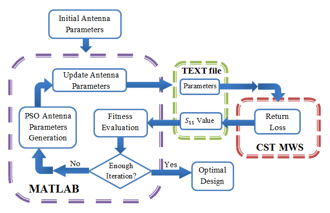 | Figure 1. MATLAB-CST linking explains the flowchart of the PSO-FIT algorithm |
The challenge is to determine the geometric parameters of PIFA antenna; such as the patch dimensions, fractal scaling factors, feed position, and shorting pin position; to achieve the best design that satisfies a certain criterion. To evaluate the fitness function of the antenna an EM package has been used at each stage of optimization combined with MATLAB software where the PSO kernel is implemented.
3.1. FPIFA Geometry
A conventional Planar Inverted-F Antenna is designed as a reference antenna (RPIFA) at 434 MHz operating frequency. Its configuration consists of:• radiating patch with dimensions W×L• ground plane with dimensions  • high thickness (H) substrate layer mediates between the patch and the ground planes (in this work H composed of two dielectric materials, the FR4 with
  = 1.6mm thickness and
  = 4.3, andthe foam dielectric material with
  = 8 mm thickness and
  = 1.07 ).• shorting pin• feeding pinThe shorting pin and the feeding pin connect the radiating plate with the ground plane at proper positions (
 ) and
) and  from the center of the patch, respectively (see Fig. 2). The dimensions of the ground plane
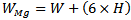
  dependent to the dimensions of the radiating patch L and W that is:
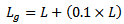 | (1a) |
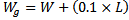 | (1b) |
 | Figure 2. Planar Inverted-F Antenna Geometry |
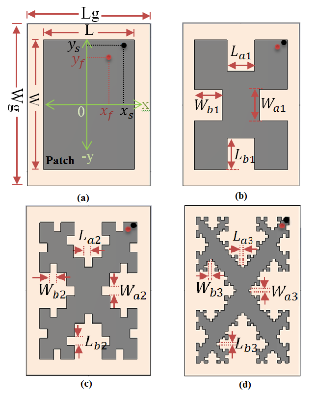 | Figure 3. Scheme of the Minkowski fractal PIFA antenna orders structure. (a) FPIFA0. (b) FPIFA1. (c) FPIFA2. (d) FPIFA3 |
Minkowskifractalizationhas been implemented to the RPIFA antenna. Fig. 3 shows the geometry of the iterative generation of Minkowski island fractal and illustrates design geometrical parameters.The first step for implementing the PSO algorithm is to select the parameters to be optimized and giving them a reasonable searching range for each parameter called the solution space. The number of the selected parameters is denoted by (N).In this work, six of the common parameters (seeFig. 3 (a)) are considered in the optimization process. Patch length L and width W represent the main parameters, and the other parameters are represented by scaling factors from the main ones. This is useful to ensure that physically invalid structures are not constructed and consequently prevent total failure of the optimization process.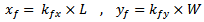 | (2a) |
 | (2b) |
where  are the scaling factors used for the feeding point and
  are the scaling factors for the shorting pin. For symmetry reasons, when searching the position forshorting and feeding pins only a quarter of the domain is depicted.The iteration factors, for the fractal antennas (FPIFA1, FPIFA2, and FPIFA3), are subjected to additional structure parameters (see Fig. 3). Two scaling factors are introduced here for any fractal order to decrease the time needed for the computation and limit the number of optimization parameters. These two scaling factors are
  and
and  , defined as follows, where
  represents the desired Minkowski fractal-order:
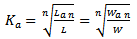 | (3a) |
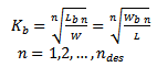 | (3b) |
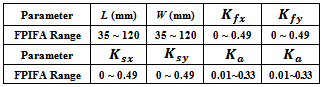
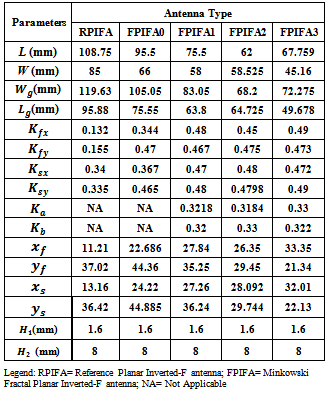
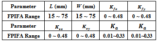
Table 1 lists the ranges of the geometrical parameters entering the optimization process. It shows the ranges for the designed FPIFA antennas. These ranges are taken for all the fractal orders.Table 1. Ranges of the design Parameters for the miniaturized FPIFA antennas
 |
| |
|
The PSO optimization is initiated by randomly allocating particle positions in the solution space (see Fig. 1). The particle position represents the geometrical parameters of FPIFA antenna. A reasonably large number of PSO iterations are also necessary for the particles to get converged. In this work, the number of particles used is chosen to be 4𝑁 for 60 PSO iterations to provide a better sampling of the solution space. A 24-particle-swarm is used for FPIFA0 antenna; since it has six geometrical parameters associated with the optimization process, and a 32-particle-swarm for antennas FPIFA1, FPIFA2 and FPIFA3 since they have eight geometrical parameters.
3.2. PSO Fitness Function
The goal is to minimize the size of FPIFA by altering the geometrical parameters within allowed prescribed ranges while keeping the return loss below a desired threshold value  at resonant frequency
  . For WSN applications the resonant frequency is chosen to be 434 MHz.The optimization fitness function consists of two objective functions which are related to antenna return loss and antenna area[8] where
  denotes the return loss objective function,
 | (4a) |
 | (4b) |
It represents the amount of input impedance matching at the desired frequency  . It ranges between "0" and
  . Its zero value indicates that the matching goal is achieved.While
  denotes the area objective function; it is used to achieve a minimum area from the optimization process:
 | (4c) |
The range of  is between "0" and "1". If the area of nth order fractal antenna equals the area of the reference design (no miniaturization),
  is "1". It goes toward zero when the area of the nth-order fractal antenna is miniaturized and reaches zero when the area equals zero (physically not allowed). The area miniaturization goal is achieved by selecting the minimum decimal fraction between zero and "1".The overall fitness function becomes:
 | (5a) |
Subjecting to: | (5b) |
 | (5c) |
and the constraints: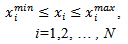 | (5d) |
where: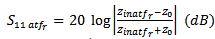 | (5e) |
In the previous equations,  refers to the Heaviside step function while
  and
and  denote the area of the nth-order fractal, the reference PIFA, and the optimized
  order fractal antennas respectively.
  , and
, and  represent the minimum and the maximum range available for i parameter. In eqn. (5 e),
  and
and  refer to the return loss and the input impedance of the antenna at the resonance frequency
  respectively, and
  is the characteristic impedance (
 =50 Ω).The value of the total fitness function
  which is considered as multi-objective optimization problem ranges between a minimum value of zero and a maximum value of
  .The fitness function also subjects to other constraints and to FPIFA design boundary conditions that will be explained later.The antenna size miniaturization percentage (RA%) can be calculated using:
 | (6a) |
 | (6b) |
3.3. FPIFA Design Constraints and Boundary Condition
When PSO searches the domain for feeding pin and shorting pin positions that give the optimum antenna design, some limitations arise from the fact that the feeding pin and the shorting pin may not have the same position and that the distance between them must be at least 1mm (which equals the diameter of the shorting pin  , therefore
  and
and  parameters must subject to the following condition that is applied to all FPIFA fractal orders:If
  , Then,
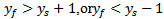 | (7) |
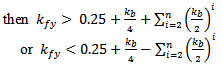
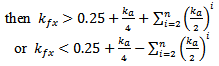
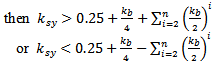
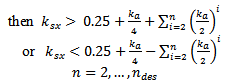
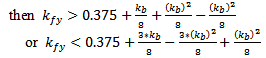
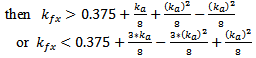
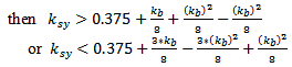
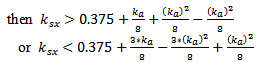
To avoid fallacious design for fractal antennas (FPIFA1 – FPIFA3) caused by placing the shorting pin or the feeding pin in a patch slot induced by fractalization. The following conditions must hold as additional geometrical restrictions for  and
and  parameters:If
 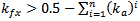 then
then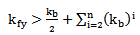 | (8a) |
If 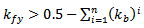 then
then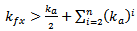 | (8b) |
If 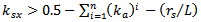 then
then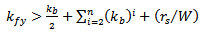 | (8c) |
If 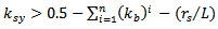 then
then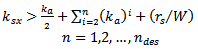 | (8d) |
For the second and the third orders of Minkowski fractal PIFA antenna, more constraints are needed for the slots at quarter length of L and W (see Fig. 3).If 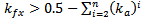
 | (9a) |
If 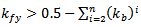
 | (9b) |
If 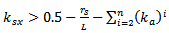
 | (9c) |
If 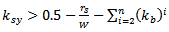
 | (9d) |
For the third order Minkowski island fractal (n=3) there are two more conditions for the small slots at the corners of the design.If 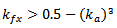
 | (10a) |
If 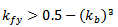
 | (10b) |
If 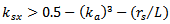
 | (10c) |
If 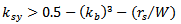
 | (10d) |
If the feeding pin position or shorting pin position of any particle exceeds these limitations, one of the three PSO control approaches can be used (which are the absorbing walls, the reflecting walls, and the visible walls[12]). For the constraints given in eqns. (7-10), the absorbing walls technique is used to pull back the particle toward the allowed solution space. On the other hand the constraints given in eqn. (5), the reflecting walls technique is used to reflect the particle back toward the solution space.
4. Optimization and Simulation Results for FPIFA Antenna
As expected, the parallel PSO-FIT algorithm optimizes the return loss of FPIFA antennas at 434 MHz resonant frequencies and improves the antenna size reduction compared to the size of the reference design. For each FPIFA order and through the 60 iterations, the PSO tries to find the minimum size for the design that has  below the threshold value given in the fitness function. For the FPIFA antennas, the threshold value
  was taken to be (-25dB). Two criteria are used to describe the convergence performance. The first criterion marks the best value of the total fitness function up to the current iteration (
 up to the current iteration). The second criterion marks the best fitness function at each PSO iteration and illustrates the instantaneous variation in the fitness function during the optimization process (
 at the current iteration).Fig. 4 shows the convergence optimization results of the four fractal orders for the optimized FPIFA antenna. The best
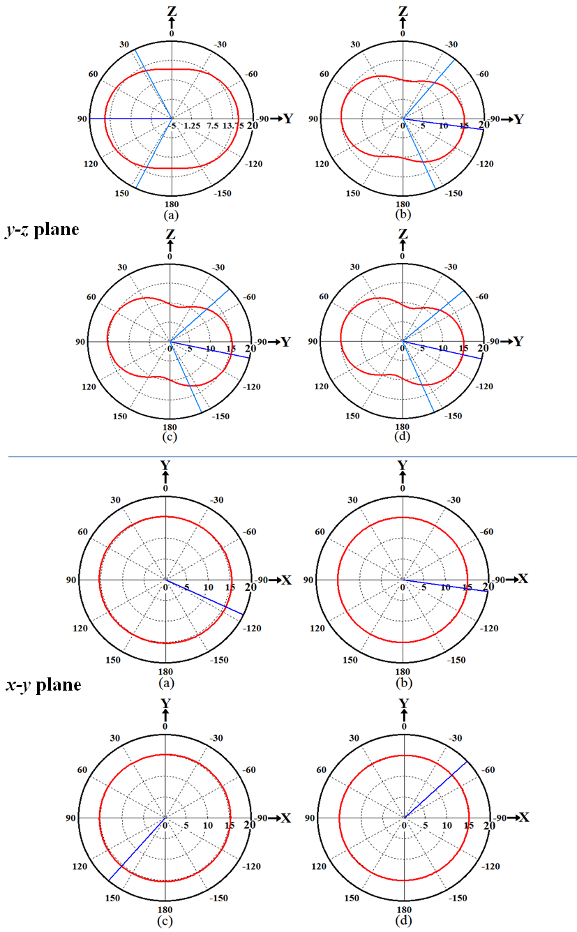
  up to the current iteration fitness value for FPIFAs; which gives the required solution, appears at the 38th, 29th, 17th, and 10th iterations for FPIFA 0th-, 1st-, 2nd-, and 3rd- fractal orders respectively.The optimum results created by the PSO algorithm summarized in Table 2 represent the geometrical parameters for the FPIFA antennas that give the minimum fitness value. Minimum fitness value means that the designed FPIFA antennas have the smallest designs and satisfy the return loss threshold value after only 60 PSO iterations.The antenna size miniaturization and the total ground area are listed in Table 3 to demonstrate the PSO optimization achievements. Antenna size miniaturization is the precents of the reduced area and can be calculated using (eqn. 6).The electromagnetic performance of the optimized antennas is simulated using the electromagnetic CST MWS simulator. The return loss characteristics for the optimized MinkowskiFPIFA antennas are shown in Fig. 5. The return loss for the RPIFA antenna is also shown for the purpose of comparison. The radiation characteristics of the optimized antennas are also simulated at 434 MHz frequency. In Fig. 6 the 3D linear radiation patterns are plotted for zero-, 1st-, 2nd-, and 3rd- order Minkowski fractal PIFA antennas.Fig. 7 shows the radiation patterns in the vertical plane y-z (ϕ=90°) and x-z (ϕ=0°) planes and horizontal plane x-y (θ=90°) plane for the optimized FPIFA antennas at 434 MHz. From Figs. 6 and 7, it appears that antenna radiates the component in a nearly Omni-directional radiation pattern. Therefore the optimized antennas achieve the requirements needed for WSN applications.
Table 2. The Geometrical Parameters of the optimized FPIFA antennas
 |
| |
|
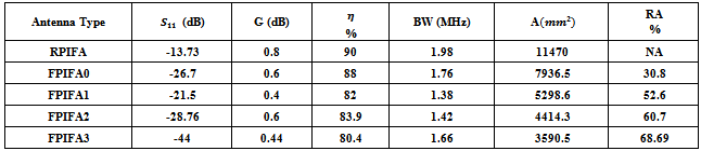
Table 3. Simulation results of FPIFA antennas at 434 MHz operating frequency
 |
| |
|
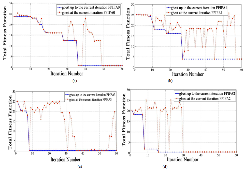 | Figure 4. PSO behaviors for the FPIFA antennas (a) 0th- order (b) 1st-order (c) 2nd- order (d) 3rd- Minkowski fractal order. |
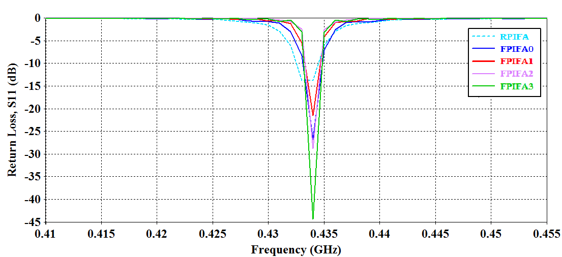 | Figure 5. The return loss curves for the optimized FPIFA antennas |
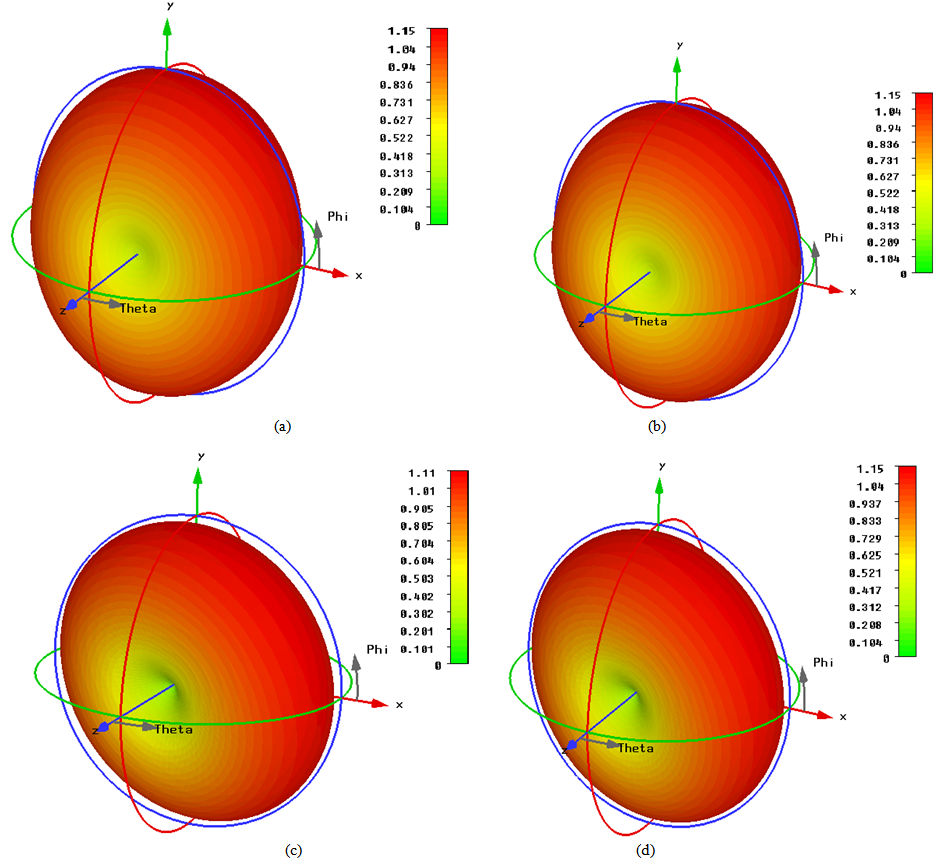 | Figure 6. Computed 3D linear radiation patterns of the optimized FPIFA antennas. (a) Zero- order (b) First- order (c) Second- order (d) Third- order Minkowski island fractal |
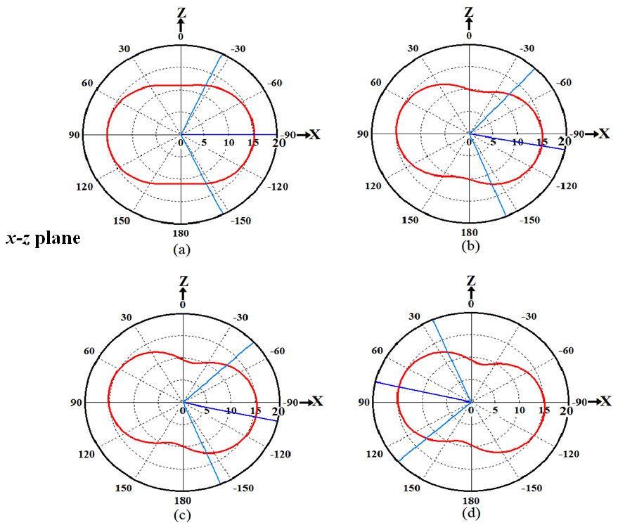 | Figure 7. Simulated 2D Radiation Patterns for the optimized FPIFA antennas. (a) Zero order. (b) 1st order. (c) 2nd order (d) 3rd order fractal |
 | Figure 7. Simulated 2D Radiation Patterns for the optimized FPIFA antennas. (a) Zero order. (b) 1st order. (c) 2nd order (d) 3rd order fractal |
5. FPIFA Implementation and Measurements Results
PIFA antenna fabrication is a big challenge, particularly the design of the Fractal Planar Inverted-F Antenna (FPIFA). Its performance is very sensitive to the dimension changes where any shift in the fabrication will shift the resonant frequency and hugely affect the input impedance. The optimized 0th-, and the 3rd- Minkowski fractal FPIFA antennas are implemented using LPKF ProtoMat S100 rapid PCB prototyping machine[13]. The photographs of the fabricated FPIFA antenna prototypes are shown in Fig. 8.After the construction, the return loss characteristics measurement was performed for both of the fabricated FPIFA antennas using Vector Network Analyser (VNA- MS4642A)[14]. Figs. 9 (a), and (b) show the comparison between the practical and the measured return loss values for the optimized FPIFA0, and FPIFA3, respectively.The discrepancies of the frequency behaviors between the measured and simulated results are certainly due to small changes in the FR4 and foam thicknesses and the unpredictable variation in the dielectric constant of the substrate material due to the glue used for pasting PIFA’s constructing layers.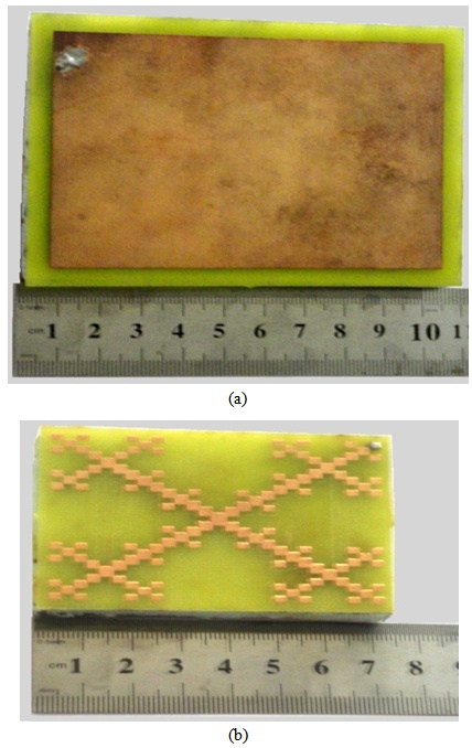 | Figure 8. The prototype optimized FPIFA antennas with supporting foam material. (a) The optimized FPIFA0. (b) The optimized FPIFA3 |
Nevertheless, the resonance measured has a slight frequency shift compared to the simulated one. The obtained resonant frequency is 434 MHz for the both FPIFA0 and FPIFA3 simulated antennas. Whereas it is 420 MHz for the FPIFA0 and 422 MHZ for the FPIFA3 measured antennas.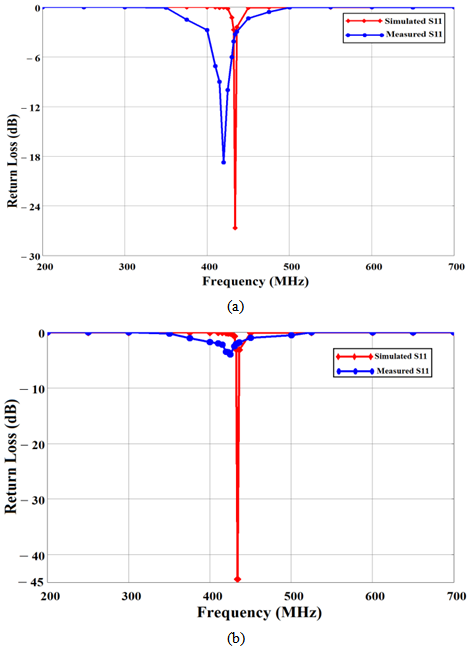 | Figure 9. The measured and simulated return loss values (a) optimized FPIFA0 antenna (b) optimized FPIFA3 antenna |
6. Modified PIFA Antenna
For further reducing the size of the antenna the conventional reference PIFA was modified. In this proposed design the substrate is composed of a single thin dielectric layer. Antenna volume decreases by removing the 8mm foam and keeping the 1.5mm FR4 substrate layer  . The modified PIFA model is designed using eqn. (11).
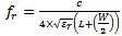 | (11) |
The radiating patch is printed on one side of FR4 substrate material. The ground is printed on the other side of the FR4 substrate layer. The dimensions of the grounded substrate  and
and  are dependent on the dimensions of the radiating patch L and W and the thickness of the substrateH that is:
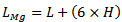 | (12a) |
 | (12b) |
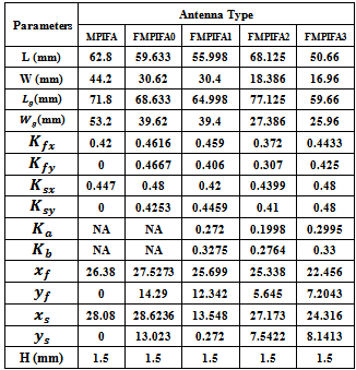
MinkowskiFractalization for MPIFA antenna has proceeded from zero to the third fractal order. Optimization process has been carried out to obtain miniaturized antenna size and good input impedance matching for the four orders of the Minkowski fractured modified PIFA antenna (FMPIFA). Table 4 lists the ranges of the geometrical parameters entering the optimization process for the designed FMPIFA antennas. These ranges are taken for all the fractal orders.Table 4. Ranges of the design Parameters for the miniaturized FMPIFA antennas
 |
| |
|
The number of particles used for FMPIFAs is chosen to be  for 60 PSO iterations to provide a better sampling of the solution space. A 24-particle-swarm is used for FPIFA0 antenna; since it has six geometrical parameters associated with the optimization process, and a 32- particle swarm for antennas FPIFA1, FPIFA2 and FPIFA3 since they have eight geometrical parameters. Area reduction has been calculated for all the optimized fractured modified Planar Inverted-F antenna (FMPIFA) antennas using eqn. 6 in which
  represents the area of the ground plate for the n fractal order of FMPIFA antennas and
  represents the area of the ground plate for the Reference antenna before modification, fractalization and optimization.The optimization fitness function and design constraints and boundary conditions used for FMPIFA antennas are the same as that used for FPIFA antennas (see eqns. 4 -10) one difference is that the threshold value
  taken for FMPIFA antennas was (-17 dB).Antenna volume miniaturization is the main objective for designing the MPIFA. Volume miniaturization percent can be calculated by,
 | (13) |
where  equals
  and represents the volume of the low profile modified antenna from the zero to the third fractal order. The
  equals
  and represents the volume of the RPIFA antenna.
7. Optimization Results of FMPIFA Antennas
The PSO algorithm has been used to optimize the FMPIFA designs. The PSO tries to make the FMPIFA antennas have a return loss  at 434 MHz resonant frequencies below the threshold value given in the fitness function and improves antenna size reduction compared to the size of the reference design RPIFA through 60 PSO iterations.Fig.10 shows the convergence optimization results of the four fractal orders for the optimized FMPIFA antenna. The best
  up to the current iterationfitness value for FMPIFAs; which gives the required solution, appears at the 43th, 24th, 51th, and 37th iteration for 0th-, 1st-, 2nd-, and 3rd- fractal order respectively.The functionality of the design methodology for miniaturizing each FMPIFA antenna is proven to be efficient, since the optimum layout suggested by the PSO algorithm places the shorting pin at the corner of the patch.The optimum results created by the PSO algorithm represent the geometrical parameters for the FMPIFA antennas that give the minimum fitness value. Minimum fitness value means that the designed FMPIFA antennas (from 0 – 3rd fractal order) have the smallest designs and satisfy the return loss threshold value after only 60 PSO iterations.Table 5 summarizes the optimized parameters and illustrates the geometrical dimensions of the optimized antenna.The electromagnetic performance results of the optimized FMPIFA antennas are obtained from the electromagnetic simulator CST. Fig. 11 shows the return loss characteristics for the optimized FMPIFA antennas it also includes the return loss for the MPIFA antenna for comparison purposes. Figs. 12 and 13 show the 3D linear radiation pattern and the 2D radiation patterns for the optimized FMPIFA antennas from 0th – 3rd fractal order, respectively at 434 MHz resonance frequency.
Table 5. The Geometrical Parameters of the optimized FMPIFA antennas
 |
| |
|
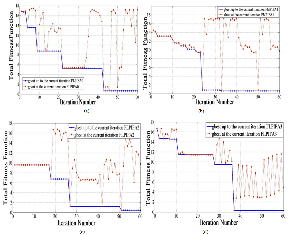 | Figure 10. PSO behaviors for the FLPIFA antennas (a) 0th- order (b) 1st-order (c) 2nd- order (d) 3rd- Minkowski fractal order |
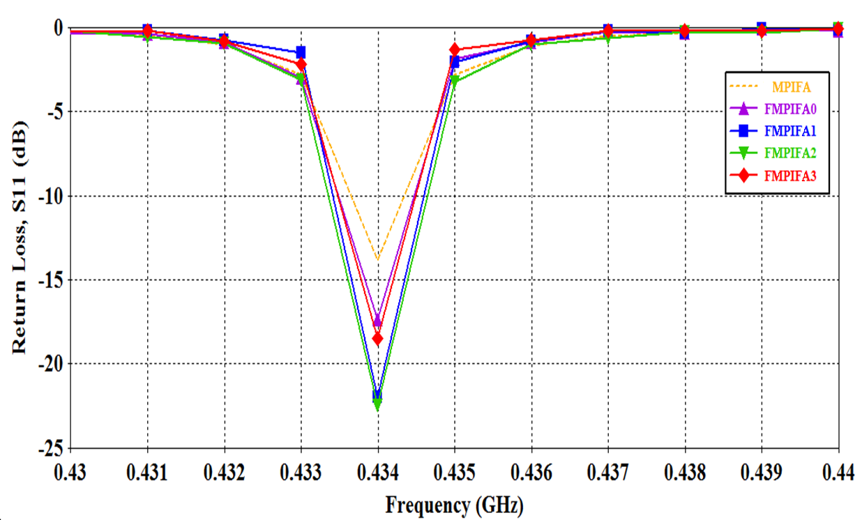 | Figure 11. The return loss curves for the optimized FMPIFA antennas. A result related to the MPIFA is given for comparison purposes |
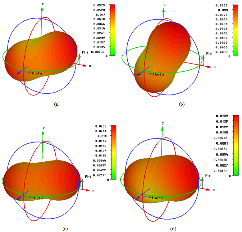 | Figure 12. Computed 3D linear radiation patterns of the optimized FMPIFA antennas. (a) Zero- order (b) First- order (c) Second- order (d) Third- order Minkowski island fractal |
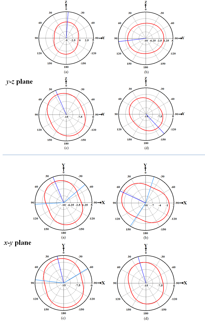
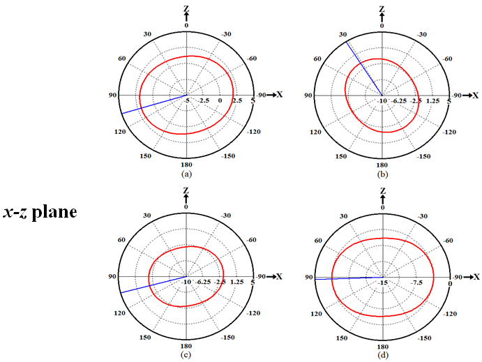 | Figure 13. Simulated 2D Radiation Patterns for the optimized FMPIFA antennas. (a) Zero order. (b) 1st order. (c) 2nd order (d) 3rd order fractal |
 | Figure 13. Simulated 2D Radiation Patterns for the optimized FMPIFA antennas. (a) Zero order. (b) 1st order. (c) 2nd order (d) 3rd order fractal |
Table 6. Simulation results of FMPIFA antennas at 434 MHz centre frequency
 |
| |
|
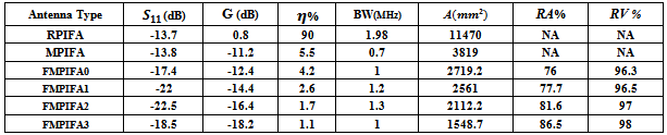
The obtained return loss for the optimized FMPIFA antennas is below the threshold value given in the fitness function (-17 dB). Therefore a good impedance matching has been obtained for the optimized antennas. It can be noticed from Figs. 12 and 13 that the radiation patterns are acceptable for WSN application for such small sized antennas because of the collaborative effort of SNs (i.e. When one SN has a weak signal in one direction a neighboring SN can route the data in that direction).Table 6 lists some antenna performance characteristics and the antenna size and volume miniaturization percentages for the optimized FMPIFA antennas (from the 0th- to the 3rd- order). For comparison purpose, performance characteristics of RPIFA antenna are shown in this table.
8. FMPIFA Implementation and Measurement Results
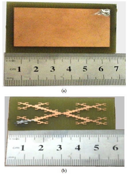 | Figure 14. The prototype optimized FMPIFA antennas. (a) The optimized FMPIFA0 antenna. (b) The optimized FMPIFA3 antenna design |
The photographs of the fabricated FMPIFA antenna prototypes are shown in Fig. 14. The performance of these prototypes was tested using VNA. Figs. 15 (a), and (b) show the comparison between the practical and the measured return loss values for the optimized FMPIFA0, and FMPIFA3, respectively.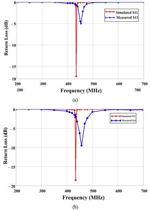 | Figure 15. The measured and simulated return loss values (a) optimized FMPIFA0 antenna. (b) optimized FMPIFA3 antenna |
The discrepancies of the frequency behaviours between the measured and simulated results are certainly due to small uncontrollable changes that may occur while placing the shorting pin and the feeding pin. The fabrication of the modified PIFA antenna is very sensitive to the dimension changes where any shift in the fabrication will shift the resonant frequency and hugely affect the input impedance. Nevertheless, the resonance measured has a slight frequency shift compared to the simulated one. The obtained resonant frequency is 434 MHz for the both FMPIFA0 and FMPIFA3 simulated antennas. Whereas it is 452.5 MHz for the FMPIFA0 and 457.5 MHZ for the FMPIFA3 measured antennas.
9. Conclusions and Discussion
Most antennas at low frequencies are large in size.Fractal geometry and optimization process can be used for designing a small scaled antenna.In this work Minkowski fractal PIFA configuration has been adopted to design miniaturized sized antennas for 434 MHz ISM frequency band, to be used in wireless sensor network; these antennas must have a very small size compared to the wavelength of the operating frequency.Four orders of Minkowski fractal PIFA antenna have been studied, optimized and modified for further miniaturization, since the main purpose of the study is to design a miniaturized size antenna of suitable performance for WSN applications. The results reveal that more than 68% reduction in overall antenna size can be obtained from the third Minkowski fractal order as compared with the conventional reference PIFA antenna. The performance characteristics are obtained with less than  return loss and 80% efficiency with nearly Omni-directional radiation pattern achieved. The 3rd-order fractal antenna has a just overall size of (72.3 × 49.67 × 9.6)
  (i.e., λ/9.6 × λ/14 × λ/72). The 0th- and the 3rd- fractal order of the optimized FPIFA antenna were fabricated then the return loss characteristics were measured using Vector Network. An acceptable match is obtained between the simulated and the measured results.A modified PIFA antenna was designed. The PSO-FIT design methodology has been applied to the first four Minkowski fractal modified PIFA antenna designs to minimize the area of RMPIFA antenna. An antenna size reduction obtained at the fourth stage (third fractal order) is over 86.5% compared to the area of RPIFA antenna. The volume reduction for FMPIFA3 antenna obtained exceeds 98% the volume of RPIFA antenna. The 3rd-order fractal antenna has a just overall size of (59.66 × 25.96 × 1.5)
  (i.e., λ/11.6 × λ/26.6 × λ/461). The zero and the third fractal orders of the optimized fractal modified PIFA antenna (FMPIFA0 & FMPIFA3) were fabricated and the return loss measurements were performed and compared with the simulated ones. The sensitivity of this design makes the fabrication process difficult and a small frequency shift exists between the simulated and the measured results with poor input impedance matching.
ACKNOWLEDGEMENTS
We want to express our gratitude to Electronic and Industrial Centre, Research and Development Department of Science and Technology Ministry for giving us all the help needed to fabricate the designed antennas and measure their response.
References
| [1] | D. Puccinelli and M. Haenggi, “Wireless Sensor Networks: Applications and Challenges of Ubiquitous Sensing”, IEEE Circuit and Systems Magazine, Vol. 5, Issue 3, pp. 19-31, 2005. |
| [2] | I. F. Akyildiz, and M. C. Vuran, Wireless Sensor Networks, United Kingdom, John Wiley & Sons Ltd, 2010. |
| [3] | Antenna Selection Guide by Richard Wallace available at: http://www.ti.com/lit/an/swra161b/swra161b.pdf |
| [4] | K. Phaebua, C. Phongcharoenpanich, D. Torrungrueng, and J. Chinrungrueng, “TwoRectangular Printed Spiral Antenna with U-Strip”, IEEE Antennas and Propagation Society International Symposium AP-S, pp. 1- 4, July 2008. |
| [5] | M. Manteghi and Y. Rahmat-Samii,"A novel Miniaturized Triband PIFA for MIMO Applications", Microwave and Optical Technology Letters, Vol. 49, No. 3, 2007. |
| [6] | I. Kim, J. Yook, and H. Park, "Fractal-Shape Small Size Microstrip Patch Antenna", Microwave And Optical Technology Letters, Vol. 34, No. 1, July 5 2002 |
| [7] | M. Al-uaim, "Design of New Miniaturized Fractal Microstrip Line Fed Printed Slot Antenna",EEE Internet Communications (BCFIC Riga) Baltic Congress on Future, pp. 148 – 152, 2011. |
| [8] | D. Naji, J. Aziz, R. Fyath, "Design and Simulation of Miniaturized Minkowski Fractal Aperture- Coupled Antenna for 5.8 GHz RFID Applications ",Journal of Emerging Trends in Computing and Information Sciences, VOL. 3, NO. 7, July 2012. |
| [9] | CST Microwave Studio: www.cst.com. |
| [10] | W. Liu, Z. Zhang, J. Zheng, and Z. Feng, “A Novel miniaturized antenna for ISM 433MHz wireless system”, IEEE Electrical Design of Advanced Packaging and Systems Symposium (EDAPS), Vol. 11, pp. 1-4, 2011. |
| [11] | W. Liu, Z. Zhang, and Z. Feng, “ISM 433-MHz Miniaturized Antenna Using the Shielding Box of Mobile Terminals”, IEEE Antennas and Wireless Propagation Letters, Vol. 11, pp. 330-333, 2012. |
| [12] | J. Robinson, and Y. Rahamat-Samii, "Particle Swarm Optimization in Electromagnetics", IEEE Transactions on Antennas and Propagation, Vol. 52, Issue 2, pp. 397-407,Feb. 2004. |
| [13] | LPKF ProtoMat S100 PCB prototyping machine catalog. Available at http://www.ece.ubc.ca/~leos/pdf/tools/lpkf/ProtoMatS100.pdf |
| [14] | Available athttp://www.anritsu.com/en-us/productssolutions/products/ms 4640a-series.aspx. |
 Abstract
 Reference
 Full-Text PDF
 Full-text HTML