-
Paper Information
- Next Paper
- Paper Submission
-
Journal Information
- About This Journal
- Editorial Board
- Current Issue
- Archive
- Author Guidelines
- Contact Us
International Journal of Electromagnetics and Applications
p-ISSN: 2168-5037 e-ISSN: 2168-5045
2013; 3(4): 65-69
doi:10.5923/j.ijea.20130304.02
Novel UWB Planar and Minimized Antennas Based on Composite Right/Left-Handed Transmission Lines for Electromagnetic Applications
 Abstract
 Reference
 Full-Text PDF
 Full-text HTML
Mohammad Alibakhshi Kenari
Electrical Engineering Department of Shahid Bahonar University of Kerman, Kerman, Iran
Correspondence to: Mohammad Alibakhshi Kenari, Electrical Engineering Department of Shahid Bahonar University of Kerman, Kerman, Iran.
| Email: |  |
Copyright © 2012 Scientific & Academic Publishing. All Rights Reserved.
In this paper, two novel ultra wideband (UWB) minimized antennas based on the composite right/left-handed transmission lines (CRLH-TLs) structures are designed. The proposed antennas are presented with best in size, bandwidth and radiation patterns. To realize characteristics of the antennas ψ-shaped gaps print into radiation patches are used. Overall sizes of the CRLH antennas are 24.8mm by 9.5mm by 1.6mm and 37.2mm by 9.25mm by 1.6mm, respectively. These antennas can cover the frequencies bandwidths from 2.8-11.8GHz and from 2.1-11.7GHz for VSWR < 2. The antennas highest gains and maximum radiation efficiencies are 7.71dBi and 54.93% at operation frequency 11GHz for first antenna and 7.02dBi at f=11.7GHz and 61% at f=10GHZ for second antenna, respectively.
Keywords: Ultra Wide Band (UWB) Antennas, Minimized Antennas, Printedψ-shaped Antennas, Composite Right/Left-handed Transmission Lines (CRLH-TLs), Metamaterial (MTM)
Cite this paper: Mohammad Alibakhshi Kenari, Novel UWB Planar and Minimized Antennas Based on Composite Right/Left-Handed Transmission Lines for Electromagnetic Applications, International Journal of Electromagnetics and Applications, Vol. 3 No. 4, 2013, pp. 65-69. doi: 10.5923/j.ijea.20130304.02.
Article Outline
1. Introduction
- Transmission lines are essential components in modern wireless systems, being used to connect antennas to transmitters and receivers, for impedance matching in mixers and amplifiers, or as resonant elements in oscillators and filters[1]. When the electrical wavelengths are shorter than or comparable to the physical dimensions of a network, the length becomes important and transmission line theory should be applied instead of standard circuit analysis. Thus high frequency transmission lines can be defined as transmission lines that are designed to carry electromagnetic waves whose wavelengths are shorter than or comparable to the length of the line. An electrical transmission line is a distributed parameter network, where voltages and currents can vary in magnitude and phase over the length of the line, and it can be analyzed by general transmission line model and equations[2]. The general transmission line approach provides insight into the physical phenomena of left handed materials and provides an efficient design tool for left-handed applications. The left-handed transmission line structures with lower loss and wider bandwidth have led to the development of novel microwave devices, such as new types super-lenses[3], microwave components[4-5] and leaky-wave antennas[6].Since left-handed MTMs based on composite right/left-handed transmission lines (CRLH-TLs) were introduced, various studies have been conducted of guided, refracted, and radiated wave components and systems[7-8].MTMs are artificially constructed materials that have electromagnetic properties not found in nature. The concept of MTMs with simultaneously negative permittivity and permeability, more commonly referred to as left-handed materials. In fact, a purely left-handed TL is not physical and can never be realized because of the parasitic effects. MTMs with left-handed properties have inevasible right-handed properties, known as composite right/left hand MTMs. During the past years, composite right/left-handed materials made by inserting periodic inclusions[9] with dimensions smaller than the guided wavelength,
 have attracted considerable attention in view of minimizing antenna size[10], which may lead to the development of new applications.In this paper, we proposed UWB minimized antennas based on CRLH MTM-TLs for communication units, radars and location tracing. In design of proposed antennas structures, we recommended and utilized of the novel methodologies for antennas size reduction based on MTMTLs and printed planar patches and for antennas bandwidth and radiation properties enhancement based on selection and optimization of the inductive and capacitive elements, as presented approaches detailed at next section.The paper is categorized as follows. We will be proposed and designed of two MTM antennas which have smaller size, broader bandwidth and superior radiation properties in comparison to conventional and UWB antennas, in Section 2. Section 3 consists of simulation results and antennas characteristics. Benefits of the proposed CRLH antennas presented in next section, and finally discussion and conclusion are raised.
2. Design Procedures of the Recommended Antennas Prototypes
- The proposed antennas are based on the CRLH MTM-TL unit cells. These planar antennas are designed on a Rogers_RT_Duroid5880 substrate with dielectric constant of 2.2 and 1.6mm thickness. These antennas are based on simplified planar mushroom structure unit cells. The unit cells are consists of host TLs with ψ-shaped gaps printed into radiation patches and rectangular and spiral inductors connected to ground plane through metallic via holes as set ups series capacitances CL and shunt inductances LL. Even if we intentionally provide only series capacitance and shunt inductance, parasitic series inductance LR and shunt capacitance CR effects, increasing with increasing frequency, will unavoidably occur due to currents flowing in the metallizations and voltage gradients developing between the metal patterns of the trace and the ground plane, which indicates that these inductance and capacitance cannot be ignored, hence a purely LH-TL cannot exist physically. Thus, the CRLH model represents the most general MTM structure possible. Antennas structures are excited by external port (i.e.; port 1) and their port 2 are matched to 50Ω load impedance. CRLH propagation along a given direction can be modeled by the 8-parameter unit cell lumped element circuit shown in Figs. 1 and 5. These models essentially exhibits a series capacitance CL and a shunt inductance LL[left-handed (LH)], corresponding to negative permeability and negative permittivity, respectively, but also includes a series inductance LR and a shunt capacitance CR[right-handed (RH)] associated with the magnetic and electric fluxes, respectively, intrinsic to any TL structures, and corresponding to positive permeability and permittivity, respectively. In addition to these four reactive parameters, one has the conventional lossy parameters RR and GR (RH), and the lossy parameters GL and RL (LH), which account for the dielectric loss associated with CL and the ohmic loss associated with LL, respectively, and which mostly represent radiation in antenna applications.In these designs, we presented a new theory based on employing printed planer methodology and CRLH MTM-TL for downsizing of the proposed antennas and also we utilized approaches based on designing of useful capacitive and inductive elements for extension of bandwidth and enhancement of radiation properties of the proposed antennas.
2.1. Deign Procedure of the UWB Minimized MTM Antenna Based on Four ψ-Shaped Unit Cells
- Presented antenna is formed of the four simplified planar mushroom structure ψ-shaped unit cells, each of which occupies only 6.2mm×9.5mm or 0.1λ0×0.158λ0 in terms of the free space wavelength at the operation frequency f=5GHz. The physical length, width and height of the antenna are 24.8mm, 9.5mm and 1.6mm, or, 0.41λ0, 0.158λ0 and 0.02λ0, respectively. The equivalent circuit model of the antenna for one unit cell and whole layout structure based on the CRLH-TL are shown in Figs. 1 and 2, respectively.
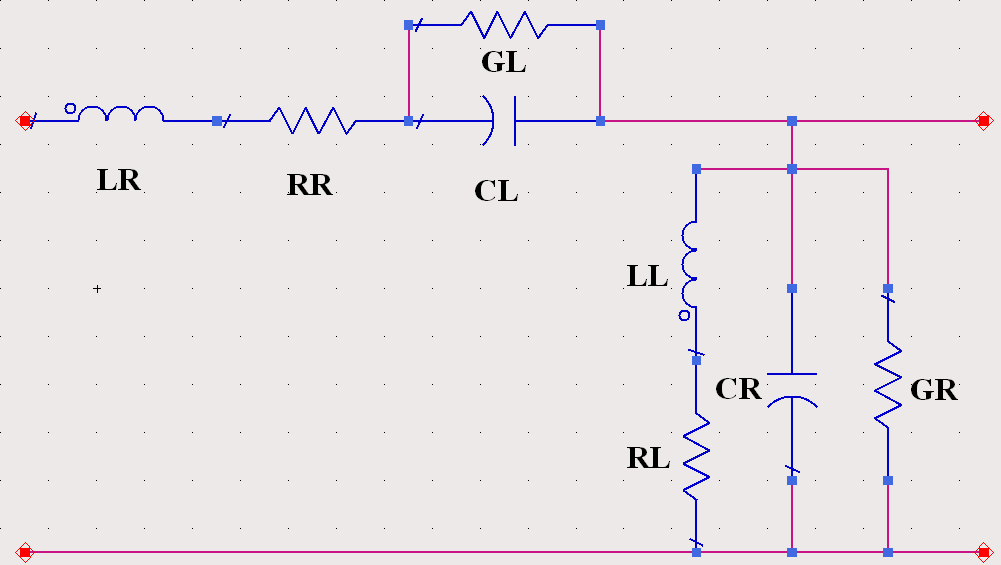 | Figure 1. Circuit model for one unit cell of a CRLH TL metamaterial structure with RH parameters (LR; RR; CR; GR) and LH parameters (CL; GL; LL; RL). A d-dimensional (d = 1; 2; 3) metamaterial structure of size ld= (Np)d is formed by periodically repeating a cell of this type N times in d directions |
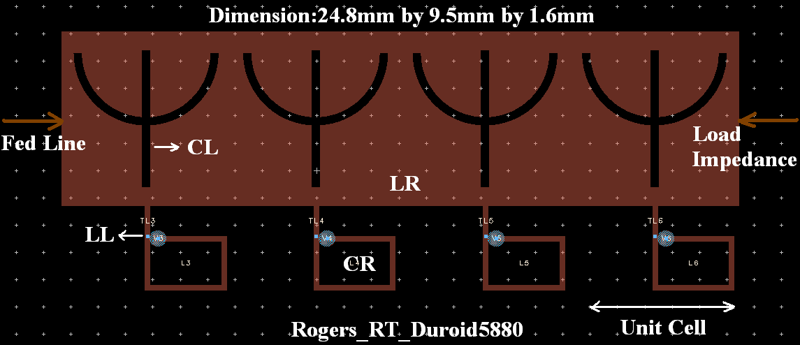 | Figure 2. Geometry of the antenna structure composed of four unit cells |
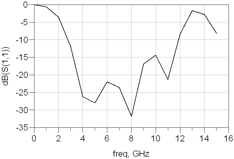 | Figure 3. Simulated reflection coefficient (S11 parameter) |
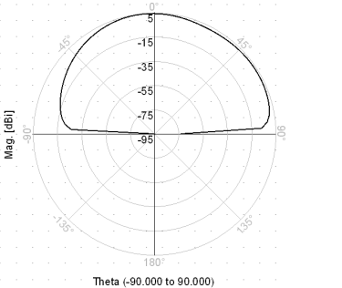 | Figure 4. Simulated gain pattern in elevation plane (Φ=0О) at fr =8 GHz |
2.2. Extended Bandwidth Design for CRLH-TL Based Small Antenna
- In this section, we presents the printed ψ-shaped antenna structure that constructed of three unit cells with extended bandwidth in comparison to proposed antenna in previous section. The design procedures of both proposed antennas are completely similar together, but number of unit cells contribution in antennas structures, circuit models and layout structures of both antennas are different with together. These proposed differences caused which later proposed antenna providing enhancement bandwidth than first designed antenna. Equivalent circuit model for one unit cell and configuration of last antenna are shown in Figs. 5 and 6, respectively.Obviously in design of later antenna for extension of bandwidth, arrangement and number of unit cells accompanying inductive elements are changed than first antenna prototype, which lead to becoming greater the dimension of this antenna than first antenna. This antenna covers frequency bandwidth from 2.1- 11.7GHz and consists of 9.6GHz bandwidth, which corresponds to 139.13% operational bandwidth. Overall size of the antenna is 37.2×9.25×1.6mm3 or, 0.62λ0× 0.154λ0× 0.02λ0 in terms of the free space wavelength at the operation frequency f=5GHz. The antenna gain and radiation efficiency at fr=5GHz are 5.55dBi and 35.22%, respectively. The simulated reflection coefficient (S11 < -10dB) and radiation gain pattern at 5GHz are plotted in Figs. 7 and 8.
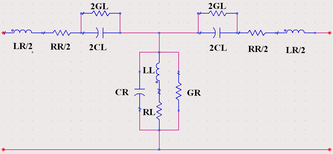 | Figure 5. Circuit model for one unit cell of a CRLH TL metamaterial structure with RH parameters (LR; RR; CR; GR) and LH parameters (CL; GL; LL; RL). A d-dimensional (d = 1; 2; 3) metamaterial structure of size ld= (Np)d is formed by periodically repeating a cell of this type N times in d directions |
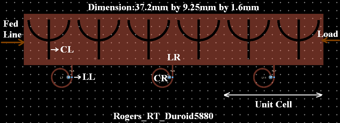 | Figure 6. Configuration of the antenna structure composed of three unit cells |
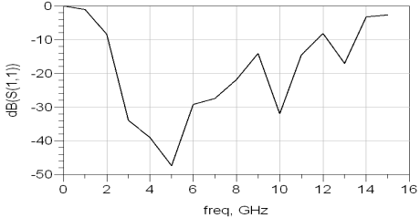 | Figure 7. Simulated S11 parameter |
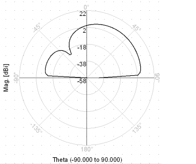 | Figure 8. Simulated radiation gain pattern in Φ=0О and at fr =5GHz |
3. Simulation Results and Discussions of the Proposed Printed UWB Minimized Antennas
- The antennas were designed on Rogers_RT_Duroid5880 substrates with
 and thickness h=1.6mm. Each unit cell of the first and second proposed antennas occupies only 6.2mm×9.5mm and 12.4mm×9.25mm, respectively and overall sizes of the antennas are 24.8mm×9.5mm×1.6mm and 37.2mm×9.25mm×1.6mm, respectively. Figs. 3 and 7 are shows the simulated return losses of these antennas. The simulated results were obtained using Agilent ADS full-wave simulator. As illustrated in Fig.3 the simulated return losses bandwidth (S11<-10dB) of the first antenna is 9GHz (2.8-11.8GHz), which corresponds to 123.28% practical bandwidth. The simulated return losses bandwidth (S11<-10dB) of the second antenna that shown in Fig.7 is 9.6GHz (2.1-11.7 GHz), which corresponds to 139.13% practical bandwidth. For first antenna, radiation gains and efficiencies at 2.8, 5 and 11.8 GHz are 2.16dBi and 45.89%, 5.37dBi and 46.21% and 5.7dBi and 44.24%, respectively. For second antenna same parameters at 2.1, 10 and 11.7 GHz are 0.4dBi and 16.4%, 6.7dBi and 61%, and 7.02dBi and 49.45%, respectively. Also according to Figs. 4 and 8 radiation patterns of the suggested antennas have unidirectional characteristics.
 4. Benefits of the Recommended CRLH-Based Antennas
- Proposed CRLH-based antennas are ultra wideband (UWB), low profile and ultra miniature on a printed circuit board, and consist of superior radiation performances. In fact, the proposed CRLH-based antennas are very smaller than conventional antennas and have broader bandwidth than UWB antennas while offering better performances. Furthermore, unlike conventional three dimensional (3-D) antennas - which must be designed, tooled and fabricated as a complex metal-and-plastic assembly- the proposed antennas shown in Figs. 2 and 6 are simple three dimensional (3-D) structures which easily designed, tooled and fabricated. Copper artwork is printed directly on a printed circuit board using standard printed-circuit board manufacturing techniques. This offers manufacturers faster time to market and reduced bills-of-materials due to the simplified design. It also offers a greatly reduced need for fabrication and assembly of antenna components. In addition, the CRLH-based antenna's ability to concentrate electromagnetic fields and currents near their antenna structures results in achieving better performance. Therefore, proposed UWB CRLH MTM minimized antennas can be practical and feasible for commercial uses. CRLH-based antennas cover frequency bands 2.8-11.8GHz and 2.1-11.7GHz for radar, location tracing, and data transmissions, that were approved by FCC in 2002 [11].
5. Conclusions
- In this paper, we introduced a new concept of the antenna size reduction based on MTM design technology and printed planar methodology and also a novel idea of the antenna bandwidth enhancement accompanying superior radiation properties based on employing appropriate capacitive and inductive elements attending their optimized values. All results demonstrated that the proposed CRLH-based antennas have wider bandwidth, smaller size and superior radiation properties in comparison to other conventional and UWB antennas. These antennas have the advantages of small size, UWB, lightweight, high gain and efficiency, unidirectional radiation patterns, simple implementation and low cost. The simulated results exhibit that the proposed antennas should be potential candidates to use in the modern wireless communication systems, radars and location tracing.
ACKNOWLEDGEMENTS
- The author would like to express his sincere thanks to Research Institute for ICT of Iran (Contract number 6987/500/T).