Sakshi Bhardwaj, R. L. Yadava, Sonam Thakur
Galgotias college of Engineering & Technology, Greater Noida, U.P., India
Correspondence to: Sonam Thakur, Galgotias college of Engineering & Technology, Greater Noida, U.P., India.
| Email: |  |
Copyright © 2012 Scientific & Academic Publishing. All Rights Reserved.
Abstract
In this paper, characteristics of electromagnetically coupled (EM) dielectric loaded rectangular patch have been analyzed using HFSS. The proposed antenna structure has been studied with single and double dielectric loadings, basically to provide necessary protection to patch antenna from environmental hazards. The projection area of two layered patch antenna is kept same as single layered patch antenna. The effect on performance characteristics such as resonant frequency, gain, directivity, efficiency of rectangular patch antenna with varying permittivity of dielectric material has been studied. The proposed structure is fed with coaxial probe feed which leads to good impedance matching and its operating frequency is 6 GHz.
Keywords:
EM Coupled Patch Antenna, Dielectric Loading, Resonant Frequency, Directivity
Cite this paper: Sakshi Bhardwaj, R. L. Yadava, Sonam Thakur, The Characteristics of Electromagnetically Coupled Two Layered Dielectric Loaded Patch Antenna, International Journal of Electromagnetics and Applications, Vol. 3 No. 4, 2013, pp. 43-64. doi: 10.5923/j.ijea.20130304.01.
1. Introduction
Microstrip antenna is gaining more importance these days because it possesses attractive features and unique properties such as: low profile, light weight, low cost and flexibility. Due to the above features microstrip patch antenna is widely being used for communications applications. However, narrow bandwidth and low gain are the major disadvantages of the patch antenna. The issues of increasing gain and bandwidth of microstrip antenna elements has been considered by several researchers.In general a dielectric layer is almost equivalent to any physical condition changes in microstrip patch antenna due to snow, ice or by introduction of a radome in the manufacturing stage for the purpose of protection from the environmental hazards. The performance characteristics of the antenna structure may be adversely affected if relative permittivity and thickness of the dielectric substrate using for design, are not chosen properly. It has been observed that the resonant frequency of the microstrip antennas is shifted which cause unexpected changes in the behavior of the antenna When the patch antenna is covered with dielectric sheet (called superstrate), its properties like effective dielectric constant, losses, Q factor change. The change in effective dielectric constant is of much more importance than any other characteristics. The amount of change depends on the thickness and relative permittivity of dielectric loading. For this reason, it is important to analyze dielectric loading effects so that the performance of the antenna may be understood better or a proper choice of cover parameters may be used. Available lectures revel that significant affords have been made by antenna engineers to study the characteristics of EM coupled patch antennas. In 1983, A. Sabban designed and tested a two-layer stacked antenna working over S to Ku band[1]. Later H. Y.Yang and N.G.Alexopolos, proved that it is possible to enhance gain of printed circuit antennas by applying multiple superstrates[2]. Further, a two layered electromagnetically coupled antenna (EMCP) operating in the broadband region was studied for describing the effects of varying the thickness of the superstrate and resonant frequency, impedance bandwidth, 3dB beam width were calculated[3].In 1990, a rectangular patch antenna with two coupled layers was investigated, and the effects of varying distance between the two layers were examined for the bandwidth and gain. Along with this, the changing the relative sizes of the parasitic and fed patches was also considered in the study[4]. Latter J.S.Row and K.L.Wong studied a rectangular microstrip antenna and presented the complex resonant frequency analysis with superstrate loading. The obtained results show a significant variation when the superstrate permittivity is greater than that of substrate[5]. A circularly polarized rectangular patch antenna was analyzed using spectral domain analysis, and the effects of dielectric superstrate were studied by Lei Zhu, Eikichi Yamashita and Ikuhiro Jouishi[6]. An enhanced gain circular region was obtained by cutting slits in square patch with circular radiation and covering the antenna by a high permittivity superstrate[7]. In 2001, A.K.Verma and Nasimmuddi observed an improvised version of the wolff model (cavity model) with isotropic/anisotropic substrate and superstrate to calculate the resonant frequency and input impedance of the patch antenna[8]. Next year, a multilayer miniature patch antenna was proposed. The comparative results of the single and two layered patch antenna showed an increase in the bandwidth by 5% of the multi layer antenna. In another design, the upper patch was cut in to the bow-tie shape, which produced a good radiation pattern[9]. In 2003, a simple formulation for accurate computation of the resonant frequency applicable for both high and low dielectric constant superstrates was presented. The results were in close agreement with the present theories and can be applied to conventional antennas also[10].A neural network model was developed for the variation in the resonant frequency of a rectangular microstrip antenna with dielectric loading. The proposed model was found to be in good agreement when simulated using method of moments[11].Self biased films are successfully introduced into patch antenna .as a result novel patch antenna design with spin spray deposited ferrite film have led to miniaturised patch antennas on magneto dielectric substrate/superstrate with enhanced bandwidth ,improved directivity and efficiency [12].Recently, a method for accurate calculation of the resonant frequency considering the effect of superstrate layer has been presented using variation in the patch dimensions. The antenna performances were also investigated for various cases of permittivity and thickness of the superstrate layer[13].In this paper, a patch antenna is designed to operate at 6 GHz frequency. This design is based on the various selection criteria such as thickness of dielectric material and dielectric constant (permittivity) for loading. Effect on the parameters with respect to change in dielectric constant of dielectric loading layer has been simulated and analyzed. The primary effect of such loading is the change in the resonant frequency of the antenna which has been presented in this paper.
2. Antenna Design
The proposed antenna consist of a printed rectangular patch antenna with dimension 1.7cm x 1.3cm on Roger RO4232 substrate of thickness h=0.0762cm and dielectric constant (εr=3.2). The structure incorporates an antenna element, dielectric material and a vertical coax probe connected to the patch. The substrate has following dimensions: L= 4cm and W= 5.2cm. The transmission line model will be used to design the antenna.Step 1: Calculation of the patch Width (W): The width of the Microstrip patch antenna is given by: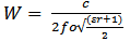 | (1) |
Where W is the width of the patch in (cm),c is the speed of the light ,fo is resonant frequencyεr is the dielectric constant of the substrate .Substituting c = 3e8 m/s, ε r = 3.2 and f o = 6 GHz, we get:W = 1.7cmStep 2: Calculation of Effective dielectric constant (εreff): The effective dielectric constant is calculated as: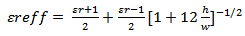 | (2) |
Where h is the height of substrate.Substituting εr = 3.2, W = 1.7 cm and h = 0.0762 cm we get: εreff = 2.8Step 3: Calculation of the Effective length (Leff): The effective length is given as: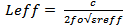 | (3) |
Substituting ε reff = 2.8, c = 3e8 m/s and f o = 6 GHz we get:L eff = 1.4 cmStep 4: Calculation of the length extension (ΔL): The length extension is given as: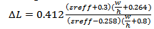 | (4) |
Putting the values, we get ΔL = 0.033 cmStep 5: Calculation of actual length of patch (L ): The actual length is obtained by :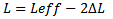 | (5) |
Substituting the values, we get:L= 1.3 cmA. Single Patch Antenna with Single LoadingThe geometry of rectangular patch antenna covered with single layer of dielectric material is depicted in Figure 1. The loading parameters chosen are as follows:Case 1: Dielectric material FR4 with dielectric constant 4.4 (εr1= 4.4).Case 2: Dielectric material for dielectric loading is RT/ Duroid-5880 with dielectric constant 2.2 ( εr1 = 2.2).Case 3: Magneto dielectric is used for loading. Magnetic thin films provide a unique opportunity for achieving self-biased magnetic antenna substrates with µr>1 at frequencies greater than 1 GHz (εr1=1.6, µr1=1.6).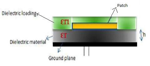 | Figure 1. Geometry of single patch antenna with single loading |
B. Single Patch Antenna with Double LoadingThe proposed geometry for the above antenna is shown in Figure 2. In this, the patch is covered with two layers of different dielectric materials. Three cases of study are:Case 1: Dielectric material RT/Duroid-5880 with dielectric constant 2.2 is used for first loading and FR4 dielectric material with dielectric constant 4.4 for second loading (εr1 < εr2) .Case 2: Dielectric material RT/Duroid-5880 is used for both loading (εr1= εr2).Case 3: Dielectric material FR4 is used for first loading and RT/Duroid -5880 for second loading (εr1 > εr2).Case4: Magneto dielectric is used for both loading. (εr1=1.6, µr1=1.6).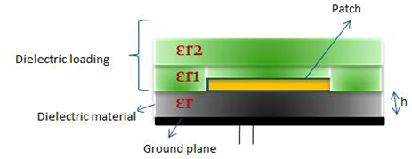 | Figure 2. Geometry of single patch antenna with double loading |
C. Stacked Patch Antenna with Single LoadingProposed geometry of stacked patch antenna is shown in Figure 3. in which two stacked patches are designed with single loading. Three cases studied are:Case 1: εr1= 4.4,Case 2: εr1 = 2.2.Case 3: εr1=1.6, µr1=1.6.D. Stacked Patch Antenna with Double LoadingThe proposed geometry of stacked patch antenna is shown in figure 4 where two stacked patches are covered with two layers of different dielectric materials which have different dielectric constants. Three cases studied are:Case 1: εr1 < εr2,Case 2: εr1= εr2,Case 3: εr1 > εr2,Case 4: εr1=1.6, µr1=1.6, εr2=1.6, µr2=1.6,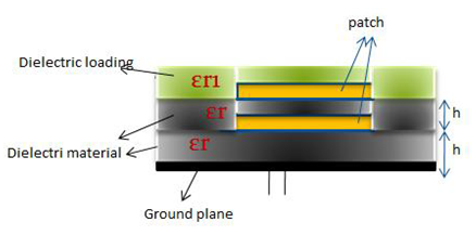 | Figure 3. Geometry of stacked patch antenna with single loading |
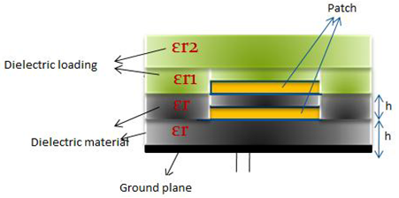 | Figure 4. Geometry of stacked patch antenna with double loading |
3. Results
a. Result of Single Patch Antenna with Single LoadingCase 1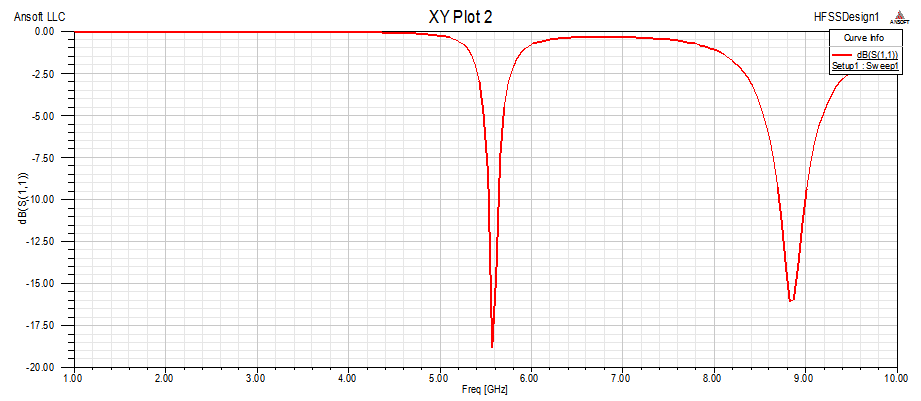 | Figure 5(a). Return Loss vs Frequency |
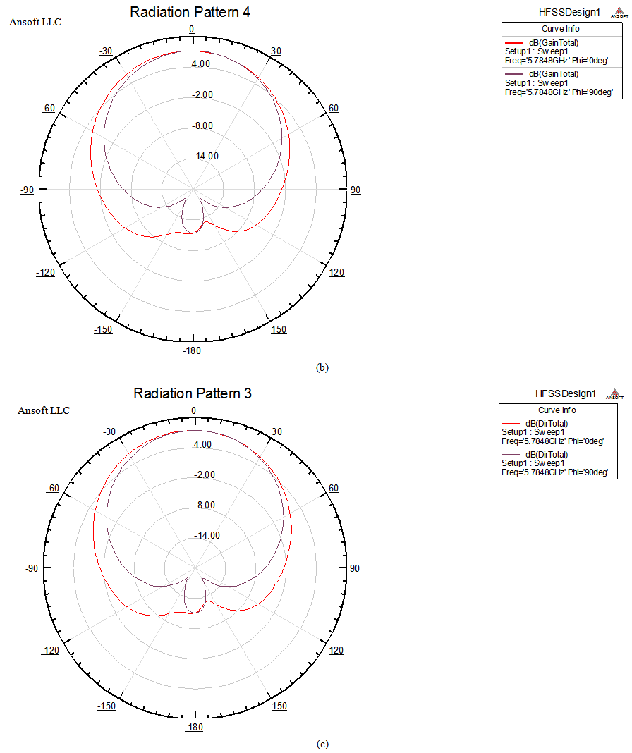
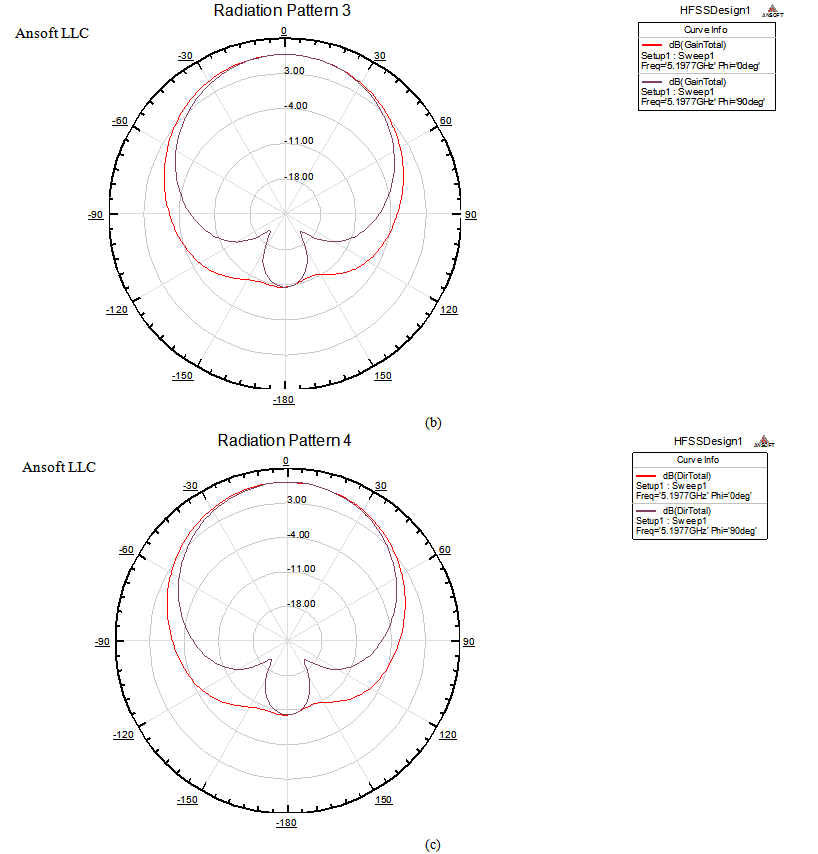
 | Figure 5(b),(c). Radiation Pattern for Gain and Directivity |
Case 2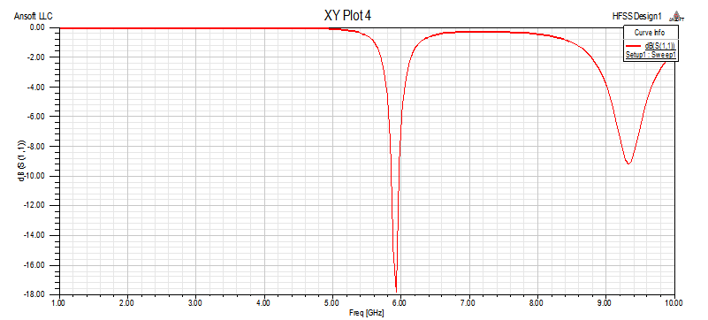 | Figure 5(d). Return Loss vs Frequency |
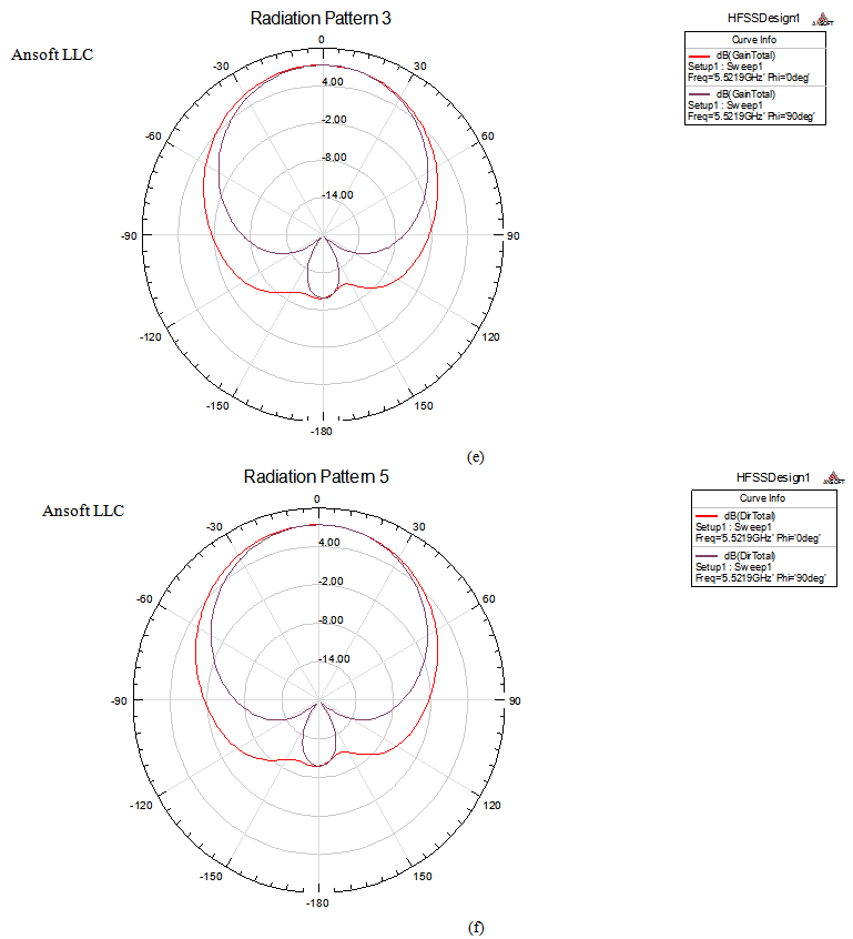
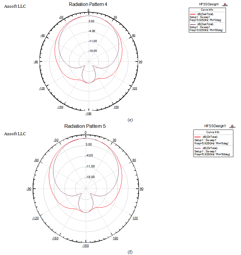 | Figure 5(e),(f). Radiation Pattern for Gain and Directivity |
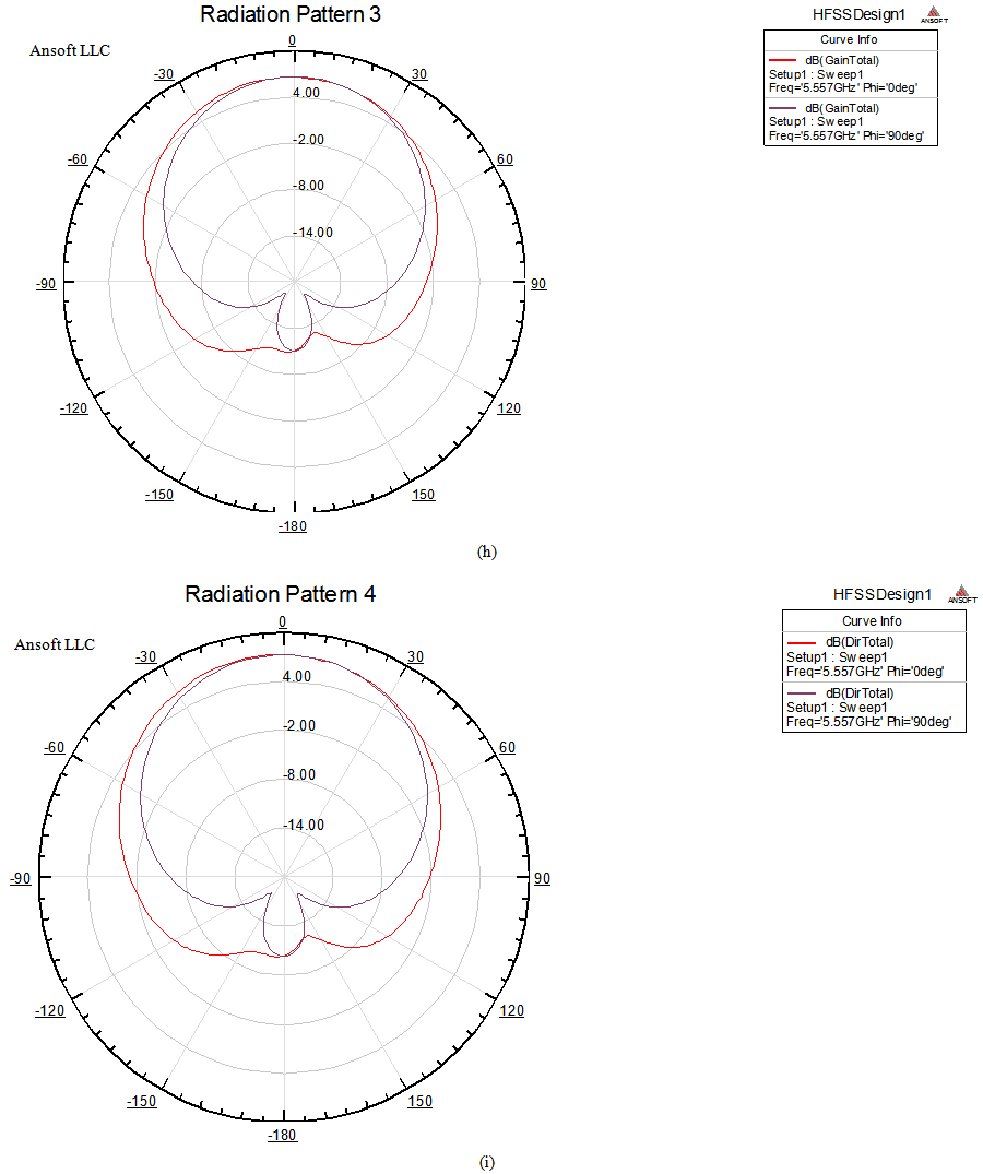
Case 3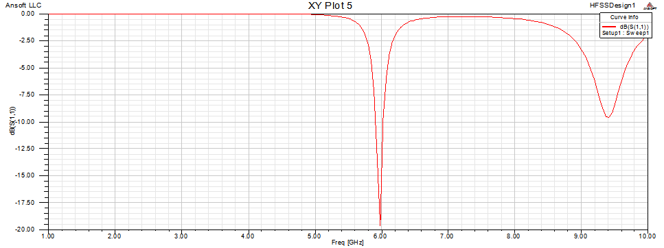 | Figure 5(g). Return Loss vs Frequency |
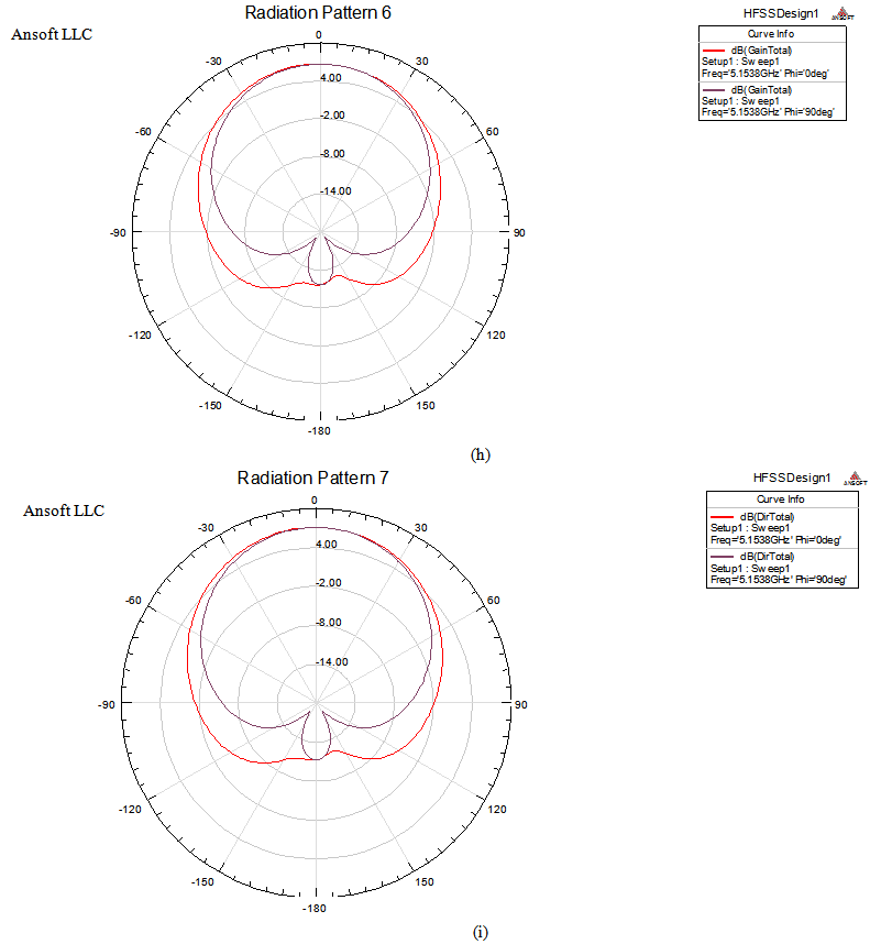
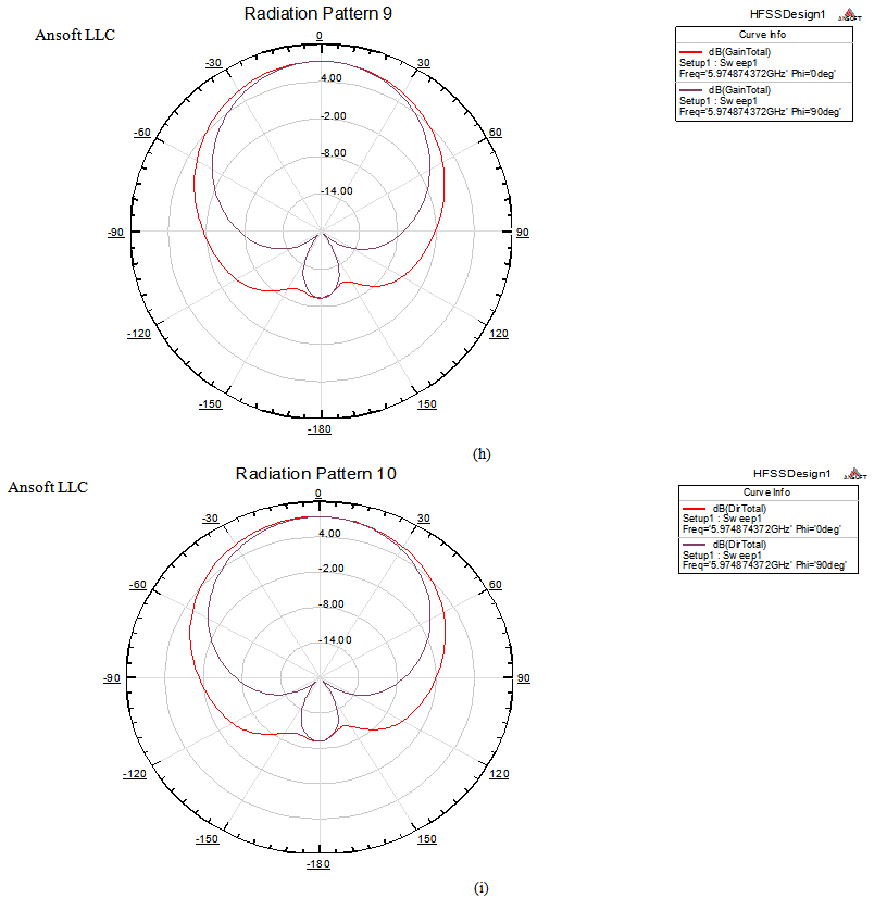 | Figure 5(h),(i). Radiation Pattern for Gain and Directivity |
b. Result of Single Patch Antenna with Double LoadingCase 1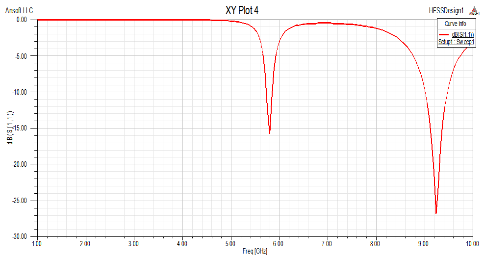 | Figure 6(a). Return Loss vs Frequency |
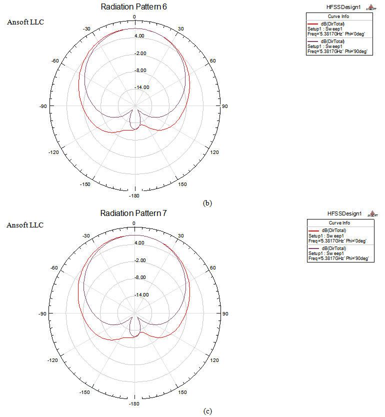
 | Figure 6(b),(c). Radiation Pattern for Gain and Diretivity |
Case 2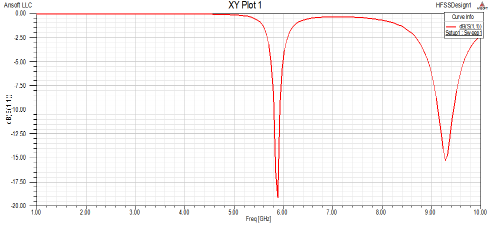 | Figure 6(d). Return loss vs Frequency |
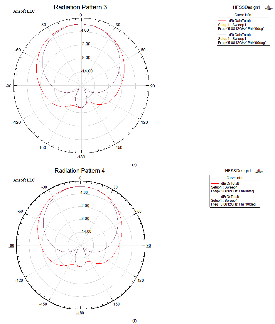 | Figure 6(e),(f). Radiation Pattern for Gain and Directivity |
Case 3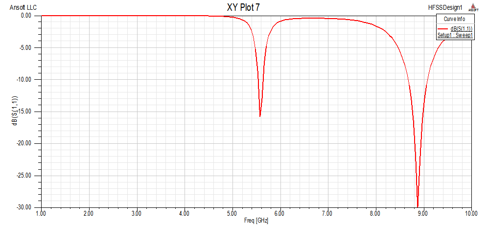 | Figure 6(g). Return Loss vs Frequency |
 | Figure 6(h),(i). Radiation Pattern for Gain and Directivity |
Case 4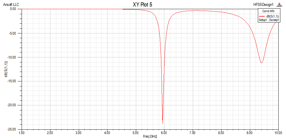 | Figure 6(j). Return Loss vs Frequency |
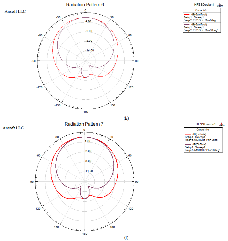
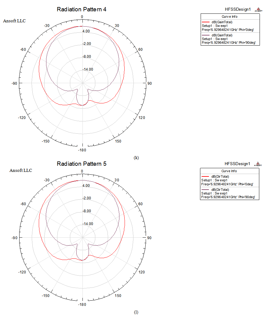 | Figure 6(k),(l). Radiation Pattern for Gain and Directivity |
c. Result of Stacked Patch Antenna with Single LoadingCase 1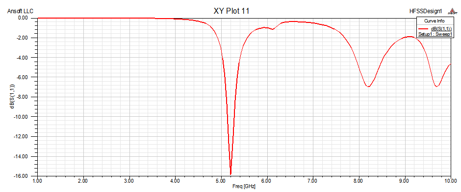 | Figure 7(a). Return Loss vs Frequency |
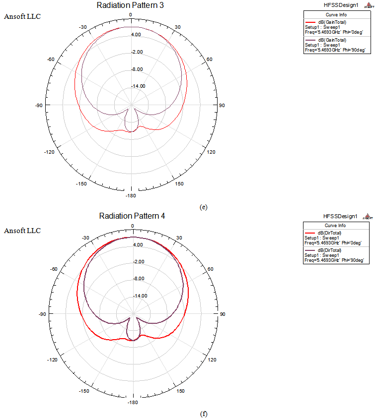
 | Figure 7(b),(c). Radiation Pattern for Gain and Directivity |
Case 2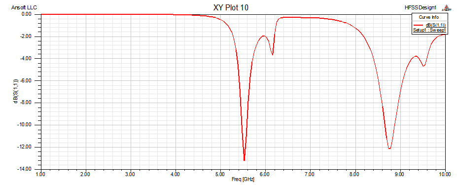 | Figure 7(d). Return Loss vs Frequency |
 | Figure 7(e),(f). Radiation Pattern for Gain and Directivity |
Case 3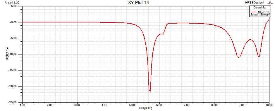 | Figure 7(g). Return Loss vs Frequency |
 | Figure 7(h),(i). Radiation Pattern for Gain and Directivity |
Result of Stacked Patch Antenna with Double LoadingCase 1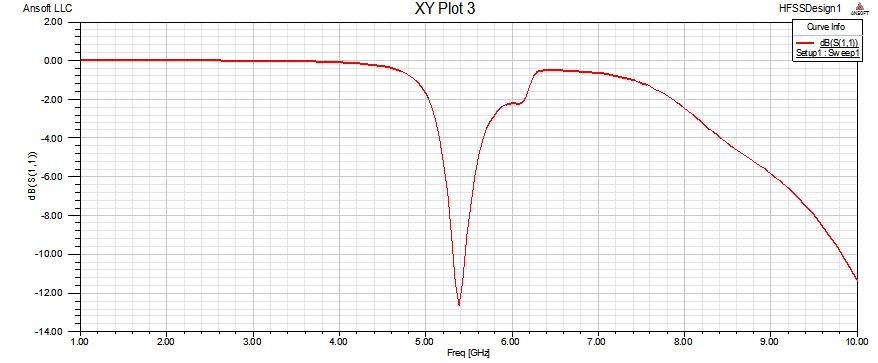 | Figure 8(a). Return Loss vs Frequency |
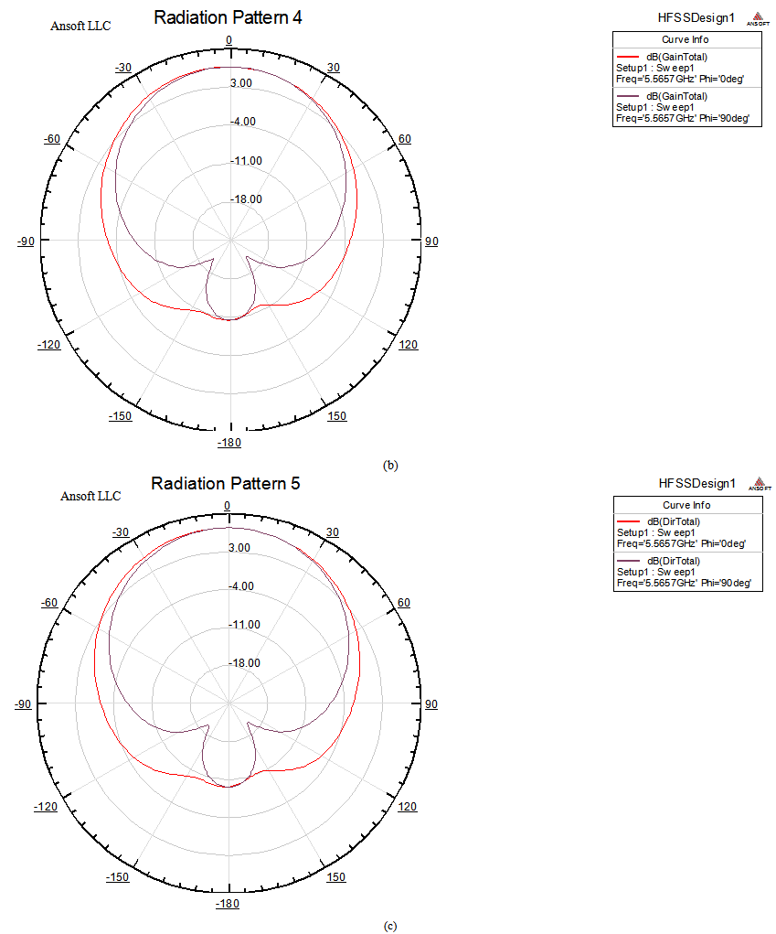
 | Figure 8(b),(c). Radiation Pattern for Gain and Directivity |
Case 2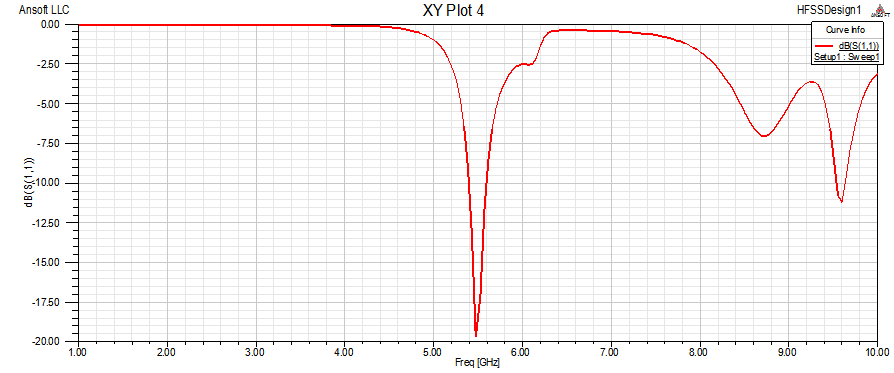 | Figure 8(d). Return Loss vs frequency |
 | Figure 8(e),(f). Radiation Pattern for Gain and Directivity |
Case 3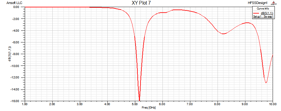 | Figure 8(g). Return Loss vs Frequency |
 | Figure 8(h),(i). Radiation Pattern for Gain and Directivity |
Case 4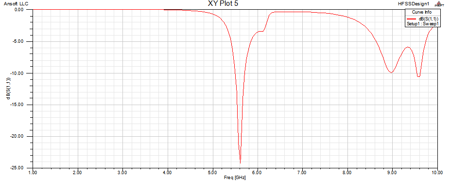 | Figure 8(j). Return Loss vs frequency |
 | Figure 8(k),(l). Radiation Pattern for Gain and Directivity |
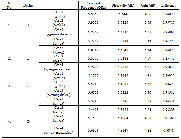
The following Table presents all the obtained results in terms of resonant frequency, Directivity, Gain and Efficiency.VI. Fabrication and testing resultsd. Fabrication of Single Patch Antenna with RT/Duroid 5880 Single LoadingAfter the modeling of probe feed patch antenna and achieving results we came to fabrication part. RT/Duroid 5880 substrate are used for dielectric loading. The dielectric constant of the dielectric loading is 2.2 and the thickness is 0.16cm. The substrate size for every fabricated antenna is 4 x 5.2 cm.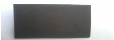 | Figure 9(a). Front View of Fabricated Patch Antenna |
Table I. Combined Results
 |
| |
|
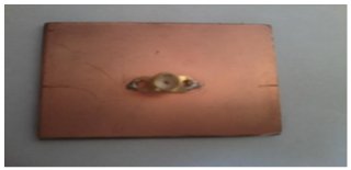 | Figure 9(b). Back View of Fabricated Patch Antenna |
e. Testing ResultTesting of patch antenna is done by network analyzer. Network analyzers are used mostly for high frequencies. Network analyzer is an instrument used to analyze the properties of electrical network, especially those properties associated with the reflection and transmission of electrical signals known as scattering parameters.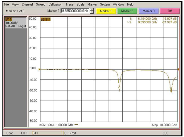 | Figure 10. Tested Result of Fabricated Patch Antenna |
The testing results of single patch antenna with single loading. The dielectric material RT/Duroid 5880 is used for loading. The antenna is designed at 6 GHz frequency. Even though antenna is desired to operate at this frequency, when tested practically it is found that its resonant frequency is 6.1 GHz.
4. Conclusions
Behavior of the patch antenna due to the effect of dielectric loading having different dielectric constants is investigated. Dielectric constant play major role in overall performance of patch antenna. The study reveals that dielectric loading not only changes the resonant frequency but also affects its other parameters such as gain, directivity and efficiency. It has been observed that resonant frequency of patch antenna is shifted to a lower value after compared all cases as a result of dielectric loading with dielectric constant 2.2 is used on antenna . Dielectric loading with magneto dielectric provides less frequency shift which is closer to the operating frequency i.e. 6 GHz and other parameters are improved after comparison when dielectric loading with lowest dielectric constant (2.2) is used.
References
| [1] | A.Sabban, “A new broadband stacked two-layer microstrip antenna”, IEEE Trans. Antenna Propagat. Soc. Int. Symp. Dig., pp. 63–66, 1983. |
| [2] | H.Y.Yang and H.G. Alexopoulous, “Gain enhancement methods for printed circuit antennas through multiple superstrates”, IEEE Trans. Antennas Propagat., vol. AP-35, pp.860–863, 1987. |
| [3] | R.Q. Lee and A.J Zaman, “Effects of dielectric superstrates on a two layer electromagnetically coupled patch antenna”, IEEE Trans. Antennas Propagt., 1989. |
| [4] | R.Q.Lee and K.F.Lee, “Experimental study of the two–layer electromagnetically coupled rectangular patch antenna”, IEEE Trans. Antennas and Propagat., vol 38, no 8, 1990. |
| [5] | Jeen-Sheen Row and Kin-Lu Wong, “Resonance in a superstrate-loaded rectangular microstrip structure”, IEEE Trans. On Microwave Theory And Tech., vol 41, No.8, 1993. |
| [6] | Lei Zhu, Eikichi Yamashita and Ikuhiro Jouishi, “ Spectral domain analysis of circularly polarized rectangular patch antennas with a dielectric superstrate”, IEEE Trans., 1996. |
| [7] | Chih-Yu Huang and Jian-Yi Wu, “Compact microstrip antenna loaded with very high permittivity superstrate”, IEEE Trans., 1998. |
| [8] | A.K Verma and Nasimuddin, “Input impedance of rectangular microstrip patch antenna with iso/anisotropic substrate-superstrate”, IEEE Microwave and Wireless Components Letters, vol 11, No.11, 2001. |
| [9] | R. Chair and K.M. Luk “Measurement and analysis of miniature multilayer patch antenna” , IEEE Trans. Antenna Propag. , vol.50, pp.244-250, 2002. |
| [10] | Debatosh Guha and Jawad.Y.Siddiqui, “Resonant frequency of circular microstrip antenna covered with dielectric superstrate”, IEEE Trans. On Antennas and Propagat., vol 51, No 7, 2003. |
| [11] | Samik Chakraborty, Sabyasachi Mandal and Bhaskar Gupta, “Neural network modeling for the fast estimation of superstrate loading effect on rectangular microstrip patch antennas”, IEEE Trans., 2007. |
| [12] | G.M.Yang and K.Naishadham, “Loading effects of self biased magnetic films on patch antennas with substrate/superstrate sandwich structure”, IET Microw. Antennas Propag., vol 4, pp.1172-1181, 2010. |
| [13] | R. K. Yadav and R. L. Yadava,"Performance analysis of superstrate loaded patch antenna and abstain from environmental effects," International Journal of Engineering Science and Technology (IJEST), Vol. 3, No. 8, pp. 6582-6591, August 2011. |
| [14] | R. K. Yadav and R. L. Yadava,"Effect on performance characteristics of rectangular patch antenna with varying height of dielectric cover," International Journal of Power Control Signal and Control (IJPCSC),Volume 2, No. 1, pp. 55-59, March 2011. |
| [15] | Samir Dev Gupta and Amit Singh, “Design and analysis of multidielectric layer microstrip antenna with varying superstrate layer characterstics”, International Journal of Advances in Engineering & Tech., vol 3, pp.55-68, 2012. |
 Abstract
 Reference
 Full-Text PDF
 Full-text HTML