Budumuru Srinu , C Dharma Raj , P V Y Jayasree
Department of ECE, GITAM Institute of Technology, GITAM University, Visakhapatnam, India
Correspondence to: Budumuru Srinu , Department of ECE, GITAM Institute of Technology, GITAM University, Visakhapatnam, India.
| Email: |  |
Copyright © 2012 Scientific & Academic Publishing. All Rights Reserved.
Abstract
The reflection loss of an electromagnetic wave from a material is important parameter in the design of electromagnetic shielding techniques. May the designed circuit can show inefficiency because of the radiation interference from the external sources. To construct proper electronic circuit precautions has to be taken in terms of electromagnetic interferences. The techniques to overcome the electromagnetic interference are electromagnetic compatibility. In this paper mainly discussed about one of the compatibility techniques, shielding by the conductive materials. The shielding ability of the conductive material can be analyzed in terms of reflectivity for a single shielding conductive material. Conductors are best reflectors for electromagnetic waves, when ever electromagnetic waves can be incident on it. The reflectivity of these conductive materials can depends on the temperature. Based on the properties of the conductor as the temperature changes the conductivity of the conductor can changes, by it the reflectivity of the material can also changes. The analysis can be made for reflectivity of a conductive material with respective to the temperature at particular frequency. The thickness of the conductive material not considered here. The variation of reflectivity for different conductive materials at 100 MHz frequency can be analyzed. As the temperature increases the reflectivity of the material can be decreases in small percent. The best reflectivity can be achieved at low temperature. The analysis also carried by comparing at different frequencies for the shielding material.
Keywords:
Resistivity, Reflectivity, Shielding
Cite this paper: Budumuru Srinu , C Dharma Raj , P V Y Jayasree , Surveillance of Reflectivity for a Conductor Shield Based on Temperature and Frequency, International Journal of Electromagnetics and Applications, Vol. 3 No. 1, 2013, pp. 1-8. doi: 10.5923/j.ijea.20130301.01.
1. Introduction
Electromagnetic shielding[1][7] is of prime concern in the design of any circuit in order to avoid electromagnetic interference from external sources. A good conductingenclosure of the circuit would stop electromagnetic interference from external sources. The reflectivity of the different conductive materials can be analyzed by considering the incident of electromagnetic wave at the interface of free space and conductor for various temperatures. As the frequency changes the reflectivity conductive material will changes but here the complete concentration is about change in reflectivity based on temperature for a fixed frequency. Which is 210mm wide and 285mm long. The margins must be set as follows:For change in temperature the conductivity of the conductor changes as the conductivity of the conductor changes, the reflectivity also changes. So to explain this analysis for different conductor materials can be selected like copper, aluminum, titanium, iron. Initially the variation of conductivity of these materials can be analyzed and then the variation of reflectivity can be observed. As the temperature increases the reflectivity will decreases because the reflection loss increases. The variation of the reflectivity for a shielding material at different frequencies also observed.
2. Experiment
2.1. Resistivity of the Conductor with Temperature
The conductivity[1] of a semiconductor is generally intermediate, but varies widely under different conditions, such as exposure of the material to electric fields or specific frequencies of light, and, most important, with temperature and composition of the semiconductor material. In general, electrical resistivity of metals increases with temperature, while the resistivity of intrinsic semiconductors decreases with increasing temperature. In both cases, electron–photon interactions can play a key role. At high temperatures, the resistance of a metal increases linearly with temperature. As the temperature of a metal is reduced, the temperature dependence of resistivity follows a power law function of temperature. As the temperature of the metal is sufficiently reduced, the resistivity usually reaches a constant value, known as the residual resistivity. This value depends not only on the type of metal, but on its purity and thermal history. The value of the residual resistivity of a metal is decided by its impurity concentration. Some materials lose all electrical resistivity at sufficiently low temperatures, due to an effect known as superconductivity.
2.2. Temperature Coefficient of Resistivity
As noted above, electrical conductivity values (and resistivity values) are typically reported at 20℃. This is done because the conductivity and resistivity of material is temperature dependant. The conductivity of most materials decreases as temperature increases. Alternately, the resistivity of most material increases with increasing temperature. The amount of change is material dependant but has been established for many elements and engineering materials. The reason that resistivity increases with increasing temperature is that the number of imperfection in the atomic lattice structure increases with temperature and this hampers electron movement. These imperfections include dislocations, vacancies, interstitial defects and impurity atoms. Additionally, above absolute zero, even the lattice atoms participate in the interference of directional electron movement as they are not always found at their ideal lattice sites. Thermal energy causes the atoms to vibrate about their equilibrium positions. At any moment in time many individual lattice atoms will be away from their perfect lattice sites and this interferes with electron movement. When the temperature coefficient is known, an adjusted resistivity value can be computed using the following formula:  | (1) |
Where: R1 = resistivity value adjusted to T1R2 = resistivity value known or measured at temperature T2a = Temperature CoefficientT1 = Temperature at which resistivity value needs to be knownT2 = Temperature at which known or measured value was obtained| Table 1. Resistivity of a few metallic elements |
| | Material | Temperature Coefficient (/℃) | | Nickel | 0.0059 | | Iron | 0.0060 | | Molybdenum | 0.0046 | | Tungsten | 0.0044 | | Aluminum | 0.0043 | | Copper | 0.0040 | | Silver | 0.0038 | | Platinum | 0.0038 | | Gold | 0.0037 | | Zinc | 0.0038 |
|
|
| Table 2. Temperature coefficient for a few metallic elements |
| | Metallic element | Resistivity (20℃) | | copper | 1.72×10⁻⁸ | | Aluminum | 2.82×10⁻⁸ | | nickel | 6.99×10⁻⁸ | | iron | 1.0×10⁻⁷ | | Tungsten | 5.60×10⁻⁸ |
|
|
3. Reflection Loss
The reflection[4][5] at the interface between two media is related to the difference in characteristic impedance between the media as shown in the fig.1. The intensity of the transmitted wave from a medium with impedance Z1 to a medium with impedance Z2 is  | (2) |
 | (3) |
E0( H0) is the intensity of the incident wave and , E1( H1) is the intensity of the transmitted wave. When a wave passes through a shield, it encounters a boundary, as shown in fig.1. The second boundary is between a medium with impedance Z2 and a medium with impedance Z1. The transmitted wave, E1( H1) through this boundary is given by | (4) |
 | (5) |
 | Figure 1. Representation of reflected signal and transmitted signal |
Substituting the wave impedance Zw for Z1, and the shield impedance Zs for Z2 the reflection loss for either the E or H field can be written as  | (6) |
Where Zw = impedance of wave prior to entering the shield, Zs = impedance of the shield. In the case of a plane wave(far field), the wave impedance Zw equals the characteristic impedance of free space Z0 (377Ω), then the equation becomes[3]  | (7) |
And rearranging the above equation gives | (8) |
Conductivity of material can be considered as inverse of the resistivity. Here the frequency of the operation considered at 1MHz, and the mobility of the conductor can be taken as unity.
4. Results
The reflectivity of the different materials like copper, aluminum, titanium, iron, nickel can be observed with respect to the temperature, and the range of the temperature can be taken in between 200c to 10000c at constant frequency i.e. at 100Mhz . From Figure(2) to Figure(6) shown the relation between reflectivity to that of temperature. From the figures we can analyze that as the temperature increases the reflectivity decreases. The conductive shield shows less reflectivity at high frequency. From Figure(7) to Figure(11) the reflectivity variation with temperature can be analyzed.  | Figure 2. variation of reflectivity of a copper material with temperature |
 | Figure 3. variation of reflectivity of a aluminum material with temperature |
 | Figure 4. variation of reflectivity of a nickel material wit temperature |
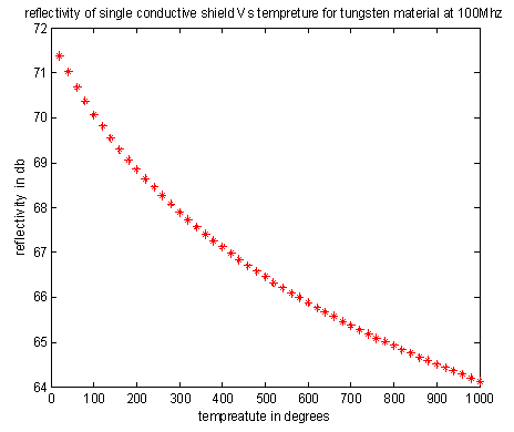 | Figure 5. variation of reflectivity of a tungsten material wit temperature |
 | Figure 6. variation of reflectivity of a iron material wit temperature |
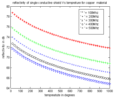 | Figure 7. variation of reflectivity of a copper material with temperature at different frequencies |
 | Figure 8. variation of reflectivity of a aluminum material with temperature at different frequencies |
 | Figure 9. variation of reflectivity of a nickel material with temperature at different frequencies |
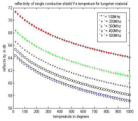 | Figure10. variation of reflectivity of a tungsten material with temperature at different frequencies |
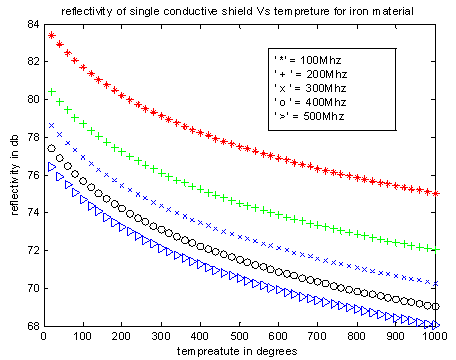 | Figure 11. variation of reflectivity of a iron material with temperature at different frequencies |
5. Conclusions
From the figures it can be concluded that the reflectivity of the conductive materials can be decreases with increases temperature. Figure 2 shows the variation of reflectivity with respect to the temperature for copper shield, the variation of the temperature can be taken in between 20℃ to 1000℃ for these the variation in the reflectivity can be observed from 71..5 to 79. figure 3 shows variation in the reflectivity for aluminum can be varied from 68 to 75.2, figure 4 shows variation in the reflectivity can be varied from 62 to 70.5 for nickel, figure 5 shows variation in the reflectivity can be varied from 64 to 71.5, figure 6 shows variation in the reflectivity can be varied from 75 to 83.5 for iron material. From fig(7) to fig(10) it can be concluded that as the temperature increases reflectivity decreases and as the frequency increases the reflectivity decreases. From the fig(6) iron shows better reflectivity compared with other materials and nickel fig(4) show less reflective properties. At low temperature the shield can reflects maximum incident signal, so the shield can provides good shielding for the designed circuit which is enclosed by it.
References
| [1] | “Evaluating the Resistivity-Temperature Relationship for RTDs and Other Conductors”, IEEE SENSORS JOURNAL, VOL. 11, NO. 5, MAY 2011 |
| [2] | V P Kodali. ‘Engineering Electromagnetic Compatibility, Principles, Measurements and Technologies’, S Chand and Company Ltd, 2000. |
| [3] | C.R. Paul, "Introduction to Electromagnetic Compatibility", John Wiley & Sons, 2006. |
| [4] | Richard.B.Schulz, et.al, ’Shielding Theory and Practice’, IEEE Transactions on Electromagnetic Compatibility, Vol; 30, No: 3, Aug. 1988, pp 187-201. |
| [5] | P.V.Y.Jayasree, et.al, ‘Shielding Effectiveness of Laminated Shields’, Radio Engineering, vol. 17, no. 4, December 2008. |
| [6] | S.M.Yang, et.al. ,’Electromagnetic Shielding Effectiveness of Multilayer Metallic Thin Film on Plastic Substrates’ , Journal of Applied Polymer Science , Vol.110, 1403-1410,2008 |
| [7] | H.-W. Deng, ‘Effective Skin Depth for Multilayer Coated Conductor’, Progress In Electromagnetics Research M, Vol. 9, 1-8, 2009. |
| [8] | S. M. Yang, Y. Y. Chang, ‘Electromagnetic shielding effectiveness of multilayer metallic thin film on plastic substrates’, Journal of Applied Polymer Science, Volume 110, Issue 3, pp. 1403–1410, November 2008. |
| [9] | R. Oussaid, “Study of The Materials Improvement In Electromagnetic Compatibility”, Journal of Electrical Systems Special Issue, No. 01, pp. 53 – 56, November 2009. |
| [10] | C D Raj, G S Rao, et.al., ‘Estimation of Reflectivity and Shielding Effectiveness of Three Layered Laminate Electromagnetic Shield at X-Band’, Progress In Electromagnetic Research B (PIER), USA, Vol. 20, pp. 205-223, 2010. |
 Abstract
 Reference
 Full-Text PDF
 Full-text HTML