Farshad Ghasemi 1, Freidoon Abbasi Davani 1, Mohammad Lamehi rashti 2, Mohammad Mahdi Abbasi 3
1Department of Radiation Applications Engineering, Shahid Beheshti University,Tehran, Iran
2Institute For Research In Fundamental Sciences(IPM) , School Of Particles And Accelerators, Tehran, Iran
3Department of Communications Engineering, Islamic Azad University of South Tehran, Tehran, Iran
Correspondence to: Mohammad Mahdi Abbasi , Department of Communications Engineering, Islamic Azad University of South Tehran, Tehran, Iran.
| Email: |  |
Copyright © 2012 Scientific & Academic Publishing. All Rights Reserved.
Abstract
There are many methods for fabricating electron linear accelerator cavities. In the present research two methods were chosen: first, separable parts (separate ring and disks) and second, parallel disks and cylinder (integrated). The resonance frequencies of cavities and the quality factor of each frequency are two important parameters in their performance. The comparison of measured parameters of the cavities made with two methods, firstly by the network analyzer machine and secondly using the HFSS simulator. The results of both the practical measurements and the simulation of the two structures indicated that the integrated method is better for implementing cavities.
Keywords:
Electron Linear Accelerator, Cavity, Quality Factor
Cite this paper:
Farshad Ghasemi , Freidoon Abbasi Davani , Mohammad Lamehi rashti , Mohammad Mahdi Abbasi , "Implementation of Main Waveguide Cavities of Electron Linear Accelerator Using Integrated and Separable Methods and Comparing Their Performance", International Journal of Electromagnetics and Applications, Vol. 2 No. 6, 2012, pp. 163-168. doi: 10.5923/j.ijea.20120206.05.
1. Introduction
The limitations of electro-static accelerators and the disproportionate largeness of high-voltage generators led the researchers to use other methods for accelerating particles. Using RF and conducting electro-magnetic waves into metal cavities which made a strong electric field allowing charged particles to take the necessary energy, solved the problem and many accelerators were made around the world on this basis[1].Linear accelerators are a type of these accelerators. Linear accelerators are known by the abbreviated term ‘Linac’. The word ‘linear’ has been used for this accelerator in contrast with other kinds of accelerators such as cyclotron and betatron in which particles move in circular directions while being accelerated.Electron Linacs have many usages for industrial, medical and research purposes nowadays such as industrialradiography, treating cancer, producing radiopharmaceutical, sterilization of medical equipments and applied physics. Electron Linacs are divided into two types: Travelling Wave accelerator (TW) and Standing Wave accelerator (SW). Each of these two types has advantages and disadvantages and each has in its turn various types. However, the main part of the accelerator consists of a waveguide in both types.In TW accelerators, the RF wave moves in the direction of the accelerating waveguide and the remaining power of the wave at the end of the accelerating waveguide is absorbed at a suitable resisting load (which exists at the end). In contrast, in SW accelerators, the two ends of the accelerator have been efficiently short-circuited. Hence, the RF power is reflected backward[2].In both types, a series of connected cavities are used. The electro-magnetic energy in each single cavity oscillates sinusoidally in a frequency equal to the resonance frequency of the accelerator. The efficiency of the transition of the input RF power to the electron energy transiting the gaps in SW accelerators is twice as much as that in TW ones.In studies pertaining to physics and high energy beams, TW accelerators are used in particular medical usages which need less physical space and the stability of the beam is important, whereas SW accelerators are more preferable.[2]Hereafter, the constituent parts of electron linear accelerator the travelling wave type are introduced using waveguide cavities methods: 1. Separable parts (separate ring and disks) and 2. Cylinder and parallel disks (integrated). These two methods will also be compared from experimental and simulation viewpoints.
2. The Constituent Parts of a Travelling Wave Accelerator
Fig. 1 represents a simple model of a typical TW electron Linac. The main parts of an electron linear accelerator are: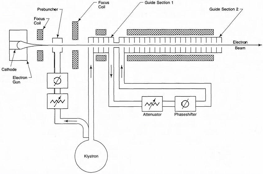 | Figure 1. Simple model of a typical TW electron Linac[2] |
2.1. RF Generator System
The RF system is one of the main parts of an accelerator and has various parts. Since producing electro-magnetic waves requires a high power RF (in Mega Watt measures at peak power), this power is produced by low-width pulses (in micro second measures) and is strengthened by microwave tube amplifiers (such as Klystron). The microwave tube amplifiers need high voltage and high-current pulses which are produced by the power modulator.The modulator and the Klystron constitute the main parts of the RF generator system. The power modulator turns the AC current into high voltage pulses. Its main parts are a high voltage generator, a high voltage pulse unit and a pulse transformer. The Klystron generates high power output RF by amplification of the low power input RF. The produced RF wave is distributed to the cavities by the waveguide system[1].
2.2. Injector
This part has the several roles. First, the production and initial acceleration of the electron beam. Second, initial bunching electrons by pre-buncher cavities. Third, accelerating and bunching electrons so much more in the main buncher so that the electrons are injected to the main tube of the accelerator in harmony with the phase velocity of the RF wave. Forth, narrowing the electron bunches with a narrower energy spectrum[2].
2.3. The Accelerator’s Main Waveguide
This part is in fact a transmission line of the RF wave which consists of a series of cavities. The distribution of electro-magnetic waves in the transmission lines follows Maxwell equations.Though the above divisions for electron Linac, separates the accelerating buncher from the main waveguide, it can be considered the primary part of the accelerating tube. Since this part is in fact a particular transmission line for electro-magnetic waves[1].
3. The Structure of the Main Accelerating Waveguide
Various structures have been designed so far for the main accelerating waveguide but the simplest one used in Linacs is the use of disk loaded structure (based on TM010 mode). In this structure, a cylindrical tube in which there are disks with certain distances is used (Fig. 2). The distance, thickness and substance of the disks and also their interior and exterior diameter are chosen based on the mode. The frequency of the RF wave, the quality factor (Q), the shunt impedance, and the easiest way to fabricate them are measured and evaluated[3] .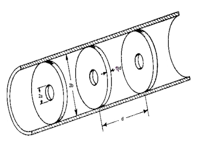 | Figure 2. Disk loaded structure[4] |
4. Materials and Methods
The intense electric fields, which accelerate electrons along the cavity axes, are set up by electric currents flowing on the inner cavity surfaces. There is a simple expression that determines the microwave power P dissipated in inner surfaces of the accelerator guide, which is needed to produce an electron energy gain V. for either a TW or a SW constant gradient accelerator guide. It is  | (1) |
Where Z is the so-called shunt impedance per unit length length and L is the length of the accelerator. The shunt impedance measures the efficiency of the accelerator. Higher shunt impedance means higher electron energy gain for a given microwave power[2].Since the value of shunt impedance is in proportion with the square root of electric conductivity, metals such as copper, silver and gold are appropriate for making cavities [4].Copper was used for fabricating cavities. Among the different kinds copper, OFHC1 is more suitable for making cavities because of its high electric conductivity and its low amount of oxygen.The complete process of designing an electron Linac tube can be followed in Fig. 3[5].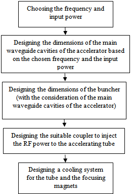 | Figure 3. The process of designing an accelerating tube[5] |
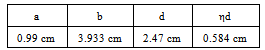
Decision about the frequency must be made by considering the performance of the accelerator and based on available RF generators in different frequency intervals. Moreover, since the frequency determines dimensions of the cavity, some considerations for high (small dimensions) and low (large dimensions) frequencies must be made in fabricating cavities. The frequency of the accelerator under our study was taken at 2998 MHz[5] .Table 1 shows the calculated dimensions in this frequency in which ‘d’, ‘b’, ‘a’, and ‘ηd’ stand for the length of cavity, the radius of the waveguide cylinder, the radius of the opening of the disks, and the thickness of the disks respectively. Table 1. The resulted dimensions for cavities[4]
 |
| |
|
Many building and joining methods have been used for the main waveguide of an electron Linac[1]. Considering the existent facilities, two methods were chosen and executed: The separate parts method (separate ring and disks) and parallel disks and cylinder (integrated) method. The first one is the simplest method. In this method, the set of cavities consists of the disks and rings put together (Fig. 4). The surface of the disks and the interior surface of the rings are smooth and burnished.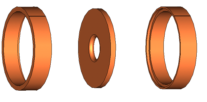 | Figure 4. Fabricating cavities with separate rings and disks |
Fig. 5 shows part of the main waveguide of an electron Linac made by this method. This part which has been made in the Radiation Application Lab of Shahid Beheshti University consists of a set of eight cavities.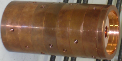 | Figure 5. The structure of disk-loaded with separable ring and disks (made in Shahid Beheshti University) |
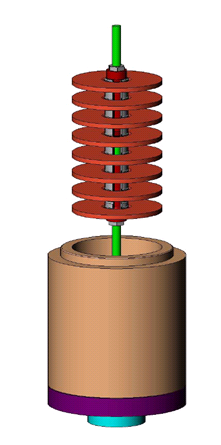 | Figure 6. Fabricating Integrated Cavities |
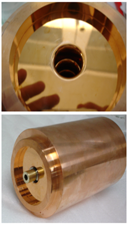 | Figure 7. The fabricated Integrated Set |
The resonance frequency and quality factor of both eight cavity sets were measured by the network analyzer machine and the RF generator (Fig. 8). In both measurements a resonance peak per each cavity was resulted. As an example, Fig. 9 shows the frequency response resulted from of the integrated set. Quality factor was calculated with 3db band-width of transmission function amplitude.The resulted resonance frequency and quality factor for separable and integrated sets are shown in Tables 2 and 3 respectively.The results show that resonance frequencies of these sets are different from each other and for close frequencies; the resulted quality factor for the integrated set is higher.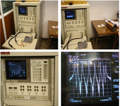 | Figure 8. resonance frequency and quality factor measure by network analyzer machine |
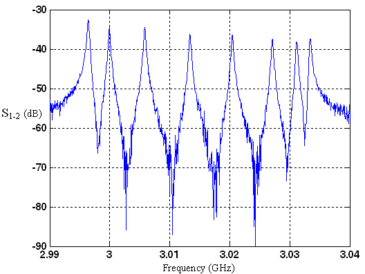 | Figure 9. Frequency response resulted from of the integrated Set |
For instance, for the closest frequency to 2998 MHz (which is our frequency and the designing of the dimensions has been based on it), in the integrated set, we have 3000 MHz frequency and quality factor of 8823. Whereas the separable set has 3001 MHz frequency and quality factor of 7172.| Table 2. The resulted dimensions for separable cavitie |
| | Frequency(MHz) | QualityFactor | | 2986 | 6738 | | 2995 | 7595 | | 3001 | 7172 | | 3004 | 5580 | | 3012 | 6100 | | 3017 | 5716 | | 3022 | 5542 | | 3027 | 5230 |
|
|
| Table 3. The resulted dimensions for integrated cavities |
| | Frequency(MHz) | QualityFactor | | 2996 | 8734 | | 3000 | 8823 | | 3006 | 9393 | | 3013 | 9415 | | 3020 | 8988 | | 3027 | 8902 | | 3031 | 8914 | | 3033 | 8427 |
|
|
5. Simulation
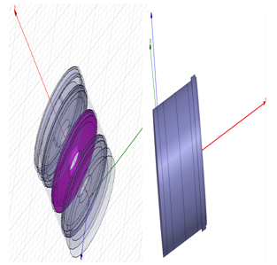 | Figure 10. The simulation of the three cavity set in HFSS |
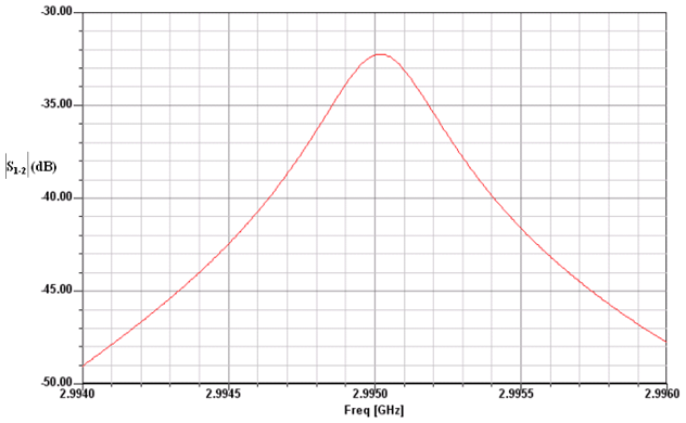 | Figure 11. One resonance frequency peak obtain by HFSS |
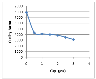 | Figure 12. The Quality Factor in Different Gaps |
To analyze and compare the two methods of designing cavity waveguides of electron Linac, some sets with three cavities of each design were simulated. The simulation was done by HFSS software. HFSS is a software designed for simulating the electro-magnetic behavior of structures in microwave frequency. This software analyses the structure with Finite Element method.At first cavities were defined as separate rings and disks in this software. The distance between them was taken as a parameter so that the integrated cavities can be simulated by taking the amount of this parameter zero. In practice, to join the rings and disks in the separable set, mechanical pressure (bolts and nuts) is used. Hence, by changing the distance parameter from 0.5 µm to 3 µm in the simulation, the effect of the pressure for the ring set and the separate disk can also be simulated (Fig. 10).As an example, Fig. 11 shows the one resonance frequency peak obtain by HFSS.Fig. 12 shows the resulted quality factor for the nearest frequency to the presupposed frequency. It can be seen that when the gap is zero (in the integrated set) the quality factor is much higher than when the cavities have a small gap (in the separable set).
6. Conclusions
The results of the measurements show that in equal conditions (the same materials and dimensions) integrated cavities have a higher quality factor in contrast to separable cavities. The results of the simulation (by comparing the quality factor of zero distance with other states) prove this and show that the integrated design is much better than the separable design. Moreover, the integrated design has the advantages of solving the problem of fluctuation of frequency and creating vacuum more easily in contrast to the separable design.
ACKNOWLEDGEMENTS
We owe a debt of gratitude to Dr. Lamei, Institute for studies in theoretical Physics and Mathematics (IPM) for guiding us through the project.
Note
1. Oxygen Free High Conductivity
References
| [1] | Pierre m. Lapostolle & albert l. Septier. Linear accelerators. North- Holland Publishing Company.1970 |
| [2] | C.J.Karzmark-Department of Radiation Oncology Stanford University School of Medicine. Medical Electron Accelerators. McGRAW hill- New York / 1993 |
| [3] | M.Chodorow, E.L Ginzton, W.Hansen, L.Kyhl, B.Neal And W.K.H Panofsk. Stanford High-Energy Linear Electron Accelerator(Mark III). The review of scientific instrument. VOLUME 26, NUMBER 2/ 1955 |
| [4] | Siamak Nazemi. Design of Main Waveguide Cavities of e-Linac. MSc thesis. Shahid beheshti Univ. Tehran. 2007 |
| [5] | Farshad Ghasemi. Designing and Simulation of a Buncher for e- Linac. MSc thesis. Shahid beheshti Univ. 2009 |
 Abstract
 Reference
 Full-Text PDF
 Full-Text HTML