-
Paper Information
- Next Paper
- Previous Paper
- Paper Submission
-
Journal Information
- About This Journal
- Editorial Board
- Current Issue
- Archive
- Author Guidelines
- Contact Us
International Journal of Electromagnetics and Applications
p-ISSN: 2168-5037 e-ISSN: 2168-5045
2012; 2(6): 159-162
doi: 10.5923/j.ijea.20120206.04
The Radiating Unit Based on Hybrid Metal-Dielectric Structure with Bounded Sequence of Transverse Slots
 Abstract
 Reference
 Full-Text PDF
 Full-Text HTML
Mayboroda D. V. , Pogarsky S. A. , Saprykin I. I.
Karazin Kharkov National University, 4, Svoboda sq., Kharkov, 61022, Ukraine
Correspondence to: Mayboroda D. V. , Karazin Kharkov National University, 4, Svoboda sq., Kharkov, 61022, Ukraine.
| Email: |  |
Copyright © 2012 Scientific & Academic Publishing. All Rights Reserved.
The structure which consists of the five transverse slots based on inverted dielectric waveguide was experimentally investigated. The possibility of creating an antenna on the basis of the above mentioned waveguide with an acceptable radiation pattern and good agreement feed line and antenna are presented.
Keywords: Inverted Dielectric Waveguide, Radiation, Slot
Cite this paper: Mayboroda D. V. , Pogarsky S. A. , Saprykin I. I. , "The Radiating Unit Based on Hybrid Metal-Dielectric Structure with Bounded Sequence of Transverse Slots", International Journal of Electromagnetics and Applications, Vol. 2 No. 6, 2012, pp. 159-162. doi: 10.5923/j.ijea.20120206.04.
1. Introduction
- The development of communications systems,telecommunications and global positioning systems require a constant search for new technical solutions in the designing and creation of multifunctional devices of microwave and SHF bands. Also in telecommunications millimeter waves offer more bandwidth, and this technology is very promising especially for indoor cellular systems. Certainly, the same solutions for basic waveguides and resonators can be used also in the millimeter frequency range. However, there are many peculiarities specific for the millimeter-wave devices that call for more investigations necessary for development and perfection of the new technology. Moreover, devices in this band must possess not only a high level of integral characteristics (the characteristics of the radiation, the possibility of excitation of wave modes with different polarization), but also easy to manufacture an acceptable tolerance, ease of excitation and concordance with external circuits.Such a set of requirements significantly satisfy the hybrid metal-dielectric structures (HMDS) made on the basis of various modifications of dielectric waveguides [1-4]. Among them, more and more attention is attracted by the so-called inverted dielectric waveguide (IDV), due to the fact that the IDV have some unique features not only in terms of physics of electromagnetic wave propagation, but also the structural features, in particular, the ability to create low-profile designs with branched topology.To create a high-performance millimeter-wave radiating systems can be used HMDS with single (or sequences) slot discontinuities, one of the options is considered in the paper.
2. Basic Design
- As a basic construction the HDMS based on IDV was selected. Schematic representation of the radiating structure is shown in Figure 1. In this figure: 1 – segment of microstrip conductor, 2 – dielectric slab, 3 – dielectric rod, 4 – grounded base, 5 – slot discontinuity of rectangular shape. The elements of design had the following parameters: dielectric rod had dimensions
 =6.8×3 mm and was made of polystyrene with
 , the dielectric substrate was made of alumina
 , with dimensions 60x48x0.5 mm, the length of microstrip had the width of 6 mm . The axis of slot radiator with the size of
  =4×1.5 mm is oriented perpendicular to the axis of a dielectric rod (the direction of propagation of the eigenwave). Excitation was carried out by the method which is described in [4].
 | Figure 1. The schematic view of the structure |
 GHz the failure in the characteristic of attenuation is observed while the value of VSWR is less than the level of 1.5. Exactly the effective radiation from the structure may be predicted near this frequency.
 | Figure 2. The attenuation and VSWR characteristic versus frequency  |
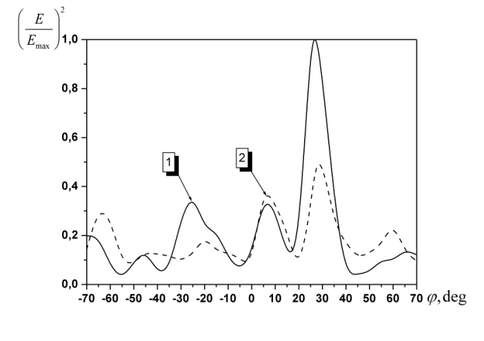 | Figure 3. The normalized pattern characteristics   |
 GHz, the curve corresponds to the frequency
  GHz. In both cases the shift of the maximum radiation from the normal is observed, but in the resonance case, one can detect the main lobe clearly (in this case
  , where s is the length of the slot,
  is the wavelength in HMDS). One can predict that reducing of spurious lobes may be achieved by increasing the quantity of radiators and optimizing the conditions of excitation of the structure.
3. Radiating Unit
- Investigated basic design has been modified to improve electrodynamical performance. One of these modifications consists in use bounded periodical sequence of transverse rectangular slots in auxiliary microstrip conductor. And the second one consists in improving of excitation technique of basic structure (IDV). Schematic representation of the radiating structure is shown in Figure 4.
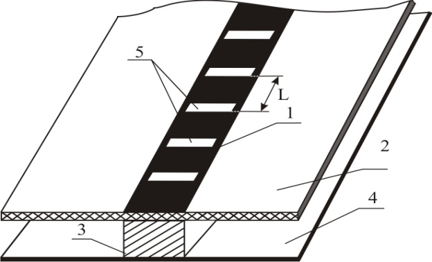 | Figure 4. The schematic view of radiating unit |
 mm, the distance between radiators were
  mm. This distance with taking into account wavelength shorting factor approximately equals to the wavelength in the structure. It is well known that effective radiation may be realized including under the condition of effective excitation of the basic structure (IDV). The best known method of excitation of such structures suggests that part of the dielectric rod is introduced into a rectangular waveguide. In this case the shape of the inputted into the waveguide part of rod and its length is very essential. These parameters will determine the level of insertion loss and the level of concordance with external circuits. Experimentally a lot of shapes of termination part of the rod have been investigated. In comparing with widely used shape in the form of ordinary scarf with Brewster’s angle along narrow side of the rod [5] the pyramidal and semi- pyramidal shapes are more attractive because they provide lowest level of attenuation and higher level of concordance with external circuits.
 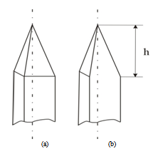 | Figure 5. The shape of termination part of the rod |
 the submerged length is optimal when
  , where
  is wavelength in complicated structure.In Figure 6 the attenuation and VSWR characteristics versus frequency are presented. The curve 1 reflects the dependence of magnitude attenuation, curve 2 shows the dependence of the level of VSWR versus frequency. As it is evident from the figures the curve 2 have a lot of oscillations, which is caused by the influence of slot discontinuities on the wave propagating in the channel, but in certain frequency band (28-30 GHz) it is observed frequencies within which the VSWR is about the level of 1.75…1.85. It may be predicted that in this band it is possible to obtain effective radiation from the structure.
  | Figure 6. The attenuation and VSWR characteristics versus frequency  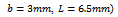 |
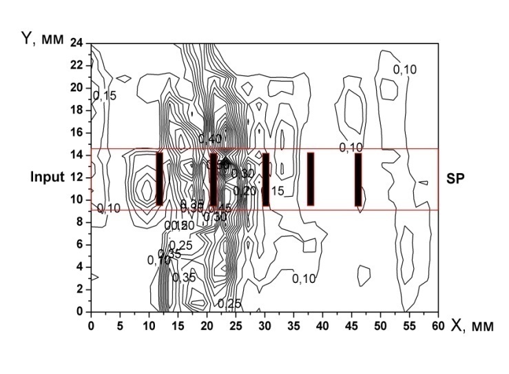 | Figure 7. The near field structure at 30.18 GHz  |
 | Figure 8. The pattern characteristics of the structure at different frequencies   |
4. Conclusions
- Thus, the carried out experimental researches show that the using of an alternative transmission line, for example inverted dielectric waveguide, allows to design thefunctional elements with high level of integral characteristics.