Ahmed Hossam-Eldin , Wael Mokhtar , Ehab Mohamed Ali
Electrical Engineering department, Faculty of Engineering, Alexandria University, Alexandria, 21511, Egypt
Correspondence to: Ehab Mohamed Ali , Electrical Engineering department, Faculty of Engineering, Alexandria University, Alexandria, 21511, Egypt.
| Email: |  |
Copyright © 2012 Scientific & Academic Publishing. All Rights Reserved.
Abstract
This paper investigates the interference between electromagnetic field produced by high voltage power lines and living organisms and metallic objects underneath the transmission lines such as ships, at rivers crossing, and vessels passing under or near to power lines. Metallic pipelines buried in the same corridor are affected with many factors, namely: the power line configuration, separation distance between transmission line and pipeline, separation distance between conductors, the transmission line tower height, existence of the earth wire, the sequence of the power supply, the length of corridor and the fault conditions. The equations of magnetic fields of the transmission lines and the density of currents induced in the human bodies and metallic ships surface were introduced. The induced voltage on the neighbouring pipelines was calculated. A computer program was developed to model and simulate the magnetic fields produced by power lines. The program calculates the current density induced in objects underneath or in the neighbourhood of the transmission line. The results obtained using the developed program illustrated to be consistent with previous literature results. The obtained results showed to be satisfactory and consistent with the experimental ones.
Keywords:
Human Bodies, Electromagnetic Fields, Metallic Objects, Power Line
Cite this paper:
Ahmed Hossam-Eldin , Wael Mokhtar , Ehab Mohamed Ali , "Effect of Electromagnetic Fields from Power Lines on Metallic Objects and Human Bodies", International Journal of Electromagnetics and Applications, Vol. 2 No. 6, 2012, pp. 151-158. doi: 10.5923/j.ijea.20120206.03.
1. Introduction
It is common that electromagnetic fields produced by transmission lines causes dangerous effects on both living organisms and any metallic objects. If the human bodies are projected to high levels of magnetic fields the main effect of interferences is the production of electric currents within the body. Electric and magnetic fields differ, in their effects, when they pass across the body of living organisms at low frequencies. An electric field directed on an unshielded person discharges to ground while the magnetic field permeates the body inducing a magnetic flux that generates secondary electric fields inside the body and then induce currents density that causes a change in protein, DNA syntheses, enzyme activity, heart dysfunction and possible nervous effects. While metallic structures near to transmission lines are subjected to interference arising from inductive, capacitive and resistive coupling as in[1]. Inductive coupling arises when the structure is placed in a time varying magnetic field. Capacitive coupling only affects structure located above ground since these have a capacitance to both the transmission line and to the earth as in[2,3]. Resistive coupling between a transmission line and metallic pipeline is only relevant during ground fault when significant levels of currents flow into the ground.This interference with metallic objects causes corrosion of the object material or risks for people entering in contact with this objects. In case of cathodic protection of metallic objects magnetic interference may produce mal-operation. This paper studies the inductive interference to the human bodies and metallic objects and the factors affecting the interference. It simulates the process using the developed computer program.
2. Theoretical Analysis
2.1. The Magnetic Field Density Produced from Power Lines
2.1.1. A 500 kV Horizontal Configuration
This line consists of three conductors lying on the horizontal plane. Using the centre conductor as the reference point o, s is the distance of the two other conductors from centre line and I is the conductors current. The magnetic field density B in Tesla can be found as in (1),[4]. | (1) |
Where R is the distance from any point of interest and the centre point of power line o, r is the angle between the vector R and the horizontal central line as shown in figure.1.a.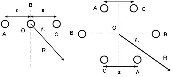 | Figure 1. Conductors arrangement on transmission lines, (a) Horizontal single circuit configuration (b) Double circuit configuration |
2.1.2. A 220kV Double Circuit Line Configuration
This configuration is considered as a low reactance double circuit line with balanced and equal currents on the two circuits as shown in figure.1.b.The magnetic field density B in Tesla can be found as in (2),[4]. | (2) |
2.2. The Induced Electric Field and Current Density
For any structure may be considered as a homogeneous cylinder, the magnetic field will induce an electric field E in the structure, according to Faradays law, is given as in (3),[5,6]. | (3) |
Wherer: radial distance from the centre of the cylinder to the point where E is evaluated.E: vector lines in a plane perpendicular to B and is oriented tangentially to circles of radius r. | (4) |
For the structure conductivity σ the current density J in A/m2 can be found as in (5), (6),[5]. | (5) |
 | (6) |
2.3. Induced Voltage on Pipeline
The mutual impedance with earth return in Ω/m between pipeline and phase conductors of transmission line, which carry an ac current of frequency 50 Hz, can be found using Carson’s formula as in (7). where δ in meter is the depth of the earth return path with soil resistivity ρ in Ω.m, space permeability μo, angular frequency ω and distance between pipeline and phase conductors Dph-p can be found as in (8),[7]. | (7) |
 | (8) |
Two conditions can be considered:1. Without overhead earth wire - At normal conditions: The induced voltage Vp on pipeline due to full load currents IA,IB,IC with mutual impedances between phases A,B and C and pipeline ZAP,ZBP,ZCP is given as in (9),[8]. | (9) |
At fault conditions: The induced voltage Vp on pipeline due to fault current Ifault for a single line to ground fault is given as in (10),[9]. | (10) |
2. With overhead earth wire - At normal conditions: The impedance of earth wire with earth return ZE for the earth wire resistance RE and geometric mean radius of RGM is given as in (11),[7]. | (11) |
The mutual impedance between the phase conductor, earth wire and the pipeline is given as in (12),[9]. | (12) |
Then the induced voltage Vp on the pipeline is given as in (13),[9]. | (13) |
At fault conditions: Considering earth wire at fault conditions there are a shielding factor K that can be found as in (14),[9]. | (14) |
The induced voltage Vp on the pipeline at fault condition is given as in (15),[9]. | (15) |
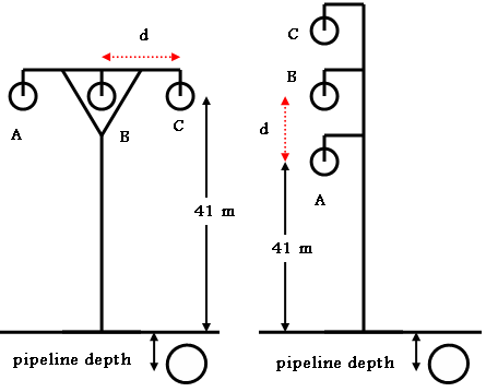 | Figure 2. Different interference system with (a) Horizontal, (b) Vertical |
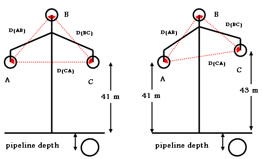 | Figure 3. Different interference system with (a) Triangle equilateral, (b) Triangle with different spacing configurations |
3. Simulation and Modeling of System
3.1. Magnetic Field Density from Power Lines
3.1.1. A 500 kV Horizontal Configuration
According to The separation distance between conductors of s=11m, the height of tower is h=37.5m and the conductor current of I=650A.then by using equation (1) the magnetic field density can be seen in figure.4. | Figure 4. Magnetic field density from 500kv horizontal configuration |
3.1.2. A 220kV Double Circuit Power Line Configuration
According to The distances between conductors s=6m, height of tower h=41m and the conductors current I=1000A. Then by using equation (2) the magnetic field density can be seen in figure.5. | Figure 5. Magnetic Field Density From 220kV Double Circuit Configuration |
Figures. 4,5. show that the magnetic flux density produced from 220kV double circuit line configuration is less than that from 500kV horizontal configuration single circuit. This is due to the fact that the magnetic field produced from each conductor of the double circuit will be balanced by other ones. This will reduce the net magnetic field seen by any object.
3.2. Current Density Induced in Human Body
The current density in A/m2 induced due to electric field which is produced from the magnetic field can be determined using equation (6). For a person having a head of radius=0.1m and body of radius=0.3m and body conductivity σ=0.2 S/m, the current density for different distances from the 500kV horizontal single circuit transmission line can be seen in figure.6.The results of current density for different distances from 220kV double circuit transmission line can be seen in figure.8.Figures. 6,8 show that the induced current density on human body in case of single circuit is greater than that of a 220kV double circuit. This is due to the magnitude of magnetic field density. | Figure 6. Induced current in human bodies due to 500kV power line |
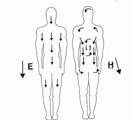 | Figure 7. The Human electric and magnetic field |
 | Figure 8. Induced current in human bodies due to double circuit power line |
3.3. Induced Current on Metallic Ships and Vessels Underneath Power Line
By applying the same method on ships and vessels such as missile boats of radius=9m, destroyer of radius=29.5m, cargo of radius=23.5m, frigate of radius=11.5m and Aircraft carrier ships of radius=47.5m which are subjected to electromagnetic fields from 500kV horizontal single circuit power lines crossing over rivers or canals with s=11m, h=140m, I=650A and the conductivity of metallic material σ=0.3*106 S/m the results of current density can be seen in figure.9. | Figure 9. Induced current in ships surface due to horizontal power line |
By applying this method on ships and vessels which are subjected to electromagnetic field from 220kV double circuit power lines crossing over the rivers with s=6m, h=140m and I=1000A the results of current density can be seen in figure.10. | Figure 10. Induced current in ships surface due to double circuit power line |
Figures. 9, 10 shows that induced current density on ships and vessels under or near to high voltage power lines are subject to high amount of current density. Fortunately these currents can be dissipated in the earth water the ships or vessels is navigating in. the larger the surface area of that ship (hull) the quicker the dissipation of current.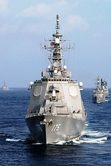 | Figure 11. The destroyer ships as a homogeneous cylinder |
3.4. Interference with Pipelines and the Factors Affecting It
3.4.1. Power Line Configuration
The induced voltages on pipelines are significantly dependent on the configuration of the power line. The electromagnetic fields produced by the overhead line phases, generally balance each other and significantly reduce the net field seen by the pipeline and then affect the magnitude of the induced voltage on pipeline[10].Figures. 2, 3 show different configurations of 220 kV, transmission line with a phase current I=1000A at normal conditions, distance between conductors d=6m, length of parallelism of pipeline L=10km and soil resistivity of 100 Ω.m.Figure. 12 shows that the vertical configuration caused the height magnitude of induced voltage for the first 40m separation distance between the centre of power line and the pipeline than any other configuration[11]. This is due to the high density of the resultant electromagnetic field EMF produced from the vertical power line than the others and still has the higher magnitude than the delta configuration until reaches 80m. Then as we move laterally away from the centre, the vertical configuration gives the lower magnitude of induced voltage than the other configurations; the delta configuration causes a medium value of induced voltage between vertical and horizontal configurations. | Figure 12. Different power line configurations |
It can be seen that the horizontal configuration caused a smaller amount of induced voltage, from 0m to 25m separation distance. From 40m although its value decays with increasing distance but it is higher than all other configurations.
3.4.2. Distance Between Power Line and Pipeline
Figure. 12 illustrated that, for all configurations, as the separation horizontal distance from power line increases the magnitude of the induced voltage on pipelines decrease.
3.4.3. Distance Between Conductors
 | Figure 13. Different separation distance between conductors for horizontal configurations |
1- For a 220 kV horizontal configuration - The induced voltages on pipelines, for different separation distance between conductors as d = 4m, 6m and 8m, is indicated in figure.13.2- For a 220 kV vertical configuration - The induced voltage on pipeline was calculated for different separation distances between conductors d = 4m, 6m and 8m is shown in figure.14. | Figure 14. Different separation distance between conductors for vertical configurations |
It can be concluded that as the separation distance between lines increase the induced voltage increases for any configurations. This is due to the fact that the outer phase gets nearer to the pipeline which enhances this phenomenon. Also, it may be due to the fact that the mutual effect of the two neighbour conductors is reduced as they get separated from each other.3- For a 220 kV delta configuration - For the 3-phase 220 kV delta configuration there are two configurations triangle equilateral and triangle which has different spacing as shown in figure. 3.a,b. | Figure 15. Different separation distance between conductors for delta configurations |
Figure. 15. indicated a symmetrical curve at the centre line of the power line for the triangle equilateral configuration. The triangle which has different spacing shows the height of the hump of the curve at the left hand side is higher than that at right hand side.This is because when the pipeline was placed at left side of power line it is more affected by phases A and B which C is much more far out of it, which has a separation distance of 6m. When it is placed at right hand side of the power line it is more subjected to phases C and B, with separation distance of 4.3m.
3.4.4. Height of Towers
For the studies 220 kV horizontal system with d=6m and the height of tower is h=41m, 38m and 35m. Figure. 16 shows that as the height of the tower increases the net electromagnetic field EMF seen by the pipeline decreases, then the induced voltage on pipeline decreases. This is the general trend for all power line configurations. | Figure 16. Different height of towers for horizontal configurations |
3.4.5. Existing of the Over Head Earth Wire OHEW
 | Figure 17. Power line with and without OHEW |
The OHEW will break the magnetic field balance of the system and leads to higher induced voltage on the pipeline at normal condition[9].• Triton 37/3.75 AAC which has RGM of 0.00982m and resistance of 0.0869 Ω /km can be using as OHEW.As the resistance of earth wire increases the mutual impedance increases according to equation (12). And then the total induced voltage increases according to equation (13) this is consistent with figure. 17.
3.4.6. Sequence of the Power Line Phases
The phase sequence of three phases, with earth wire affects directly the height of the maximum induced voltage value, depending on the position of the pipeline, this is clear in figures 17, 18. for positive sequence of the phases (ABC) if the pipeline is situated at right of the power line the induced voltage on the pipeline is different from that if it was situated at left hand side of power line for the same distances as shown in figure. 17. While for negative sequence of the phases (ACB) the induced voltage on pipeline is the opposite to the positive sequence case as shown in figure. 18. | Figure 18. Power line with and without OHEW |
3.4.7. Length of System Parallelism
The magnitude of induced voltage on pipeline is affected by the parallelism section of the pipeline and power line.For the same 220 kV horizontal configuration the separation between pipeline and power line is 50m and the length of system parallelism are L=5km, L=10km, L=20km and L=30km.The maximum induced voltage occurs at the two ends of the pipeline because of the strong discontinuity of the EMF at these two points and the minimum induced voltage occurs at the midpoint of pipeline because the induced EMF in the pipeline on both sides of this point has the same magnitude and of opposite direction resulting in a minimum induced voltage on this point. Figure. (19) shows the induced voltage along the pipeline for different length of parallel section. As the parallel section increases, the induced voltage on pipeline increases too [12,13]. | Figure 19. Different length of system parallelism |
3.4.8. Fault Conditions
For any configuration the fault condition causes higher induced voltage on pipeline according to the magnitude of the Ifault = 5000A as in[14].Under the fault condition the existence of the OHEW will reduce the impact on the induced voltage on the pipeline due to the resistance of the OHEW affects directly the value of the induced voltage as in[15]. This is attributed to the size of the conductor. The OHEW with large size induces the smallest voltage. This can be verified using the different types of OHEW as in[9]:1. Triton 37/3.75 AAC with RGM of 0.00982m and resistance of 0.0869 Ohms/km.2. Pluto 19/3.75 AAC with RGM of 0.00676m and resistance of 0.168 Ohms/km.3. Leo 7/2.5 AAC with RGM of 0.00244m and resistance of 1.02 Ohms/km. | Figure 20. Power line at fault condition |
From figure.20, it is clear that the triton OHEW produces the least induced voltage and vice versa.
4. Conclusions
This paper has explained and analysed the interference between high voltage transmission lines and human bodies, metallic ships and pipelines which have different factors that affect the interference. Modelling and simulation of induced current density on human bodies, metallic ships surface and the induced voltages on pipelines for various configurations of power lines is investigated. The magnetic field of over head transmission line with different configurations was determined using Ampere law.A computer program was developed to calculate the values of the induced current density and induced voltages. This developed program showed to be very effective and with least running time. This method was compared with the results obtained using EMTP and showed to be more accurate and having a smaller running time. The electromagnetic field interference is significantly dependent on the power line configurations, separation distance between transmission line and objects underneath, separation distance between conductors of transmission line, the transmission line tower height, existence of the earth wire, the sequence of the power supply, the length of system parallelism and fault conditions.
ACKNOWLEDGEMENTS
First of all, I would like to thank my GOD for giving me the ability to complete my work.My deepest gratitude goes to my supervisor Prof. Dr. Ahmed A.Hossam-Eldin for his keen academic advice, constant encouragement, guidance, and support during my work.I would also like to thank Dr. Wael Mokhtar for his encouragements and help.My sincere regards goes to my mother and my father for all their help and care along all my whole life.I would like to sincerely thank my wife and my daughters, Gody and Lamar for their endless love, support and understanding.
References
| [1] | Bander Jubran Al-Gahtani, Electromagnetic Interference Caused By A High Voltage Transmission Network On Burned Pipeline And Communication Cables, thesis, king Fahd university of petroleum and minerals, Saudi Arabia, 2009. |
| [2] | Hanafy M. Ismail, Effect of Oil Pipelines Existing in an HVTL Corridor on the Electric-Field Distribution, IEEE TRANSACTIONS ON POWER DELIVERY, VOL. 22, NO. 4, pp.2466-2471, 2007 |
| [3] | Mohamed M. Saied, The Capacitive Coupling Between EHV Lines and Nearby Pipelines, IEEE TRANSACTIONS ON POWER DELIVERY, VOL. 19, NO. 3, pp.1225-1231, 2004 |
| [4] | George Filippopoulos and Dimitris Tsanakas , Analytical Calculation of the Magnetic Field Produced by Electric Power Lines, IEEE TRANSACTIONS ON POWER DELIVERY, VOL. 20, NO. 2, pp 1474, APRIL 2005. |
| [5] | A.A.Hossam-Eldin, Kamilia Youssef and Hanna Karawia, investigations of induced currents in human bodies due to exposure to EMF from low voltage appliances, 11 inter Middle East power systems conference, December, 2006. |
| [6] | M. Trlep, A. Hamler, M. Jesenik, and B. ˇStumberger, Electric Field Distribution Under Transmission Lines Dependent on Ground Surface, IEEE TRANSACTIONS ON MAGNETICS, VOL. 45, NO. 3, pp.1748-1751, 2009. |
| [7] | Jurgen Schlabbach, short circuit current, Institution of engineering and technology, pp.245, 2008. |
| [8] | Ghada M. Amer, Novel Technique To Calculate The Effect Of Electromagnetic Field Of H.V.T.L. On The Metallic Pipelines By Using EMTP Program, 18th International Conference on Electricity Distribution, pp2, Egypt, 2005. |
| [9] | M. Nassereddine and A. Hellany, AC interference study on pipeline, the impact of the OHEW under full load and fault current, 2 Inter. Conf. on Computer and E.E, paper number IEEE DOI 10.1109/ICCEE.2009.139, pp.497-501. |
| [10] | M. H. Shwehdi and U. M. Johar, Transmission Line EMF Interference with Buried Pipeline: Essential & Cautions, Proceedings of the International Conference on Non-Ionizing Radiation, pp2, 2003. |
| [11] | E. Sawma, B. Zeitoun, N. Harmouche, S. Georges and M. Hamad, Electromagnetic Induction in Pipelines Due to Overhead High Voltage Power Lines, International Conference on Power System Technology, pp 3, 2010. |
| [12] | A.A.Hossam-Eldin and W. Mokhtar, Electromagnetic interference between electrical power lines and neighboring pipelines, 19th International Conference on system engineering ICSEng,19-21 August LAS VEGAS, USA, 2008. |
| [13] | Konstantinos Kopsidas, and Ian Cotton, Induced Voltages on Long Aerial and Buried Pipelines Due to Transmission Line Transients, IEEE TRANSACTIONS ON POWER DELIVERY, VOL. 23, NO. 3, pp 1535-1543, 2008 |
| [14] | Denisa Stet , Dan D. Micu , A. Ceclan , Laura Darabant , Mihaela Plesa, The study of the Electromagnetic Interferences between HV Lines and Metallic Pipelines using a Professional Analysis Software, 2ND INTERNATIONAL CONFERENCE ON MODERN POWER SYSTEMS, pp335, 2008. |
| [15] | Georgios C. Christoforidis, Dimitris P. Labridis, Senior, and Petros S. Dokopoulos, A Hybrid Method for Calculating the Inductive Interference Caused by Faulted Power Lines to Nearby Buried Pipelines, IEEE TRANSACTIONS ON POWER DELIVERY, VOL. 20, NO. 2 , pp1465-1473, 2005. |
 Abstract
 Reference
 Full-Text PDF
 Full-Text HTML