Mohamed Hayouni 1, Fethi Choubani 1, Tan Hoa Vuong 2, Jacques David 2
1Innov’COM, Sup’ COM, University of Carthage, Tunisia
2ENSEEIHT (France)
Correspondence to: Mohamed Hayouni , Innov’COM, Sup’ COM, University of Carthage, Tunisia.
| Email: |  |
Copyright © 2012 Scientific & Academic Publishing. All Rights Reserved.
Abstract
In this paper, antenna ultra wideband enhancement by non-uniform matching and half-guided wavelength circular embedded slots is presented and analysed in detail. A printed compact rectangular monopole antenna with two convex circled corners has been analysed firstly. A good impedance matching is achieved in the IEEE radar engineering X-band satellite communications by lowering below -50 dB value at 9.5 GHz. The current density can reach 52 A/m with convex corners; this value is large compared to 32 A/m obtained with stepper corners. In addition, the measured radiation patterns at various frequencies show clearly that the antenna displays nearly an omnidirectional radiation pattern in the E plane (xz) and the H-plane (yz) in both co-and cross-polarizations. The group delay indicates that this antenna is reliable so that a transmitted signal will not be seriously distorted. Two circular half-wavelength slots are embedded in the radiating patch to improve S11 in the WLAN band. Accordingly ultra-wideband behaviour is achieved along a bandwidth is ranging from 3.5 GHz to 12.5 GHz. Due to its compact size of 30 x 35 mm2 and its good impedance matching especially in the X band, the designed antenna is able to satisfy some of the requirements of an airborne SAR and is also well suited for remote sensing applications.
Keywords:
Compact Printed Monopole Antenna, Half-Wavelength Circular Slot, Non Uniform Impedance Matching, Ultra-Wideband (UWB)
Cite this paper: Mohamed Hayouni , Fethi Choubani , Tan Hoa Vuong , Jacques David , Design and Analysis of a Compact Printed UWB Antenna Using Non Uniform Matching and Half-Wavelength Circular Slot, International Journal of Electromagnetics and Applications, Vol. 2 No. 6, 2012, pp. 145-150. doi: 10.5923/j.ijea.20120206.02.
1. Introduction
Since the approval and allocation of the frequency band between 3.1-10.6 GHz[1], miniaturization and bandwidth enhancement become one of the most promising technologies for future high-data rate wireless communication, high accuracy radar and imaging systems. Eventually, the UWB system, the UWB antenna has drawn heavy attention from researchers. Some developments in allied branches are now being investigated to antennas applications. Various recent basic principles of broadband design are deployed in the literature. Indeed, the investigation into the performance of proximity coupled stacked patches by the exploration of the relationship required between the dielectric layers, the dimensions of the stacked radiators and the relative location of the feed can achieve a broadband behaviour in excess of 20% as studied in[2]. The optimization of the impedance matching through narrow cavity backed configuration as described in[3],can enhance the bandwidth of the proposed antenna to more than 40% (VSWR<2) since it can provide a larger effective coupling as compared with the conventionalproximity-coupled antenna without a narrow cavity backed configuration. A low Q factor of the magnetic wall under the patch created by a low dielectric constant or larger thickness of the substrate is also an available broadband technique[4]. The impedance matching of the feed by probe compensation using L-shape probe and any reactive loading as evoked in[5] is also another basic principle of broadband design. In addition by integration slots in the ground plane of microstrip planar antennas as deployed in[6]-[7], or by using a rigged ground plane[8] or slots in the radiator as published in[9]-[12], compact operation with enhanced impedance bandwidth can be obtained. In[13] a printed monopole antenna consisting of a square ring radiating patch with a pair of T-shaped strips protruded inside the square ring and a coupled π–shaped and a ground plane with a protruded strip, provides a wide usable fractional bandwidth of more than 130%. In addition some integrated bandstop filters connected to the UWB antenna are used to reject some narrow bands in order to confront a possible electromagnetic interference, as over the allocated wide bandwidth of the UWB system. The use of U, C and H and semi-circular half wavelength slots embedded in the radiator can reject some narrow bands[13],[14]-[15]. However, S11 of the most UWB published designs remains modest (upper -27dB).In this paper we propose an ultra wide band antenna enhancement by non uniform matching. Indeed, a rectangular shaped planar antenna with convex circled corners is investigated in order to excite different electric lengths with smoothly variations. The latter are adjusted to lessen the VSWR between the main resonance frequencies of the rectangular partial grounded patch antenna. A surface current distribution comparison at certain frequencies with the prototype proposed in[9] with stepper corners will be analysed in order to interpret the high impedance matching created between the microstrip feed line and the load in order to prove the efficiency of non-uniform patch profiles. Small circular half-wavelength embedded slots, instead of semi-circular slots used in[16] to reject some narrow bands, are embedded to improve matching (lower S11) at desired frequencies.
2. Configuration A
2.1. Antenna Design
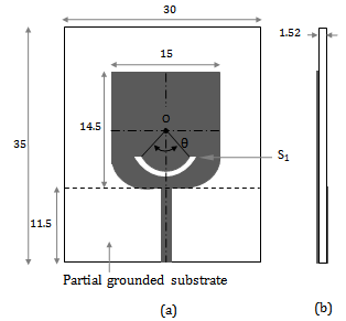
A compact printed microstrip-fed monopole antenna is presented in figure 1. The design is a transfer from the configuration published in[9] with stepper corners to non uniform geometrical corners. It consisted of a rectangular shaped perfect electric conductor printed on a partial grounded FR4 epoxy dielectric substrate of 4.32 permittivity, 1.52 mm thick, 35 mm length and 30 mm width dimensions. At two corners of the rectangular printed monopole, two quarters of disk are inserted. The radius of each convex arc is designed by r. The entire radiating element has a compact size of 14.5 x 15 mm². It is fed through a 50 Ω microstrip transmission line.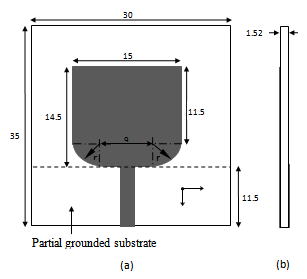 | Figure 1. Configuration A: (a) top view (b) side view (unit: mm) |
2.2. Influence of the Convex Corner Radius on the Impedance Matching
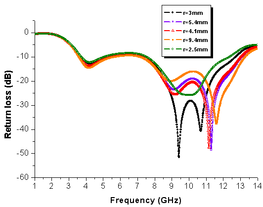 | Figure 2. Return loss coefficient of the rectangular shaped planar antenna with two convex circled corners for various radii |
Several electromagnetic simulations versus r were performed in order to study its impact on S111the impedance matching. Indeed, as depicted by figure 2, we note a good impedance matching in the IEEE radar engineering X band range since the return loss can reach -50 dB at 11.25 GHz for r=5.4mm and is less than -50dB at 9.5 GHz for r=3 mm. The best result that corresponds to the best impedance matching corresponds to r=3 mm radius.
2.3. Current Density
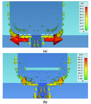 | Figure 3. Simulated current distributions at 11 GHz on the rectangular patch antenna with: (a) two convex circled corners of r=3 mm and (b) stepper corners |
The current distribution normally gives an insight into the physical behaviour of the antenna. In simulation, antennas with stepper and convex circled corners are investigated at various frequencies. Indeed, figure 3 shows the current distribution at 11 GHz frequency supporting our argument of the convex circled corners geometry contribution in the impedance matching in IEEE radar engineering X band range compared to stepped two corners contribution. Higher current density can be observed at the two convex circled corners of the UWB radiator that reaches 52 A/m. This current density value is higher than the current density at the stepper corners radiator presented in[9] that doesn’t exceed 32.5 A/m at the same frequency. It is obvious that the input power is much more efficiently sent to the radiator when using two convex corners. This supports the importance of non uniform geometry such as convex circled geometry inserted between the feed line and the antenna as a good impedance matching mean.
2.4. Results and Discussion
2.4.1. S Parameters
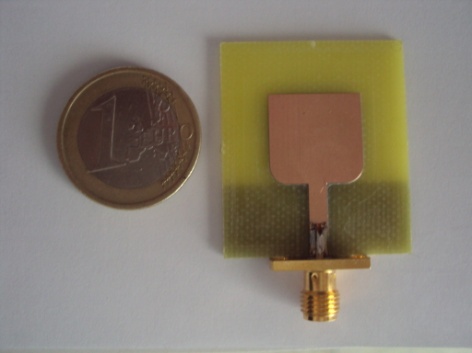 | Figure 4. Top view of the fabricated rectangular patch with two inserted convex circled corners of r=3 mm |
Figure 4 shows the final design of the antenna, along with a photograph of the fabricated prototype. It is measured using a vector network analyzer Anritsu 37369C (40MHz to 40 GHz) where the calibration plane is the SMA connector jack used to connect the antenna. 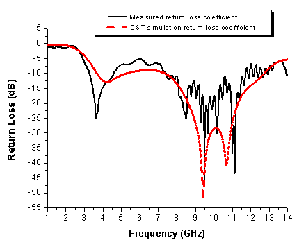 | Figure 5. Return loss of the rectangular patch with two inserted convex circled corners of r=3mm |
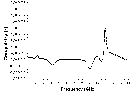 | Figure 6. Group delay |
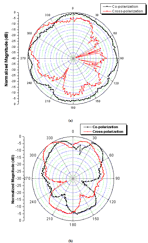 | Figure 7. Normalized measured radiation patterns of the proposed UWB antenna at 3.5GHz: (a) E-plane; (b) H-plane |
2.4.2. Group Delay
The group delay is another critical parameter for ultra wideband antenna, which measures the time signal distortion introduced by the antenna. The simulated result shows that the group delay calculated between two identical prototypes in the whole working band is stable especially from 1 GHz to less than 11 GHz (less than 0.4ns). A slight variation at 11 GHz is acceptable since it doesn’t exceed 1.3ns. In other words, the result indicates that this antenna is reliable so that a transmitted signal will not be seriously distorted by the proposed antenn.
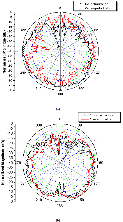
2.4.3. Radiation Pattern
Plots of figures 7–9 show the normalized measured radiation patterns at three individual frequencies 3.5, 5.8, and 11 GHz respectively of the fabricated antenna. It is seen that the radiation pattern is stable. It is almost uniform (nearly omnidirectional) at E and H planes in both co- and cross-polarization for the selected in-band frequencies. At 3.5 GHz and 5.8 GHz frequencies, the E-plane radiation patterns are split into a few radiation beams. This undesired phenomenon can’t be abolished in physics and also exists in many other UWB antennas especially planar monopole antenna[16].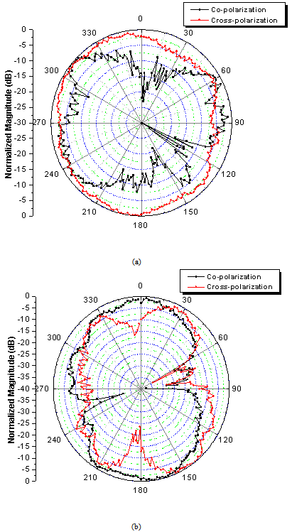 | Figure 8. Normalized measured radiation patterns of the proposed UWB antenna at 7.5GHz: (a) E-plane; (b) H-plane |
 | Figure 9. Normalized measured radiation patterns of the proposed UWB antenna at 11GHz: (a) E-plane; (b) H-plane |
 | Figure 10. Configuration C: (a) top view (b) side view (unit: mm) |
3. Impedance Matching Improvement in the WLAN Band
3.1. Configuration B
Various recent basic principles of impedance matching are deployed in the literature such as the optimization of the impedance matching through an embedded slot in the radiator. Nevertheless, in order to notch the WLAN band, a semi-circular slot embedded in the printed antenna is used in[15]. In designing the slot, the authors used the guided wavelength , where λ0 is the free space wavelength and
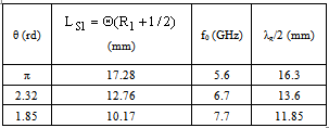
  However, in the rest of this article, we have studied the effective length reduction effect of the circular slot, by maintaining the same radius value during all simulations, on the impedance matching. As depicted by figure 10, the circular slot inserted in the antenna of the configuration B is not semi-circular; it is a portion of a circular slot defined by the θ angle. Indeed, for R= 5 mm, both figure 11 and table1 describe and resume the θ angle variation effect on the notched band frequency and S11. It is clear that as the effective length decreases the notched band shifts to higher frequencies and S11 (dB) decreases. We note that with an effective length equal to 7,09 mm, the notched band disappears and the antenna becomes UWB; it operates from 3.5 to 12.5 GHz for S11<-10dB. In addition compared to the return loss coefficient of the antenna of the configuration A, we conclude that the small circular slot becomes an impedance matching improvement mean since S11 decreases below -10 dB in WLAN band resulting in a bandwidth enhancement.
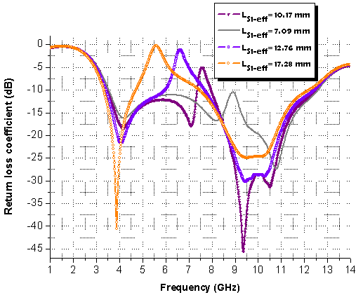 | Figure 11. Optimization of slot S1 by changing its effective length LS1-eff using the same radius (R1= 5 mm) |
Table 1. Half-guided wavelength corresponding to the effective length of the slot S1 for each Θ angle
 |
| |
|
3.2. Configuration C
In order to more improve S11 at 9 GHz, a second small circular half wavelength slot S2 of R2=3 mm radius and 1 mm width was inserted as in figure 12.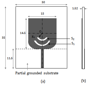 | Figure 12. Configuration C (unit: mm) |
The effective length of the second slot is  . As a result, the radiator with double slots S1 and S2 shows a large improvement in S11 compared to the antenna with only a single slot S1 as observed in figure 13.
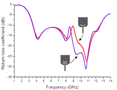 | Figure 13. Simulated return loss coefficient corresponding to the configurations B and C |
The simulated peak gain of the antenna, with the two embedded slots, is depicted by figure 14. The curve in figure suggests a considerable directivity compared to its electrical dimensions. In the band ranging from 2 GHz to 14 GHz, the minimum gain of 1.8dBi is observed at the lowest frequency 2 GHz and a maximum gain of 7.2dBi at 12 GHz. with a value 7.2dBi. The jitter behaviour presented in the figure might be attributed to the irregular currents around the slots. A slight reduction in gain is observed for frequencies higher than 13 GHz resulting in a drop in antenna efficiency at the higher end of the frequency range. 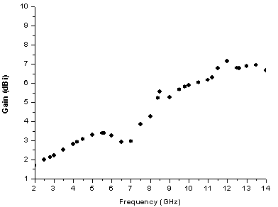 | Figure 14. Simulated peak gain of the printed antenna with two circular slots |
4. Conclusions
In this paper, bandwidth enhancement by non-uniform impedance matching and small circular embedded slots has been introduced. The bandwidth is ranging from 3.5 GHz to 12.5 GHz for S11 (dB) < -10dB. The measured radiation patterns of the prototype without slots are nearly omnidirectional in both E and H planes. Due to its compact size of 30 x 35 mm2 and its good impedance matching especially in the X band, this antenna is capable of satisfying some of the requirements of an airborne SAR, as well as for remote sensing applications.Further investigations are carried on to provide asystematic procedure allowing matching and band enhancement by means of appropriate profiles of transmissions structures.
References
| [1] | “First report and order in the matter of revision of Part 15 of the commission’s rules regarding ultra-widebandtransmission systems,” Federal Communications Commission, Washington, DC, ET-Docket 98-153, 2002. |
| [2] | Waynes S. T. Rowe and Rod B. Waterhouse, ‘‘Investigation Into the Performance of Proximity Coupled Stacked Patches,’’ IEEE Transaction on antenna and propagation, June 2006, pp 1693-1698. |
| [3] | Dan Sun and Lizhi You, A Broadband Impedance Matching Method for Proximity Coupled Microstrip Antenna, IEEE Transaction on antenna and propagation, April 2010, pp 1392-1397. |
| [4] | James R. Kelly, Peter S. Hall, Peter Gardner, Planar Band-Notched UWB Antenna, 3rd Conference Eucap’2009, March 2009, pp 1636-1639. |
| [5] | K. L. Wong, Compact and broadband microstrip antennas, Wiley, NY, 2002. |
| [6] | Chow-Yen-Desmond Sim, Wen-Tsan Chung, and Ching-Her Lee, ‘‘Compact Slot Antenna for UWBApplications,’’Antenna and Wireless Propagation letters, 2010, pp 62-66. |
| [7] | Aliakbar Dastranj and Habibollah Abiri, Bandwidth Enhancement of Printed E-Shaped Slot Antennas Fed by CPW and Microstrip Line,’’ IEEE Transaction on antenna and propagation, April 2010, pp 1402-1407. |
| [8] | C.-C. Lin and H.-R. Chuang, ‘‘A 3-12 GHZ UWB planar triangular monopole antenna with ridged ground-plane, ‘’ Progress In Electromagnetics Research, vol. 83, 2008, pp. 307–321. |
| [9] | Seok H. Choi, Jong K. Park, Sun K. Kim, and Jae Y. Park, A new ultra-wide band antenna for uwb application, Microwave and Optical Technologies Letters, March 2004, pp 399-401. |
| [10] | D. Chen and C. H. Cheng, ‘‘A novel compact ultra-wideband (UWB) wide slot antenna with holes,’’ Progress In Electromagnetics Research, vol. 94, 2009, pp. 343-349. |
| [11] | R. Fallahi, A. A. Kalteh, and M. G. Roozbahani, ‘‘A optical slot antenna with band-notched characteristics,’’ Progress In Electromagnetics Research, vol. 82, 2008, pp. 127–136. |
| [12] | G.-M. Zhang, J.-S. Hong, and B.-Z. Wang, ‘‘Two novel band-notched UWB slot antennas fed by microstrip line,’’Progress In Electromagnetics Research, vol. 78, 2008, pp. 209–218. |
| [13] | M. Ojaroudi, Sh. Yazdanifard, N. Ojaroudi, and R. A. Sadeghzadeh, “Band-Notched Small Square-Ring Antenna with a Pair of T-Shaped Strips Protruded Inside the square Ring for UWB Applications”, IEEE Antennas and propagation letters, vol. 10, Avril 2011, pp. 227-230. |
| [14] | Yvan Duroc, Tan-Phu Vuong, and Smail Tedjini, A Time/Frequency Model of Ultrawideband Antennas, IEEE Transaction on antenna and propagation, August 2007, pp 2342-2350. |
| [15] | Trang Dang Nguyen, Dong Hyun Lee, and Hyun Chang Park, ‘‘Design and analysis of compact printed triple band-notched UWB antenna,” IEEE Antennas and wireless propagation letters, vol. 10, Mai 2011, pp. 403-406. |
| [16] | J. Y. Sze and K. L. Wong, “Bandwidth enhancement of a microstripline-fed printed wide-slot antenna,” IEEE Trans. Antennas Propag., July 2011, pp. 1020-1024. |
 Abstract
 Reference
 Full-Text PDF
 Full-text HTML