International Journal of Electromagnetics and Applications

p-ISSN: 2168-5037    e-ISSN: 2168-5045

2012;  2(6): 140-144

doi: 10.5923/j.ijea.20120206.01

Hemispherical Dielectric Resonator Antennas over Non-Planar Surfaces for Direction Finding Systems

S. H. Zainud-Deen 1, Noha A. El-Shalaby 2, K. H. Awadalla 1

1Faculty of Electronic Engineering, Menoufia University, , Menoufia, Postcode, Egypt

2Faculty of Engineering, Kafrelsheikh University, Kafrelsheikh, Postcode, Egypt

Correspondence to: Noha A. El-Shalaby , Faculty of Engineering, Kafrelsheikh University, Kafrelsheikh, Postcode, Egypt.

Email:

Copyright © 2012 Scientific & Academic Publishing. All Rights Reserved.

Abstract

In this paper, hemispherical DRA array mounted on or embedded in a hollow circular cylindrical ground structure is used for direction finding systems. In the proposed array only one DRA element is active and the others are parasitic. The direction of the received signal will be determined by the relation between the received signal strengths at each element of the array.

Keywords: DRA, SPA, PE, FEM, FIT, PDE

Cite this paper: S. H. Zainud-Deen , Noha A. El-Shalaby , K. H. Awadalla , "Hemispherical Dielectric Resonator Antennas over Non-Planar Surfaces for Direction Finding Systems", International Journal of Electromagnetics and Applications, Vol. 2 No. 6, 2012, pp. 140-144. doi: 10.5923/j.ijea.20120206.01.

1. Introduction

Switched beam array can be used in a lot of communication applications such as base station tracking in mobile communication, wireless networking, motor vehicles, aircrafts, robots, radar, security systems, and detection of transmitter direction as needed in direction finding systems. In[1], a switched parasitic array (SPA) is considered by using parasitic elements (passive elements, PE) that can be shorted to ground by pin-diodes. The array is consisting of one fed element and several other parasitic elements. Switching between different identical patterns but pointing to different directions can be achieved using a coordinated shortening of the passive elements.
Beam steering that is affected by mechanical steering, require complex feeding network, high power to operate, and its angular resolution is related to the beamwidth of the antenna. That can be achieved in crossed loop arrays, a highly directional arrays and phased arrays. But controlled directional patterns with electronically steerable beam are more efficient and useful. The control of the position of the feed element in an array to change the direction of its beam reduces multipath fading and power consumption through increased antenna gain. Also, this method, similar to the phased array, offers promising solution, provides better performance and reduces cost of components and assembly[2-7]. The dielectric resonator antenna (DRA) has many advantages including wide bandwidth and high radiation efficiency that are necessary for thoseapplications[8-10]. The radiation characteristics of cylindrical DRA and
hemispherical DRA placed on or embedded in superquadric cylindrical, circular cylindrical and spherical ground planes are investigated in[11-15].
In this paper, the model for switched parasitic antenna array is considered. The hemispherical DRA array elements mounted on or embedded in circular cylindrical ground plane for direction finding system are investigated. The DRA antenna elements are equally distributed along the circumference of a finite hollow circular conducting cylinder. The beam can be switched by exchanging the position of the feed so that the direction of the maximum radiation in the horizontal plane is changed. The switching board was located inside the ground structure.
In this model, the radiation patterns of DRA elements are investigated to determine the angle of arrival of an incident wave using the relation between the received signal strength at each of the array elements. The finite element method (FEM)[16-17] is used to simulate the structure and the results are compared with that calculated by the finite integration technique (FIT)[18-19] for authentication.

2. Numerical Results

An Array of Hemispherical DRAs Mounted on A Circular Cylindrical Surface.
Figure.1 shows the hemispherical DRA element which is placed on a hollow circular cylindrical perfectly conducting ground plane. The hemispherical DRA ((Crystals (single, inorganic) Alkali halides, LiF)) with dielectric constant εr =8.9 is used. It has a radius a, of 1.88 cm (0.458λ). A coaxial probe with radius of 0.075 cm is used to excite the element. The probe is located off the center by df =1.288 cm with a height hP of 1.125 cm. The hemispherical DRA is designed to operate at 2.45 GHz (λ=12.245 cm). The radius of the circular cylinder is rg=7.5 cm (0.612λ), and the length, lg, is 10 cm.
Figure 1. The geometry of hemispherical DRA element mounted on a hollow circular cylindrical ground plane
The simulated reflection coefficient as a function of frequency and the radiation patterns for one element mounted on hollow circular cylindrical ground plane at f=2.45 GHz are illustrated in Fig.2. The simulated results are calculated using the FEM and compared with that calculated by FIT method. Good agreement is obtained. It is obvious that the main-lobe in the xy-plane radiation pattern goes beyond the ±90oin addition to a significant back lobe. This is because the diffraction effect due to the finite size of the cylindrical ground plane. The radiation pattern in the y-z plane is symmetric as expected with some high levels of the Eθ components in some directions. The backlobe is only about -6 dB relative to the maximum in the front as indicated in the x-z plane and the x-y plane plots. This indicates a significant backward radiation, which is expected as the radius of the conducting ground plane cylinder is only 0.612λ.
Figure.3 shows the switched-parasitic antenna array. It consists of four hemispherical DRA elements that are equally spaced and placed on a hollow circular cylindrical ground plane. The antenna array consists of one active element and three parasitic elements. The array is electronically switched sequentially to each of the four positions of the antennas and then detects the signal strengths v1, v2, v3 and v4 at each switch positions 0o, 90o, 180o, 270o, respectively. The radiation patterns in x-y plane are calculated for all four directions as shown in Fig.4. This is almost the same pattern of a single element but switched in the four directions. The mutual-effect of the elements on each other is negligible.
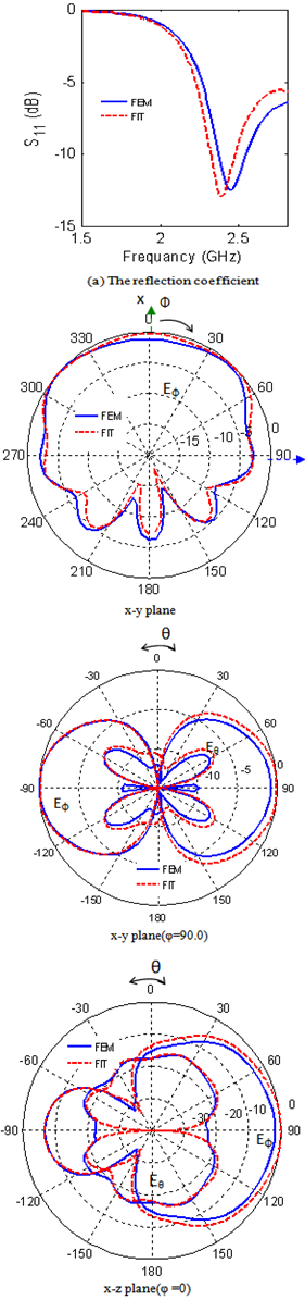
Figure. 2. The reflection coefficient and the radiation patterns in different planes at rg =75mm
Figure 3. The geometry of switched-parasitic DRA array mounted on a hollow circular cylindrical ground plane
Figure 4. The radiation patterns of four-element hemispherical DRA array mounted on a hollow circular cylindrical ground plane in x-y plane
An Array of Hemispherical DRAs Embedded in A Circular Cylindrical Surface.
For more economy and for getting rid of the elements protrusion because of using the DRA elements sticking out of the surface, a hemispherical DRA array with elements embedded in hollow circular cylindrical ground plane structure loaded with protecting dielectric superstrate is proposed as shown in Fig.5. The superstrate layer directly loads the hemispherical DRA. It has been selected to be RT/duroid 5880 and to have a relative permittivity εrs= 2.2, a thickness hc = 2.22 cm and rc =2.96 cm. For one element, the simulated reflection coefficient versus the frequency is shown in Fig.6, which indicates a reduction of the resonant frequency to become 2.4 GHz due to the loading effect of the superstrate combined with the effect of the cavity used for embedding the DRA element.
Figure 5. The geometry of switched-parasitic DRA array embedded in a hollow circular cylindrical ground plane
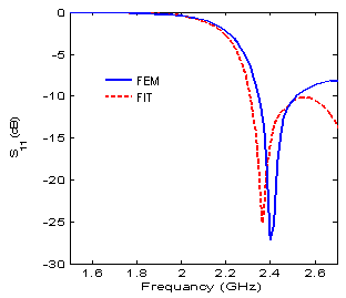
Figure 6. The reflection coefficient of one element hemispherical DRA embedded in a hollow circular cylindrical ground plane
Radiation patterns in x-y plane for four and five elements uniformly distributed around the hollow circular cylindrical ground plane are shown in Fig.6. For the case of four elements the switch positions produce the signal strengths (v1 or v2 or v3 or v4). By knowing the radiation pattern of the array, the exact determination of the angle of any signal source can be determined by simply ordering the two maximum signal strengths. The relations between the values v1, v2, v3 and v4 are shown in Fig.7. For example if v1 and v2 are the two largest signal strengths received in the scan and v1 >v2, then the source direction is located between 0o degree and 45o degrees. Then, using the branch in Fig.7 for v1/v2 or an equivalent formula, the angle of arrival can be determined in a more precise way.
Figure 6. The radiation patterns of hemispherical DRA array embedded in a hollow circular cylindrical ground plane in x-y plane
Figure 7. The output ratio between adjacent switches positions against the angle φ

3. Conclusions

Hemispherical DRA array mounted on or embedded in a hollow circular cylindrical ground structure is proposed for direction finding systems. The detected signal strengths v1, v2… at each switch positions, are used to get the exact determination of the angle of any incident signal, therefore it is quite suitable for the direction finding application. The proposed structures are simple and not costly.

References

[1]  T. Svantesson, M. Wennstrom, "High-resolution direction finding using a switched parasitic antenna," Proceedings of the 11th IEEE Signal Processing Workshop on Statistical Signal Processing, pp. 508 – 511, 6-8 August 2001.
[2]  M. R. Kamarudin, and P. S. Hall, "Switched beam antenna array with parasitic elements," Progress In Electromagnetics Research B, PIER-B, vol. 13, pp.187-201, 2009.
[3]  S. Preston, and D. V. Thiel, "Direction finding using a switched parasitic antenna array," IEEE Trans. Antennas Propag., vol. 13, pp. 1024-1027, June 1997.
[4]  R. Schlub, and D. V. Thiel, "Switched parasitic antenna on a finite ground plane with conductive sleeve," IEEE Trans. Antennas Propag., vol. 52, no. 5, pp. 1343 - 1347 , May 2004.
[5]  D. Uffler, E. Gschwendtner, and W. Wiesbeck, "Design and measurement of conformal antennas on cylindrical and spherical geometries," IEEE Trans. Antennas Propag., vol.2, no.2, pp. 1005-1010, June 1999.
[6]  S. L. Preston, D.V. Thiel, T.A. Smith, S.G. O'Keefe, and J.W. Lu, "Base-station tracking in mobile communications using a switched parasitic antenna Array," IEEE Trans. Antennas Propag., vol.46, no.6, pp. 841-844, June 1998.
[7]  S. H. Zainud-Deen, D.G. Moharram, K. H. Awadalla, and H. A. sharshar, "Circularly polarized switched parasitic quadrifilar helical arrays," 22th National Radio Science Conference (NRSC 2005), Cairo, Egypt, March, 2005.
[8]  G.P. Junker, A.A. Kishk, and A.W. Glisson, "Input impedance of dielectric resonator antenna excited by a coaxial probe," IEEE Trans. Antennas Propag., vol.42, no.7, pp. 960-966, July 1994.
[9]  K.M. Luk, and K.W. Leung, Dielectric Resonator Antenna, Research Studies Press, Hertfordshire, UK, 2003
[10]  A.A. Kishk, Y. Yin, and A.W. Glisson, "Conical dielectric resonator antennas for wideband applications," IEEE Trans. Antennas Propag., vol.50, no.4, pp. 469-474, April 2002.
[11]  S. H. Zainud-Deen, H. A. Malhat, and K. H. Awadalla," Dielectric resonator antenna mounted on a circular cylindrical ground plane," Progress In Electromagnetics Research B, PIER B, vol. 19, pp. 427-444, 2010.
[12]  S. H. Zainud-Deen, H. A. Malhat, and K. H. Awadalla," Cylindrical dielectric resonator antenna housed in a shallow cavity in a hollow circular cylindrical ground plane," 26th Applied Computational Electromagnetic Society (ACES) Conference, Tampere, Finland, April 2010
[13]  S. H. Zainud-Deen, Noha A. El-Shalaby, and K. H. Awadalla," Radiation Characteristics of Cylindrical Dielectric Resonator Antenna Mounted on Superquadric Cylindrical Body," Electrical and Electronic Engineering Journal, SAP, vol. 2, No. 3, pp.88-95, 2012.
[14]  S. H. Zainud-Deen, Noha A. El-Shalaby, and K. H. Awadalla ," Hemispherical DRA Antennas Mounted on or Embedded in Circular Cylindrical Surface for Producing Omnidirectional Radiation Pattern" International Journal of Communication, Network and System Sciences, vol.4, No.9, pp. 601-608, September 2011.
[15]  S. H. Zainud-Deen, Noha A. El-Shalaby, and K. H. Awadalla," Hemispherical Dielectric Resonator Antenna Mounted on or Embedded in Spherical Ground Plane With a Superstrate," Electrical and Electronic Engineering Journal, SAP, vol. 1, No. 1, pp.5-11, 2011.
[16]  P. Wriggers, Nonlinear finite element methods, Springer- Verlag, Berlin, Heidelberg, Germany, 2008.
[17]  J. Chessa, Programming the finite element method with Matlab, Annual Report, Northwestern University, October 2002.
[18]  I. Munteanu1 and T. Weiland, “RF & microwave simulation with the finite integration technique-from component to system design,” Scientific Computing in Electrical Engineering Mathematics in Industry, Part III, vol. 11, pp. 247-260, 2007.
[19]  U. Van Rienen, “Frequency domain analysis of waveguides and resonators with FIT on non-orthogonal triangular grids,” Progress in Electromagnetics Research (PIER), vol. 32, pp. 357-381, 2001.