Jean-Marie Floc H , Ahmad El Sayed Ahmad
IETR Laboratory, UMR CNRS 6164, 20 avenue des Buttes de Coesmes 35000 Rennes, France
Correspondence to: Ahmad El Sayed Ahmad , IETR Laboratory, UMR CNRS 6164, 20 avenue des Buttes de Coesmes 35000 Rennes, France.
| Email: |  |
Copyright © 2012 Scientific & Academic Publishing. All Rights Reserved.
Abstract
A Dual-band printed dipole antenna is proposed for 2.45 GHz Bluetooth (ISM) and wireless area network (WLAN) 5.8 GHz applications. The objective of the special design is to compensate the space attenuation difference between the frequency of 2.45 GHz and the frequency of 5.8 GHz. Like the space attenuation difference is about 3.5 dB, the studied antenna must to have 3 dB more gain at 5.8 GHz than at 2.45 GHz. The prototype is fabricated and measured, and the results are in good agreement with the simulated ones. The presented antenna achieves directional radiation in the two operating bands, and gets the performances that reflection coefficient better than -10 dB with sufficient bandwidth and gain 5-8 dB, making it suitable for the base station in wireless communications.
Keywords:
Printed Dipole Antenna, Gain Enhancement, Director And Reflector, Yagi Antenna
1. Introduction
Recently, wireless communication has grown exponentially worldwide. The Wireless local area network (WLAN) is considered as a cost effective and viable solution for high-speed data connectivity, enabling user mobility. The increasing demand in WLAN technology integrates both 2.45 GHz and 5.8 GHz frequency bands into one device, necessitating the requirement and development of a dual-band antenna. Various antenna designs such as those of microstrip line, coplanar waveguide, and PIFA dipole antennas have been presented in the literature. In[1], a novel miniature end-loaded planar open-sleeve dipole (ELPOSD) antenna was presented; it was demonstrated to have a large band-width and a short length. A printed dipole antenna with U-slotted arms was proposed in[2]. With the aid of an embedded U-shaped slot, it can generate a new resonant mode at 5.2 GHz. In[3, 4], printed dipole and monopole antennas with parasitic elements were presented. The experimental results show that parasitic strips can be coupled with dipole antennas in order to give rise to additional resonance modes. A broadband printed dipole antenna with a step shaped feed gap was proposed in[5]. The wide operating band is controlled by the different lengths of the radiation arms. Thus, it was demonstrated that a dipole antenna with parasitic elements has the ability to realise multi-band or broad-band operation. However, these antennas could not provide directional radiation. In this paper, we present a directional radiation in the two operating bands antenna. Throughout the last several years, many contributions have taken place in the design and optimization of Yagi-Uda antenna for specific applications[6-8]. For example, a small and slim printed Yagi-Uda antenna was designed for vehicle GPRS system application[6]. Also, a successful attempt to improve the gain of a single Yagi-Uda array using a periodic band gap (PBG) structure was proposed in[7], which is used for wireless computer networking. Additionally, a broad-band quasi-Yagi antenna achieving a measured 48% bandwidth is presented for radar systems and millimeter-wave imaging arrays in[8]. We have presented few year ago in[9] a multi-band frequency printed dipole antenna with operation at 2.45, 5.8 and 10 GHz.The paper is organized as follows: first, we present the design concept of the proposed printed dipole antenna with reflector which enables the Tx/Rx of a single-band frequency. In Section III, a parasitic element is embedded to enable the operation of dual-band. Finally, the printed dipole antenna with a higher gain of 3 dB at the frequency of 5.8 GHz is described. For the design and optimization of antennas, we use HFSS CAD software from ANSOFT. The antennas have been designed and successfully measured.
2. Single-Band Printed Dipole Antenna
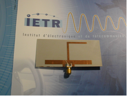
The single-band printed dipole antenna is composed of the dipole and reflector as shown in “Figure. 1”. The two arms of the dipole are printed on each side of a CuClad substrate of thickness 0.8 mm and permittivity of 2.17 (to overcome the complicated feeding technique). We use a microstrip line combined with a bifilar printed line. The length of these arms and the distance between them and reflector are around quarter-wavelength (λ0/4). λ0 is the wave-length in free space corresponding to resonant frequency around 2.45 GHz.The reflector has to be longer than the length of the two arms of the dipole in order to reflect the radiated power in the front direction (θ = 0°). In the case of a shorter reflector, the radiation is concentrated in back direction, it performs as a director (θ = 180°).The advantage of this structure is to increase the gain of the printed dipole and to decrease the backside radiation. The “Figure. 2” shows the realized printed dipole antenna with reflector. 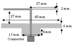 | Figure 1. Geometry of the printed dipole antenna with reflector |
 | Figure 2. Photo of the printed dipole antenna with reflector |
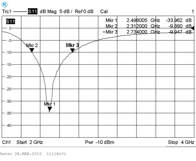
The simulated reflection coefficient evaluation is showed in “Figure. 3”. The printed dipole antenna is matched to -29 dB in simulation around the operating frequency. The measurements were achieved in the laboratory anechoic chamber and have been compared to simulation. The return loss of the tested antenna is presented in “Figure. 4”. The level of measured S11 is lower than -10 dB over the frequency bandwidth[2.3 GHz – 2.7 GHz].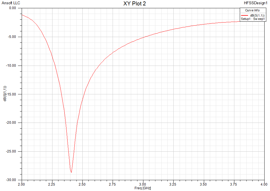 | Figure 3. Simulated reflection coefficient of the simple printed dipole |
 | Figure 4. Measured reflection coefficient of the simple printed dipole |
We present the radiation pattern in 3D at 2.45 GHz obtained in simulation and measurement (“Figure. 5” and “Figure. 6”). We note a good comparison between simulation and measurement. The measured gain in 0° and 180° direction are respectively 5 dB and – 8 dB at 2.45 GHz. The difference between the simulated realized gain and the measured realized gain is around 0.5 dB. The measurement accuracy of the anechoic chamber (± 0.5 dB) can be responsible for this variation.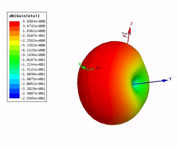 | Figure 5. Simulated 3D radiation pattern of the dipole antenna with reflector |
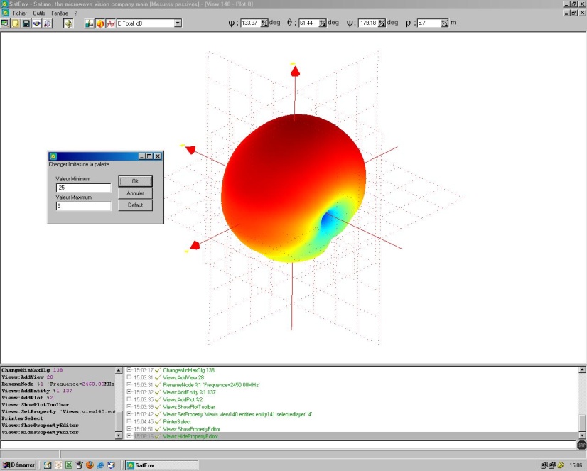 | Figure 6. Measured 3D radiation pattern of the dipole antenna with reflector |
3. Dual-Band Printed Dipole Antenna
The addition of one parasitic close to the simple printed dipole creates a second resonance frequency (“Figure. 7”). The resonant band is obtained through coupling between the dipole arms and the parasitic strip. This frequency is determined by the length of the parasitic around λ0/2. We have optimized the distance between dipole and reflector, the distance between dipole and parasitic strip. It is possible to see on the “Figure. 8” the two side of the antenna substrate.The distance between the dipole arms and the parasitic dipole is very short because the coupling between them is capacitive. This distance is optimized using EM Software in order to obtain the best performances. 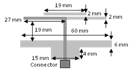 | Figure 7. Geometry of the dual-band printed dipole antenna with parasitic and reflector |
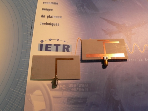 | Figure 8. Photo of the dual-band printed dipole antenna with parasitic and reflector |
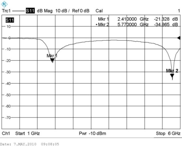
The simulated reflection coefficient of the dual-band printed dipole is presented on the “Figure. 9”. The simulated resonance frequencies are 2.45 GHz and 5.8 GHz, with return losses of -30 dB and -25 dB, respectively. The bandwidth is 14.3% and 6.4% in the lower and upper frequency bands respectively. The antenna is fabricated, and the measurement is performed (“Figure. 10”). We note a good similarity between measurement and simulation. The measured E-plane and H-plane radiation patterns at the lower and upper frequency bands are shown in “Figure. 11” and “Figure. 12”. We measure at 2.45 GHz a maximum gain equal to 5.2 dB for a simulated one of 5.6 dB. At 5.8 GHz, we measure a maximum gain equal to 1.8 dB. We note a small gain at higher frequency for dual-band antenna without director. It is because we don’t optimize this antenna in term of gain but only for reflection coefficient.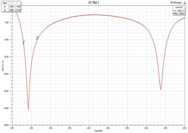 | Figure 9. Simulated reflection coefficient of the dual-band printed dipole antenna |
 | Figure 10. Measured reflection coefficient of the dual-band printed dipole antenna |
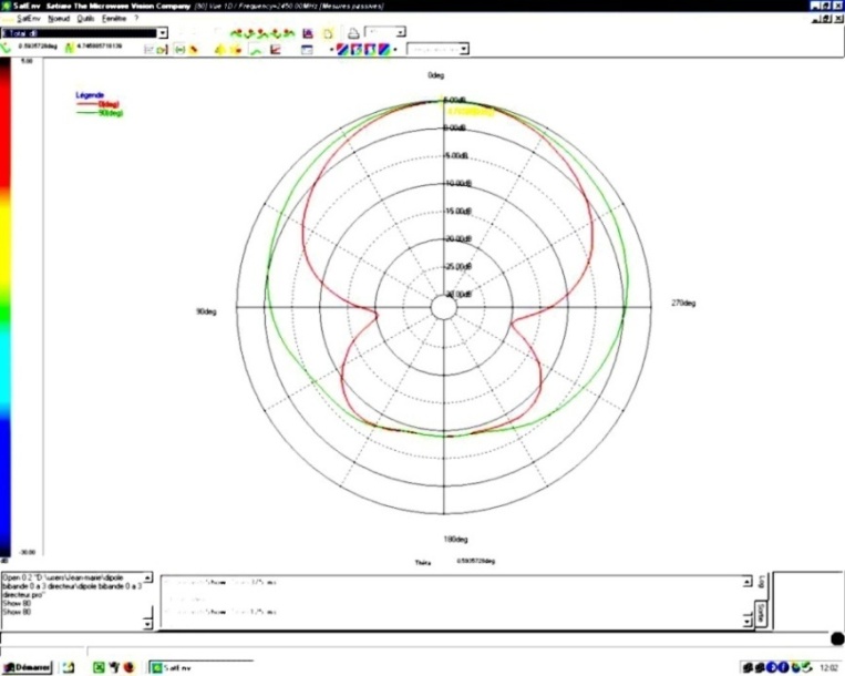 | Figure 11. Measured radiation pattern (red: E-plane, green: H-plan) of the dual-band printed dipole antenna at f = 2.45 GHz (Gain = 5.2 dB) |
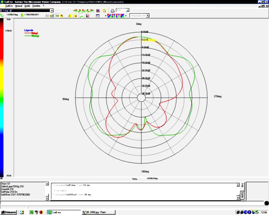 | Figure 12. Measured radiation pattern (red: E-plane, green: H-plan) of the dual-band printed dipole antenna at f = 5.8 GHz (Gain = 1.8 dB) |
4. Dual-Band Printed Dipole Antenna with Directors
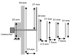 | Figure 13. Geometry of the proposed printed dipole antenna with 3 directors |
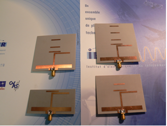 | Figure 14. Photo of the proposed printed dipole antenna with 0, 1, 2 and 3 directors |
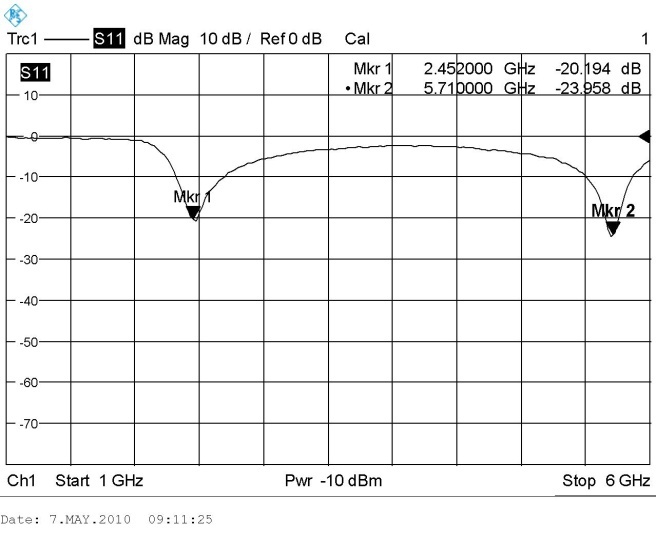
In order to increase the gain at higher frequency, we put directors near the parasitic dipole. The schematic of the proposed antenna is shown in “Figure. 13”. The distance between these directors is determined like it is done with Yagi antenna[10]. This distance is around λg/4 and can be determined in using classical Yagi antenna calculator. After that, the distance is optimized in using EM Software, in our case HFSS ANSOFT Software. We designed antennas with 1, 2 and 3 directors (“Figure. 14”). It is necessary to have 3 directors for having 3 dB more for the gain at the higher frequency 5.8 GHz versus 2.45 GHz.We present the simulated and measured reflection coefficient for the 3 director antenna on the “Figure. 15” and “Figure. 16”. The simulated and measured resonance frequencies are 2.45 GHz and 5.8 GHz, with return losses of -25 dB and -20 dB, respectively.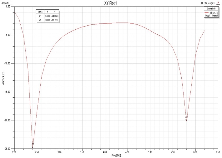 | Figure 15. Simulated reflection coefficient of the printed dipole antenna with 3 directors |
 | Figure 16. Measured reflection coefficient of the printed dipole antenna with 3 directors |
The measured E-plane radiation patterns at the lower and upper frequency bands are shown in “Figure. 17” and “Figure. 18”. We measure at 2.45 GHz a maximum gain equal to 5.3 dB for a simulated one of 5.6 dB. At 5.8 GHz, we measure a maximum gain equal to 8 dB. The “Figure. 19” present the variation of the gain for the dual-band printed dipole with 0, 1, 2 and 3 directors for the two bands 2.45 and 5.8 GHz.We note a stable gain for the lower band around 5 dB, a gain increase of 3 dB for one director and an increase of 5 dB for two directors and 6 dB for three directors. 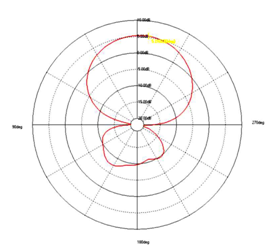 | Figure 17. Measured radiation pattern of the printed dipole antenna with 3 directors at f = 2.45 GHz (Gain = 5.3 dB) |
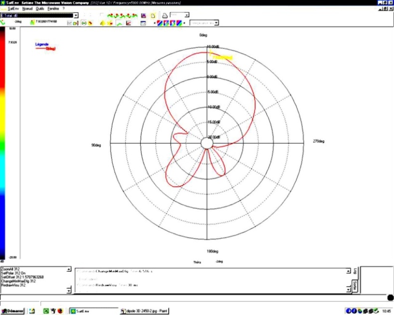 | Figure 18. Measured radiation pattern of the printed dipole antenna with 3 directors at f = 5.8 GHz (Gain = 8 dB) |
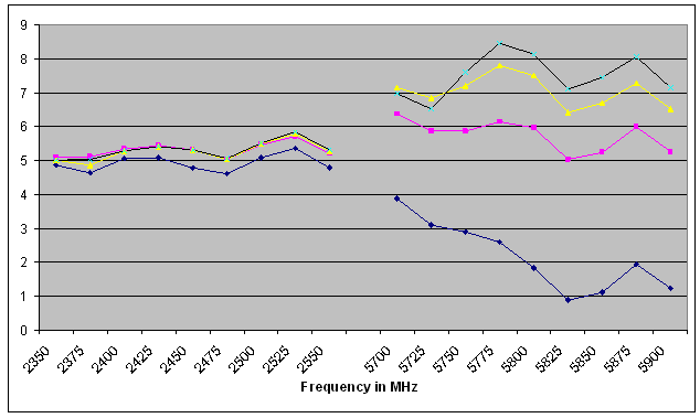 | Figure 19. Measured maximum gain in dB of the dual-band printed dipole with 0 (blue), 1(pink), 2(yellow) and 3(black) directors versus frequency |
5. Conclusions
A printed dipole antenna with a parasitic element for dual-band operation with compensation for the space attenuation at the higher frequency is proposed for WLAN applications. The first operating band is obtained from the dimensions of the rectangular dipole arms. By coupling the dipole arms and the arm parasitic element, it is shown that operation in two resonant modes was enabled. In order to increase the gain at higher frequency, we put 3 directors near the parasitic dipole. Then we obtain around 5 dB at 2.45 GHz and 8 dB at 5.8 GHz. The distances between these different elements are optimized by using CAD Software in order to obtain the best performances. The proposed antenna was successfully implemented and its performance was verified.Its advantages include compact size, dual-band performances, and directional radiation in the two operating bands were obtained. This technique can be proposed to different frequencies and different standards of communications systems.
References
| [1] | Spence, T.G., and Werner, D.H.: "A novel miniature broad-band/multiband antenna based on an end-loaded planar open-sleeve dipole", IEEE Trans. Antennas Propag., vol.54, no.12, pp. 3614–3620, 2006. |
| [2] | Su, C.M., Chen, H.T., and Wong, K.L.: "Printed dual-band dipole antenna with U-slotted for 2.4/5.2 GHz WLAN oper-ation", Electron.Lett., vol.38, no.22, pp. 1308–1309, 2002. |
| [3] | Chang, K., Kim, H., and Yoon, Y.J.: "A triple-band printed dipole antenna using parasitic elements", Microw. Opt. Technol. Lett., vol.47, no.3, pp. 221–223, 2005. |
| [4] | Coulibaly, Y., Denidni, T.A., and Talbi, L.: "Broadband coplanar waveguide-fed printed monopole antenna with strip-sleeves", Microw. Opt. Technol. Lett., vol.48, no.2, pp. 209–212, 2006. |
| [5] | Chi, Y.W.,Wong, K.L., and Su, S.W.: "Broadband printed dipole antenna with a step-shaped feed gap for DTV signal reception", IEEE Trans. Antennas Propag., vol.55, no.11, pp. 3353–3356, 2007. |
| [6] | Dong-Zo Kim, Seo-Young Park and Won-Seok Jeong,: "A small and slim printed Yagi antenna for mobile applications" , Microwave Conference, 2008. APMC 2008. |
| [7] | Olivier Kramer, Tarek Djerafi, and Ke Wu,: "Vertically Multilayer Stacked Yagi Antenna with Single and Dual Po-larizations", IEEE Trans. Antennas Propag., vol.58, no.4, pp.1022- 1030, 2010. |
| [8] | Noriaki Kaneda, W. R. Deal, Yongxi Qian, Rod Waterhouse, and Tatsuo Hoh: "A Broad-Band Planar Quasi-Yagi Antenna", IEEE Trans. Antennas Propag, vol. 50, no. 8, 2002. |
| [9] | J.M. Floc'h, H. Rmili,: "Design of multiprinted dipole antennas using parasitic elements", Microw. Opt. Technol. Lett., vol.48, no.8, pp. 1639–1645, 2006. |
| [10] | J.M. Floc'h, J.M. Denoual, K. Sallem,: "Design of printed dipole with reflector and multi directors", LAPC 2009 Loughborough, UK. |


 Abstract
 Reference
 Full-Text PDF
 Full-Text HTML