Archana Nanoty 1, A. R. Chudasama 2
1Electrical Engg. Department, Sigma Institute of Engineering, Bakrol, Ajwa-Nimeta Road, Vadodara, Gujarat, 390019, India
2Department of Electrical & Electronics, Faculty of Technology, The M. S. University, Vadodara, Gujarat, 390001, India
Correspondence to: Archana Nanoty , Electrical Engg. Department, Sigma Institute of Engineering, Bakrol, Ajwa-Nimeta Road, Vadodara, Gujarat, 390019, India.
| Email: |  |
Copyright © 2012 Scientific & Academic Publishing. All Rights Reserved.
Abstract
Amongst many types of electrical motors, induction motors still enjoy the same popularity as they did a century ago. Several factors which include robustness, low cost and low maintenance have made them popular for industrial applications when compared to dc and other ac motors. Another aspect in induction motor drives which has been researched recently is the use of multiphase induction motors where the number of stator phases is more than three. Here, a multi-phase system is a system with more than three stator phases. For machine drive applications, multiphase induction motor could potentially meet the demand for high power electric drive systems which are both rugged and energy efficient. High phase number drives possess several advantages over conventional three phase drives such as reducing the amplitude and increasing the frequency of torque pulsation, reducing rotor harmonic currents, reducing the current per phase without increasing the voltage per phase, lowering the dc link current harmonics, higher reliability and increased power. Multiphase induction motors have found many applications such as electric/hybrid vehicles, aerospace applications, ship propulsion etc.
Keywords:
Six Phase Induction Motor, Variable Frequency, Vector Control
1. Introduction
Three-phase induction machines are today a standard for industrial electrical drives. Cost, reliability, robustness and maintenance free operation are among the reasons these machines are replacing dc drive systems. The development of power electronics and signal processing systems has eliminated one of the greatest disadvantages of such ac systems, which is the issue of control. With modern techniques of field oriented vector control, the task of variable speed control of induction machines is no longer a disadvantage, the need to increase system performance, particularly when facing limits on the power ratings of power supplies and semiconductors, motivates the use of increased phase number, and encourages new PWM techniques, new machine design criteria and the use of harmonic current and flux components.In a multiphase induction motor, more than three phase windings are housed in same stator and the current per phase in the motor is thereby reduced. In the most common of such structures two sets of three phase windings are spatially phase shifted by 300 electrical (Figure 1). In such motors each set of three phase stator winding is excited by a three Phase inverter, therefore total power rating of the system is theoretically doubled. It is also believed that drive system with multiphase induction motors will improve the system reliability. Ward and Harner for the first time in 1969 have presented the preliminary investigation of an inverter fed five phase induction motor and suggested that the amplitude of torque pulsation can be reduced by increasing the number of stator phases.[4]. Very few examples of design of multiphase induction motors can be found in the literature. Hamid Toliyat[17] has reported the test results on five phase motors. The reason given for using five phases was to reduce the current such that it would match the ratings of available thyristors, for inverter source. However, the third harmonic current was found to be excessive when it was supplied by inverter. Motors with many phases have been proposed for high degree of reliability. These few attempts to develop multiphase induction motors show that they have some advantages over conventional three phase induction motors.Recent surveys of the state-of-the art in this area[1, 4] indicate an ever increasing interest in multiphase machines within the scientific community world-wide. After extensive literature surveys it is observed that very little research efforts are applied in the direction of practical design, development and control of multiphase induction motors. So the goal of this research is to design and develop a six phase prototype induction motor, this novel design should be free from third harmonic current injection for torque improvement. Aim of this research is also to control the speed of developed prototype six phase induction motor with arbitrary phase displacement using vector control technique. This paper focuses on design, development and testing of six phase prototype induction motor and then the control of same motor is discussed.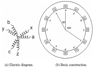 | Figure 1. Basics of Six Phase Induction Motor |
2. Multiphase Induction Motors
In traditional electric machine applications a three-phase stator winding is selected, since the three-phase supply is readily available. However, when an AC machine is supplied from an inverter, the need for a predefined number of phases on stator, such as three, disappears and other phase numbers can be chosen.The early interest in multiphase machines was caused by the possibility of reducing the torque ripple in inverter fed drives, when compared to the three-phase case. Another advantage of a multiphase motor drive over a three-phase motor drive is an improved reliability due to fault tolerance features, this being one of the main reasons behind the application of six-phase (double-star) and nine-phase (triple-star) induction motor drives in locomotives[48].
3. Design & Development
To begin with, an m-phase symmetrical induction machine, such that the spatial displacement between any two consecutive stator phases equals α = 2π/m, is considered. Stator winding is treated as m–phase and it is assumed that the windings are sinusoidally distributed, so that all higher spatial harmonics of the magneto-motive force can be neglected. The phase number m can be either odd or even. When the number of phases is six, i.e. m = 6, there are two, three phase windings. The two, three phase windings are displaced by 600 in symmetrical design but there is a problem of magnetic circulating currents. So asymmetrical design is implemented in which two, three phase windings are displaced by 300, which eliminates (6n  1) order harmonics, where n = 1,3,5……….[1].A six phase machine can be easily constructed by splitting the 600 phase belt into two portions each spanning 300.The winding distribution factor increases from 0.965 for three phase to 1.0 for six phase for split phase belt connection.[4] Stator design depends upon number of stator slots. General expression for number of stator slots is given by,
 | (1) |
WhereSs = No. of Stator Slotsm = No. of machine phasesp = No. of machine polesK = 0,1,2…..For Symmetrical ac winding: K = 0,2,4…..For Asymmetrical ac winding: K = 1,3,5….In this case no. of poles = 4, so putting the values of m, p, K in equation[3.1] we get,  | (2) |
Thus it is a 4-pole machine with 36 stator slots. In order to keep the leakage distribution balanced, the phases are displaced among the two stator layers. The six-phases are constructed such that one three-phase group is displaced from the other one by 30 electrical degrees.Thus, it is an asymmetrical six phase machine where; | (3) |
 | (4) |
 | (5) |
Hence, the 30 electrical degrees displacement corresponds to 15°/10° = 1.5 slots.It is not possible to implement such a configuration and an approximation has to be used. This is done as shown below:One of the three-phase groups has the same structure of the baseline machine with half of the circuits and winding distributed in 3 slots per pole per phase (qA = 3)The second group is distributed into 4 slots per pole per phase (qX = 4) but keeping the same number of conductors per pole per phase. Initially the same dimensions as per 3 phase, 3 HP, induction motor have been used. And stator is divided into two parts and winding is carried out as discussed above.Prototype six phase induction motor is developed in such a way that, first three phase set say, “ABC” has two pole pitches viz. 9 for outer layer and 7 for inner layer. While the second three phase set say “XYZ” has two pole pitches viz.8 for outer layer and 6 for inner layer. The number of poles is kept same for both the windings. Also wire gauge and number of turns are same for both the windings. The neutrals of two three phase sets are kept open. The motor is star connected.
3.1. Calculations
To design main dimensions of 3 HP (2.238 KW), 200 Volts, 6phase, 4 pole induction motor (assuming efficiency η= 85%, power factor cosΦ = 0.8 lagging | (6) |
 | (7) |
 | (8) |
 | (9) |
Kw = Window space factor for 6 phase = 1Assuming Specific magnetic loadings Bav = 0.65 wb/m2 ,Specific electric loading, 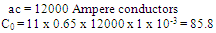 | (10) |
Putting the value of C0 from (10) in (8) | (11) |
Taking overall good design condition, | (12) |
 | (13) |
 | (14) |
Similarly turns per phase, | (15) |
 | (16) |
Stator slots Ss =36, no. of phases m =6Thus Total conductors = 3744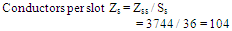 | (17) |
The standard dimension stamping available at the manufacturing unit near to the calculated value are selected. Standard Stator bore diameter available is 125 mm, nearest to the calculated value 124 mm. And stack length as per standard is selected as 100mm nearest to 102 mm. The final dimensions and specifications of motor are as shown below:-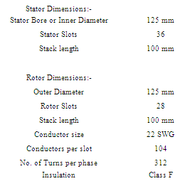
 | Actual Photograph of designed, developed Six phase, 3 HP Induction Motor |
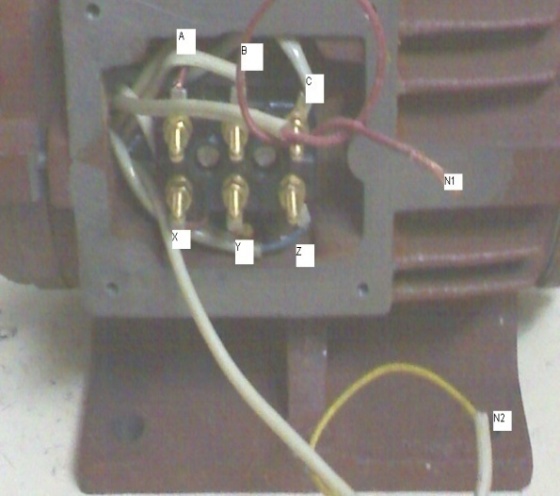
Above photograph shows the two three phase sets ABC and XYZ with neutrals N1 and N2.
4. Testing
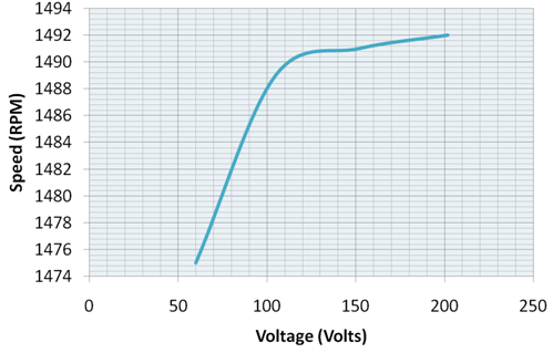
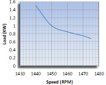
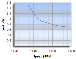
There is no standard separately for six phase induction motor. Thus the routine tests which are carried out for three phase motor, the same tests are carried out on prototype. It is considered like two, three phase induction motors sharing the same magnetic circuit and same shaft but electrically separated. Thus routine tests as per IS standards are carried out, by taking two three phase sets (say ABC and XYZ ) one by one.a. HV Test:- A 2 KV voltage is given to the terminal box between phase to phase and phase to earth for one minute and there should be no sparking. If there is sparking, there may be inter turn fault. Prototype six phase induction motor is tested like, two three phase stators sharing same shaft and same magnetic circuit and electrically separate. Prototype six phase induction motor satisfies this test, i.e. there is no sparking.b. Insulation Resistance (IR) Test: - Insulation resistance as per IS-325, should be 1 Mega Ohm. Prototype six phase induction motor has insulation resistance 1MΩ.c. No load Test: - Motor is run at rated voltage at no load and rated speed. No load test results with waveform are shown below. Figure 2 and 3shows the No Load Characteristics when ABC and XYZ energized respectively.d. Blocked rotor test:- Full load current is passed when the rotor is locked. Test results are shown belowVsc = 64 V, Isc = 9.44 AWsc = 0.56 KwSpeed N = 1460 rpme. Temperature rise Test:- Motor is run continuously for about a day and its temperature rise is noted, if it is getting overheated, winding and insulation is to be checked.f. Load test:- Motor is loaded gradually at 50%, 75%, and 100%. Test waveforms are shown below. Figure 4.3 and 4.4 shows the speed-load characteristics when ABC and XYZ loaded one by one respectively.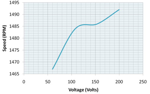 | Figure 2. No Load Characteristics when ABC terminals energized |
 | Figure 3. No Load Characteristics when XYZ terminals energized |
 | Figure 4. Speed- Load Characteristics when ABC terminals energized |
 | Figure 5. Speed- Load Characteristics when XYZ terminals energized |
5. Speed Control
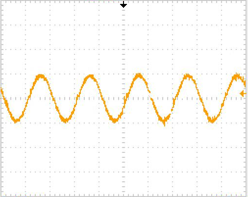
The motor is also tested with single three phase Voltage source inverter. This is done to check the suitability of the developed six phase motor for variable frequency operation. The three phase and six phase current waveforms are obtained and compared. The six phase current is double than that of three phase current. (From figure 6 and 7)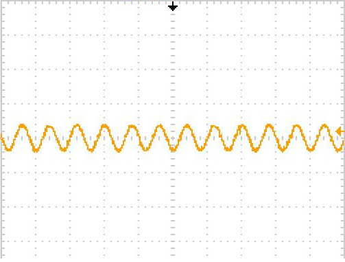 | Figure 6. Three phase current when only one three phase set energized through inverter |
 | Figure 7. Six phase current when six phases energized through inverter |
To carry out control of prototype six phase induction motor, the two three phase SVPWM inverters with synch (Synchronization card for synchronization between two inverters) is essential. The synch is an essential requirement when six phase induction motor is fed from two numbers of three phase inverters. It is decided to carry out innovative control of prototype six phase induction motor. The novel control is possible if the six phase prototype motor runs like two three phase induction motors having common shaft.As shown in figure 8 each set of the three phase stator windings is fed by a six pulse voltage source inverter (VSI). These VSIs may operate according to trigger signals produced by the controller and generate voltages phase shifted by 600/n. The controller can be a digital signal processor (DSP).Figure 8 presents the basic block diagram of the six phase induction motor fed from two, three phase drives. The frequency converter mechanically consists of two units, the Power Unit and the Control Unit.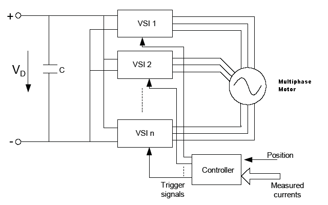 | Figure 8. Generalised Block Diagram of Multiphase Induction motor supplied from n number of inverters |
The three phase drive consists of three-phase AC-choke at the mains end together with the DC-link capacitor form an LC-filter, which, again, together with the diode bridge produce the DC-voltage supply to the IGBT Inverter Bridge block. The AC-choke also functions as a filter against High Frequency disturbances from the mains as well as against those caused by the frequency converter to the mains. It, in addition, enhances the waveform of the input current to the frequency converter. The entire power drawn by the frequency converter from the mains is active power.The IGBT Inverter Bridge produces a symmetrical, 3-phase PWM-modulated AC-voltage to the motor. The Motor and Application Control Block is based on microprocessor software. The microprocessor controls the motor on the basis of information it receives through measurements, parameter settings, control I/O and control keypad. The motor and application control block controls the motor control ASIC which, in turn, calculates the IGBT positions. Gate drivers amplify these signals for driving the IGBT inverter bridge.The control keypad constitutes a link between the user and the frequency converter. The control keypad is used for parameter setting, reading status data and giving control commands. It is detachable and can be operated externally and connected via a cable to the frequency converter. Instead of the control keypad, also a PC can be used to control the frequency converter if connected through a similar cable. Frequency converter can be equipped with a control I/O board which is either isolated (OPT-A8) or not isolated (OPT-A1) from the ground.Since Encoder and related circuitry required for high Power applications sensor control is costlier, sensor-less control is developed and implemented for controlling prototype induction motor. For sensor-less control, the motor control algorithm and Space vector Pulse width Modulation (SVPWM) for inverter are implemented. The mathematical model of the motor and control algorithm is fed into the Field Programmable Gate Array (FPGA), through Software. Matlab program is also loaded into FPGA.
5.1. Actual Control
Prototype six phase induction motor control is done as explained below:3HP, 200V, 50 Hz four pole 36 stator slots, star connected, six phase , squirrel cage induction prototype motor is supplied from two PC based separate Drives as per the rating of prototype motor, i.e. 3 HP, 200 volts, 4 pole, star connected six phase induction motor. This is done at Ac drives industry at Chennai. The drives which were used in controlling two, three three phase induction motors simultaneously same drives were selected as per prototype six phase induction motor. The motor speed is controlled like two, three phase induction motors connected to the same shaft and sharing the same magnetic circuit but electrically separated.The two inverters are synchronized properly with specially designed OPT-D2 card (Sync). The two inverters run in master-slave mode, i.e. one inverter acts as a Master and other as a slave or follower. Synchronization plays very important role in this control. If there is no proper synchronization then the motor cannot run. (figure 9)“NXP00002V178.VCN” software is used for two similar rating NXP drives (Drive having rectifier, SVPWM Inverter with FPGA). The motor speed control is carried out in two modes:1. Volts per hertz (v/f) , Scalar control (Frequency control Mode)2. Sensor less vector control. (Speed control Mode)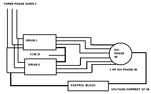 | Figure 9. Block diagram of Multiphase Induction motor fed by two three phase drives with control block |
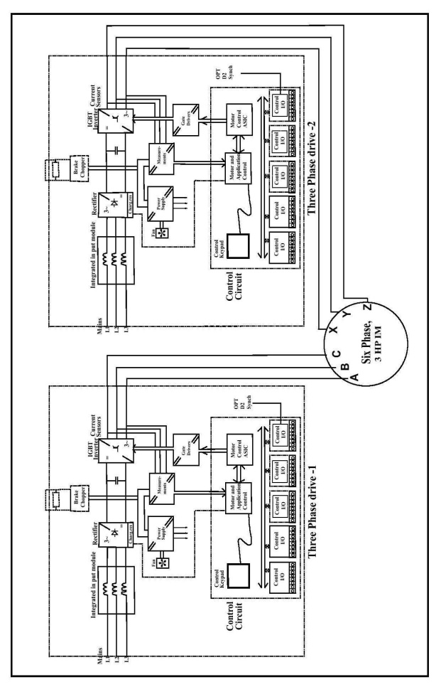 | Figure 10. Internal circuit of, two three phase drives used to feed two three phase sets of six phase Induction Motor |
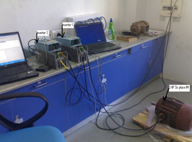 | Photograph of Actual Control of Six phase 3 HP prototype induction motor carried out at Chennai based Industry |
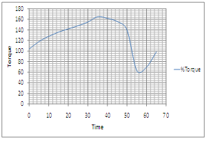
 | Figure 11. Torque of six phase IM for V/f control |
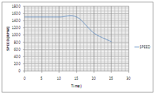
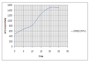 | Figure 12. Speed of six phase IM for V/f control |
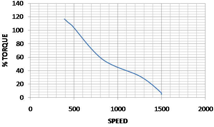 | Figure 13. Speed Torque curve for V/f control |
 | Figure 14. Torque of Six phase IM for vector control |
 | Figure 15. Speed of six phase IM for vector control |
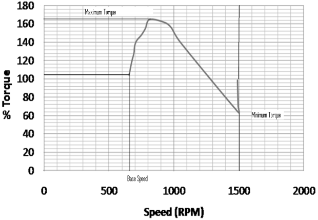 | Figure 16. Speed-torque curve for vector control of six phase IM |
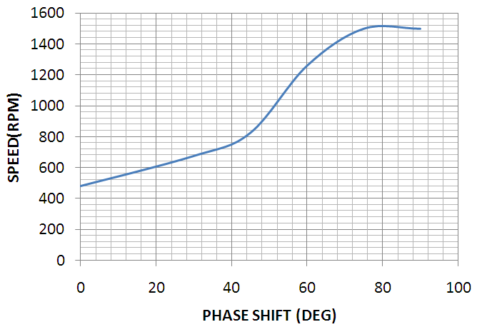 | Figure 17. Speed Vs phase shift for scalar control of prototype six phase IM |
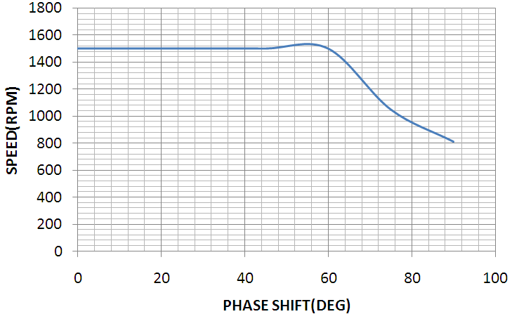 | Figure 18. Speed Vs phase shift for vector control of prototype six phase IM |
6. Discussion
Figures 11 to 13 show the torque, speed and Torque-speed characteristics of Six phase IM for v/f control. Figures 14 to 16 shows the torque, speed and Torque-speed characteristics of six phase IM. While phase shift versus speed for scalar and vector control respectively are shown in figures 17 and 18.The speed-Torque curve for Sensor-less vector control is superior to V/f i.e. scalar control. Smooth and fine control is obtained in sensor-less vector control as compared to scalar control. (Figures 13 and 16)The prototype six phase induction motor is controlled when fed from two, properly synchronized three phase inverters.
7. Conclusions
1. There is no criterion of maintaining 30 degrees phase shift, i.e. arbitrary phase shift. All control schemes developed till date were for 30 degree phase shift only.[4]-[5] (Figure 17 and 18)2. No third harmonic current injection or current sensor required for torque improvement: In this novel prototype six phase induction motor, the torque is found to be 1.6 times that of three phase induction motor torque. This is higher than 1.4 times as described in references[2],[1],[3]. This is achieved without third harmonic current injection for torque improvement and control with arbitrary phase displacement. The other features of a developed prototype six-phase induction motor are summarized as: 1. Improved reliability, i.e. if one inverter fails, the motor continues to run (though at reduced rating) thus continuity of operation is maintained, this is because the two neutrals are kept open.2. As losses are reduced, efficiency is improved as there are no circulating currents because of harmonic reduction due to 30 deg phase shift.3. By using 30 degrees phase displacement, for the same air gap flux, the inverter dc bus voltage is reduced by approximately a half (Because of 30 degrees displacement, voltage relations are like star-delta). 4. Also control is economical as sensor less vector control is implemented.Motor design is incomplete unless its speed is controlled. Thus the novel six phase induction motor development proved to be successful.
8. Limitations of the Design and Development
1. For higher rating, the size of the motor and hence inverter size becomes very large, which may increase the overall cost.2. Although sensor-less vector control is economical, the parameter variation problem particularly near zero speed imposes a challenge in the accuracy of speed estimation.(as seen from figure In Sensor less control there is no feedback so no error correction, Speed is estimated from the readings of output voltage and current.
9. Future Scope
1. Six phase motor can be designed with two stator windings with different number of poles so that two different speeds can be obtained as per number of poles.2. Multi motor operation, i.e. two or more multiphase motors can be supplied from single six phase inverter to get more torque wherever required, e.g. Electric Ship Propulsion.3. Same design can be extended in multiples of three, i.e. 9 phase, 12 phase, 15 phase motor as per the requirement of torque.
ACKNOWLEDGEMENTS
The authors are indebted to Dr. K.K. Thakkar, Director, Jyoti Ltd. for his invaluable support and financial assistance. Authors are also grateful to Mr. S. Salvi, Managing director, Vacon-India Ltd. Chennai for providing facilities to carry out control.
References
| [1] | Emil Levi, “Recent Developments in High Performance Variable-Speed Multiphase Induction Motor Drives” Sixth International Symposium Nikola Tesla, Belgrade, Serbia. 18th – 20th October, 2006. |
| [2] | K. Gopalkumar, Mahopatra, “A novel scheme for six phase induction motor with open end windings.” 28th Annual Conference of IEEE Industrial Electronics Society, Spain. 5th - 8th November, 2002. |
| [3] | Bojoi I. R.; Tenconi A. ; Griva G. ; Profumo F., “Vector Control of Dual-Three Phase Induction Motor Drives Using Two Current Sensors”, IEEE Industry Application Society Conference (Hong Kong (China)) pp.1805-1812 ISBN:0780392094, 2nd -6th October, 2005. |
| [4] | G. K. Singh, “Multiphase Induction Machine drive research”, Elsevier Journal, Electric Power System Research, Vol. 61, pp. 139-147, 2002. |
| [5] | Martin Jones, Slobodan N. Vukosavic, Emil Levi, Atif Iqbal, “A Six Phase Series Connected two Motor Drive with decoupled Dynamic Control”, IEEE Transactions on Industry Applications, Vol. 41, No. 4, July / August 2005. |
| [6] | A course in Electrical Machine Design- A. K. Sawhney, Dhanpat Rai & Co.(P) Ltd. New Delhi, 5th Edition - Reprint 2005. |
| [7] | Modern Power Electronics and AC Drives by Bimal K. Bose, Prentice Hall, USA. ISBN 0-13-016743-6, Printed in 2002. |
| [8] | Electric Motor drives- Modeling, Analysis and control By R. Krishnan, Prentice Hall of India Private Limited, New Delhi, India, ISBN-81-203-2168-5, Printed in 2002. |
| [9] | Fundamentals of Electrical Drives by G.K.Dubey, Narosa Publishing House, New Delhi, Second Edition 2001, Reprint 2002. |
| [10] | G. R. Arab Markadeh, J. Soltani, N. R. Abjadi, M. Hajian, “Sensor less Control of a Six-Phase Induction Motors Drive Using FOC in Stator Flux Reference Frame” World Academy of Science, Engineering and Technology (WASET), Issue 58, pp 890 – 896. October, 2009 |
| [11] | Dejan D. Reljic, Darko B. Ostojic, Veran V. Vasic, “Simple Speed Sensorless Control of Induction Motor Drive”, Sixth International Symposium Nikola Tesla, Belgrade, Serbia, 18th – 20th, October, 2006. |
| [12] | Mrs. Archana Nanoty, Dr. A.R. Chudasama “Multiphase Induction Motor, Modeling and Control”, International Journal IJ-ETA-ETS, Amoghsiddhi Education Society. January-June 2009 Issue. ISSN: 0975 – 6736. |
| [13] | Mrs. Archana Nanoty, Dr. A.R. Chudasama, “Application of Multiphase Induction Motor in Ship Propulsion”. Work Boat Ship Propulsion Seminar, Abu-Dabhi, UAE, 5th -7th October 2009. Paper was presented in seminar and then same was published In “Sea trade-Journal”, November 2009. |
| [14] | “Design of Multiphase Induction Motor for Ship Propulsion” IEEE Conference Electrical Ship Propulsion Technologies Symposium, (ESTS 2011) Alexandria, Virginia, USA, April 2011. Paper Put On IEEE-Explore. |
| [15] | “Comparison Of Three Phase Induction Motor With Six Phase Induction Motor Using Matlab Simulation”, International Journal Of Research in Electrical Engineering, ISSN: 0975 – 6736| Nov 09 To Oct 10 | Volume 1. |
| [16] | J. Prieto, F. Barrero, S. Toral, M. R. Arahal and M. J. Duran, “ FPGA Implementation of a Multiphase Space Vector Modulation for Asymmetrical Dual Three-phase AC Machines. International Conference on renewable Energies and Power Quality (ICRPQ’09), Valencia, Spain, 15th- 17th April 2009. |
| [17] | Shady M. Gadoue Ayman S. Abdel-Khalik, “Speed Estimation performance for Multiphase Induction Machines under Fault Conditions”, Proceedings of the 14th International Middle East Power Systems Conference (MEPCON’10), Cairo University, Egypt, Paper ID 218, pp. 515-520, 19-21, December, 2010 |
| [18] | DSP based Electromechanical motion control by Hamid A. Toliyat and Steven G. Campbell, (Chemical Rubber Company) CRC Press, Taylor and Francis Group. ISBN:9780849319181, Printed in 2003. |
 Abstract
 Reference
 Full-Text PDF
 Full-Text HTML