S. Gharehbaghian Azar 1, A. Alavi Gharahbagh 2, J. Nourinia 3, Ch. Ghobadi 3
1IT Department, Iran telecom, CO West Azarbaijan, Artesh st. Urmia, Iran
2Department of electrical and computer engineering, Islamic Azad University, Shahrood branch, Shahrood, Iran, Zip
3Electrical Engineering Department, University of Urmia, Doctor beheshti st, Urmia, Iran
Correspondence to: A. Alavi Gharahbagh , Department of electrical and computer engineering, Islamic Azad University, Shahrood branch, Shahrood, Iran, Zip.
| Email: |  |
Copyright © 2012 Scientific & Academic Publishing. All Rights Reserved.
Abstract
A novel design of a Plate ZAGI Antenna with HIS reflector is proposed, analyzed, simulated and implemented in this paper. In this Antenna instead of normal reflectors we use a high impedance surface reflector. It is made of continuous metal that conducts dc current and eliminates ac current with a certain bandwidth. This new surface omits surface waves and so, image currents are not phase reversed. Simulation and experimental results show a very considerable gain increasing in proposed antenna against usual antenna.
Keywords:
Zagi Antenna, High Impedance Reflector, Surface Waves
1. Introduction
Surface waves appear in many antennas. On a finite ground plane, surface waves propagate until they reach an edge or corner, where they can radiate into free space[1]. The result is a kind of multi path interference or “speckle,” which can be seen as ripples in the radiation pattern. Moreover, if multiple antennas share the same ground plane, surface currents can cause unwanted mutual coupling. By incorporating a high impedance surface (HIS) on a conducting surface it is possible to alter its radio frequency electromagnetic properties and suppress surface waves[2].David Jefferies and Dan Handelsman[3], reported the concept of the Zagi, an antenna made from slow wave structures which has controlled coupling between the elements and which can be made significantly smaller than a standard rod Yagi-Uda antenna. They suggested that the slow wave elements could be made from zigzagged wires Or a serrated plate elements that these elements are easy to design, build, model and have useful performance. This class of antenna exhibits smaller size, better Control of coupling and f/b ratio in compare with another type.In light of these applications, we present a novel antenna that used HIS (High impedance surface) as a reflector instead of general reflectors and our simulation result show that some parameters such as gain, f/b, etc of plate ZAGI antenna are significantly improved. The validity of our simulation result is completely demonstrated by experimental result.
2. Antenna Structure and its Operational Mechanism
2.1. High Impedance Surface (HIS)
A highly conductive flat surface has a very low surface impedance, which would result a reflection coefficient R = -1 for incident wave on this surface. However, If the surface is designed to have very high surface impedance, the reflection coefficient R is equal to 1, which its property is similar to an "artificial magnetic conductor"[4, 5]. For a surface with R = 1, for better radiation performance the horizontal wire antennas should be laid near the surface. In this situation the image current will be in phase with the antenna current, Fig. 1 (middle panel).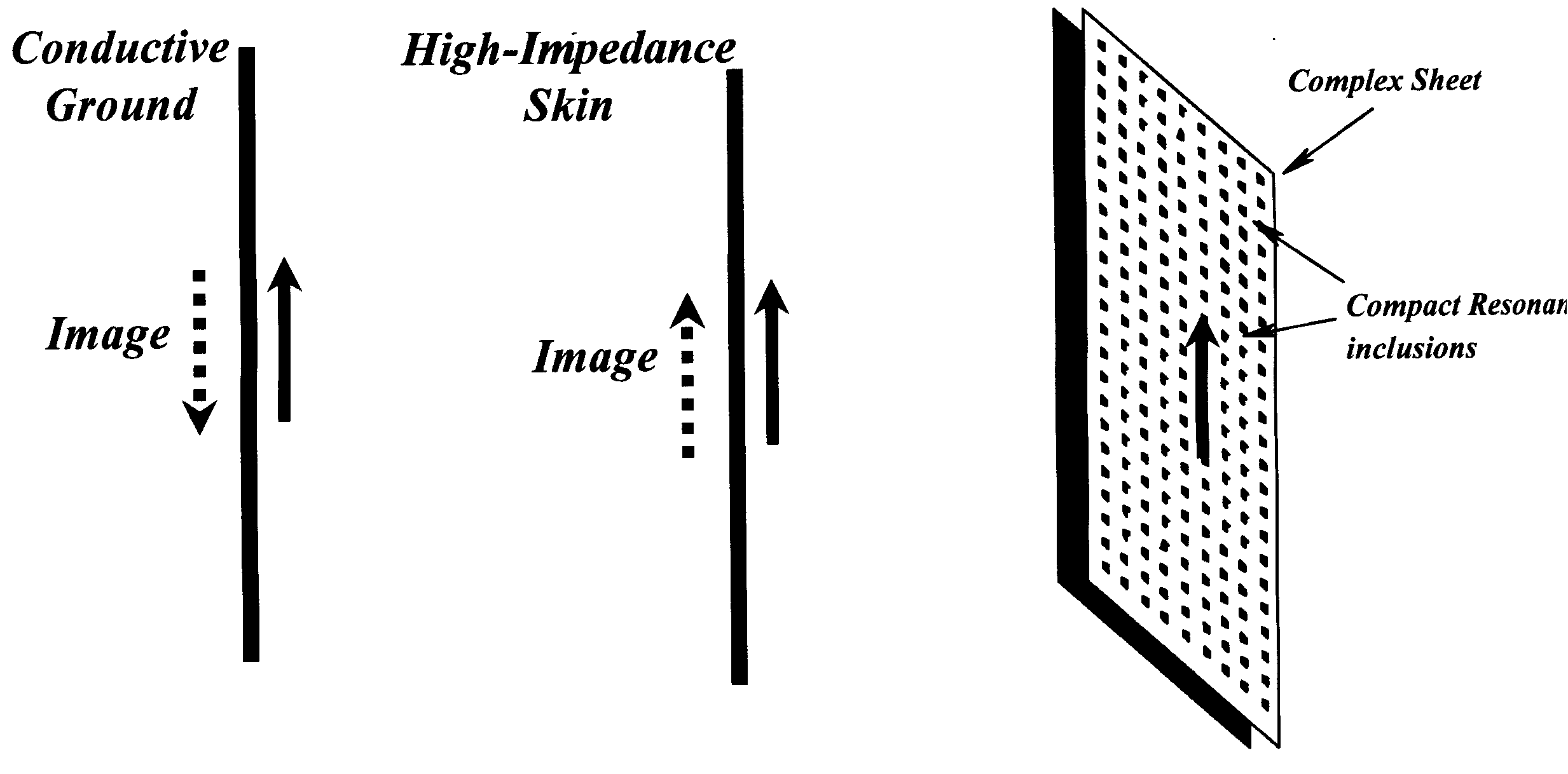 | Figure 1. Image current in conductive ground, HIS and complex sheet |
HIS are periodic structures that fixed or printed on a ground plane. The electromagnetic waves can propagate along their surface for some frequency ranges. These structures exhibit a frequency band gap similar to a band reject filter. In the gap, these composite materials act as homogeneous surfaces with high impedance. HIS belong to the class of Electromagnetic Band-Gap (EBG) structures. In antenna domain HIS act as a good ground plane or reflector and will improve antenna parameters such as gain, directivity and return loss. HIS have been initially introduced[4] In order to suppress surface waves in antenna applications (fig. 2). Fig 3 shows geometry and a piece of implemented HIS for proposed antenna. A 42.3×20.2cm fiberglass copper plate with thickness 2mm is used as HIS reflector. A matrix includes 12 rows and 25 columns of 15mm×15mm copper pieces with thickness 2mm is mounted to top surface. The gap between these pieces is about 2mm on each side. For creating a complete resonant circuit, before mounting in center of each copper piece some asymmetric holes with 4mm diameter at top side and 2mm on back side is drilled and filled of solder.In this method, handy implementing errors are reduced in compare with method used in[5].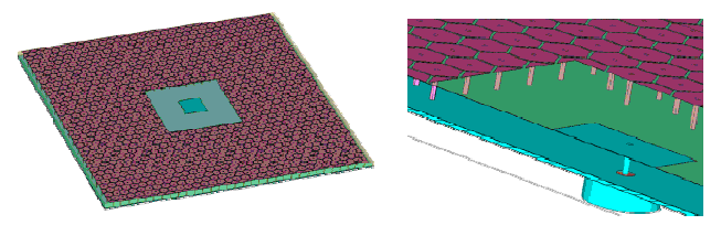 | Figure 2. Structures cantered with patch antenna and surrounding with HIS |
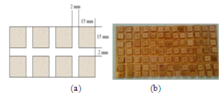 | Figure 3. (a) Top view of the high-impedance surface, showing a lattice of metal plates, (b) A piece of implemented HIS reflector |
2.2. ZAGI
A new class of antenna based on "slow-wave" structure called Zagi (Fig. 4)The antenna elements are formed from regularly bent wires; in this simple case you see just zigzags, but many other regularly bent structures are possible.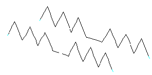 | Figure 4. Zagi structure |
In a "slow-wave structure", the speed of waves along the length of the structure is less than the speed of electromagnetic waves in free space. Therefore, at a given frequency f the wavelength (λ) along the axes is less than the free space wavelength c/f. To make a slow wave structure, it is necessary to increase L, C or both. Periodically bending the wires does increase L and C both and in this case the velocity reduces by a factor roughly equal to the total wire length divided by the total element length. So, these slow wave structures have increased inductance L and capacitance C per unit length. When two elements are brought close together, the coupling capacitance and mutual inductance (between the elements) are also increased. The adjustable parameters in parasitic antenna design process are the relative sizes of the driver and parasitic elements, the inter-element spacing, and the wire diameter. The resulting properties that we desire to adjust are the resonant frequency, gain, bandwidth and the f/b ratio.With the Zagi, we have additional adjustable parameters in design process: the number of serrations, the size of serrations, and the base angle of the basic triangles and the relative orientation of the serrations (relative to each other on the elements). These parameters give better control over the coupling and the consequent properties.There is no limitation for using rectangles or other regularly repeating shapes instead of saw tooth or serrated triangular in antenna elements. All of these should work nicely in slowing down the wave propagated along the wires and may well be superior to the ones discussed herein. Periodically loaded wires have great advantages over pseudo-fractal or randomly bent wires, in this situation the transmission line parameters do not fluctuate along the elements. We can achieve periodic perturbation with side stubs instead of bending wires. This method gives us many adjustable parameters in comparison with general method. This new concept in antenna design takes advantage of slow wave propagation in order to create antennas with increased coupling relative to rod elements and has the ability to change the coupling regard to design needs. Using this method has many advantages such as improving f/b, size and bandwidth of antenna and the cost of that is a minor increase in complexity.Due to the ability to vary the coupling between elements by varying their shapes, we have the ability to design ideal elements for any given purpose.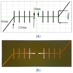 | Figure 5. (a) Antenna model and its dimensions, (b) Implemented antenna |
The overall length of antenna is about 405mm; the lengths of diagonal stubs are 95 mm, angle between diagonal stubs and central stubs is 45 degree, length of central gap is 20 mm, central stubs are 125mm and right stubs are 55mm. All lines have 5 mm wide. Frequency range for antennas is 300 to 2400 MHz. fig 5 shows antenna geometry and prepared antenna.
3. Material and Method
For comparing using HIS instead of ordinary reflector in Zagi antenna a general plate zagi antenna is prepared and tested with and without HIS reflector.For validating result and comparisons both antenna dimensions, implemented procedures, simulation software and test conditions are similar. Radiation pattern is considered as main factor to compare these antennas. The simulation software is 4nec2 v5.6.10. Simulation frequencies choose 600MHz, 800 MHz and 2GHz for illustrating antenna improvement in all frequencies. In sweep simulations the Band width chooses 300MHz to 2400MHz. In the mean time SWR as a sub factor in simulation process is calculated and compared in two antennas.
4. Result
4.1. Simulation Result
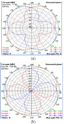 | Figure 6. (a) Simulation result of Plate ZAGI antenna without HIS, (b) with HIS, F= 600MHz. |
The simulation results for 600MHz is shown in fig 6. The total gain in ordinary reflector is about -9dB that increase to 9.88 dB in HIS. This improvement is very considerable. In the mean time the H and E plane in proposed antenna is very similar to ideal form. The vertical and horizontal gain in antenna with HIS completely decreases to zero in edge between lobes (for example [135° 150°] for horizontal and [45° 60°] for vertical gain) but this situation is very poor in antenna with ordinary reflector. These results are completely approved in 800MHz and 2GHz.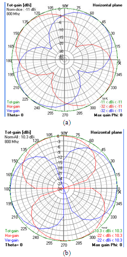 | Figure 7. (a) Simulation result of Plate ZAGI antenna without HIS, (b) with HIS, F= 800MHz |
The simulation results for 800MHz is shown in fig 7. The total gain in ordinary reflector is -11dB that increase to 10.3 dB in HIS. This increase is about 200% and very terrific. The vertical and horizontal gain similar to 600MHz completely decreases to zero in edge between lobes. The difference between minimum and maximum gain in proposed antenna is 32.3dB  but in general antenna this difference is about 21dB.The simulation results for 2000MHz is shown in fig 8. The total gain in ordinary reflector is -11dB that increase to 8.48 dB in HIS. All results are similar to 600MHz and 800MHz and show the better performance of proposed antenna in compare with antenna without HIS.
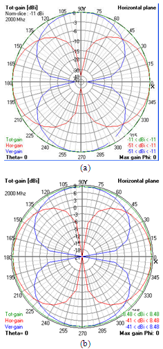 | Figure 8. (a) Simulation result of Plate ZAGI antenna without HIS, (b) with HIS, F= 2000MHz |
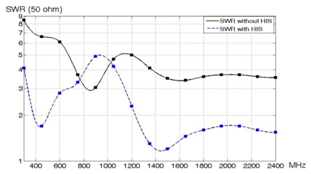 | Figure 9. SWR simulation result |
As a sub factor SWR in two antennas is calculated and the result shows in fig. 9. SWR for proposed antenna in all frequencies except a narrow band between 770MHz to 1030MHz is less than ordinary antenna and improved. This result shows that using HIS as a reflector improved some of antenna parameters not only the gain.
4.2. Experimental Result
For validating simulation result the proposed antenna similar to simulation model prepared and tested. The result shows in fig 10.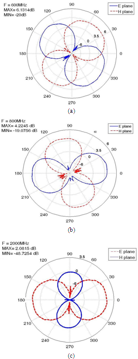 | Figure 10. Experimental result of Plate ZAGI antenna with HIS, (a) F= 600MHz, (b) F=800MHz, (c) F=2000MHz |
The results for 600MHz is shown in fig 10 (a). The total gain in proposed antenna is 6.13dB. This gain show a decrease about 3.7dB in compare with simulation result. Regard to prepare problems and experimental limitations, especially in high frequencies, this decrease is usual. The H and E plane in proposed antenna is very similar to simulation result. These results are completely approved in fig 10(b) 800MHz and fig 10(c) 2GHz. But gain decrease in these frequencies in compare with simulation result is more obvious. In 2000 MHz these decrease is about 6dB but antenna gain steel very better than ordinary reflector antenna.
5. Conclusions
A high impedance surface (HIS) reflector has been proposed for plate ZAGI antenna. It is demonstrated that HIS reflector improve performance of plate ZAGI antenna. This reflector causes to better gain, efficiency, SWR, etc in compare with ordinary antenna. In the mean time HIS correct the ripples of pattern. Good radiation patterns and acceptable maximum gain are obtained over whole of bandwidth. At last the proposed antenna prepared and experimental result confirm simulation result with an approximately good accuracy.
References
| [1] | Constantine A. Balanis, “Antenna Theory: Analysis and Design”, 3rd Edition. ISBN: 978-0-471-66782-7, April 2005. |
| [2] | Artificial Magnetic Conductor High-Impedance Surface for Compact Directive Antennas,www.ifh.ee.ethz.ch/field/semester.html, Institute für Feldtheorie und Höchstfrequenztechnik (IFH) 2007. |
| [3] | David Jefferies and Dan Handelsman, Archive VI article #87 of issue of antenneX magazine, www.antennex.com, March 2004. |
| [4] | Dan Sievenpiper, Lijun Zhang, Romulo F. Jimenez Broas, Nicolaos G. Alexopoulos, and Eli Yablonovitch, “High-impedance electromagnetic surfaces with a forbidden frequency band,” IEEE Trans. Microwave Theory and Techniques, vol. 47, No. 11, Nov. 1999, pp. 2059-2074. |
| [5] | D. Sievenpiper, “High-impedance electromagnetic surfaces,” Ph.D. dissertation, Department of Electrical Engineering, University of California at Los Angeles, Los Angeles, CA, 1999. |
| [6] | Studies on magneto-optical media and plastic substrate interfaces (Translation Journals style),” IEEE Transl. J. Magn. Jpn., vol. 2, Aug. 1987, pp. 740–741 [Dig. 9th Annu. Conf. Magnetics Japan, 1982, p. 301]. |
 Abstract
 Reference
 Full-Text PDF
 Full-Text HTML