-
Paper Information
- Previous Paper
- Paper Submission
-
Journal Information
- About This Journal
- Editorial Board
- Current Issue
- Archive
- Author Guidelines
- Contact Us
International Journal of Electromagnetics and Applications
2012; 2(3): 51-55
doi: 10.5923/j.ijea.20120203.06
Varying Slot Lengths Strip Loading Squared Dielectric Resonator Reflectarray
 Abstract
 Reference
 Full-Text PDF
 Full-Text HTML
A. M. Abd-Elhady 1, S. H. Zainud-Deen 2, A. A. Mitkees 3, A. A. Kishk 4
1Faculty of Engineering, Benha University, Egypt
2Faculty of Electronic Engineering, Menoufia University, Egypt
3Military Technical College, Egypt
4Department of Electrical Engineering, Concordia University, Canada
Correspondence to: A. M. Abd-Elhady , Faculty of Engineering, Benha University, Egypt.
| Email: |  |
Copyright © 2012 Scientific & Academic Publishing. All Rights Reserved.
a new type of dielectric resonator reflectarray composed of 529 elements covering an area of 276 x 276 cm2 is constructed. The unit cell consists of squared DRA supported on a strip with variable slot length, a dielectric layer and a conducting ground plane. The full phase of 360 degree of the array elements can be obtained by superposition two slot-strip sizes. Two types of feeding were analyzed, the first is center fed reflectarray while the second is offset feed to reduce the feeder blockage and as a result the antenna efficiency is improved. The antenna has 10% bandwidth for 1 dB gain variation is obviously wider than that of conventional reflectarray antenna while the offset fed reflectarray provide better far field pattern with back lobes reduction by -5 dB and side lobe by -2 dB. A rectangular X- band pyramidal horn was used in both reflectarrays which have 23 x 23 elements of with cells separation of 12 mm that less than 15 mm (lambda/2) for avoiding grating lobes. CST microwave studio©(finite integral technique) package is applied and compared with microstripes© package (transmission line technique) with good agreements between them. The mutual coupling between the feeding horn and the elements of the reflectarray are considered. At 10 GHz, the antenna provides a 3-dB beamwidth of 6 degree with a gain of 28 dB. The antenna bandwidth within 1dB gain variation is found to be 13% and aperture efficiency of 59%.
Keywords: DRA, Strip Loaded DRA , Reflectarray, Planar Array
Article Outline
1. Introduction
- The conventional parabolic reflectors are generally bulky in size and large in mass due to the curved reflecting surfaces. Recently, microstrip reflectarrays are found to be very attractive aperture antennas because of their planar structure and simple feeding[1]. Its advantage over a conventional planar microstrip phased array is a low conduction loss, especially in a millimeter-wave region[2,3], because it uses a spatial-type beamforming network. However, its shortcoming is a narrow-band operation compared with the conventional parabolic reflector. Usually, the required phase value to compensate for the different paths of the wave from the feed horn to each array element is only achieved at the center frequency within a range of 360o. Each element phase can be adjusted to produce a required phase over the aperture and control the main beam orientation. Usually, the dynamic range of the phase shift in a single-layer reflectarray is less than 360o, and the complete compensation is only for central frequency, which restrict the application to the large-aperture and/or wideband reflectarray. The problem of narrow-band operation of single layer patch reflectarrays can be overcome by employing multi-layer variable size patches[4,5]. The use of stack patches improves the phasing range of the individual elements (to about 450° for two layers) by using dual patch sizes, the upper bigger patch is resonated for the lower frequency while the smaller patch for the upper frequency. That technique broaden the bandwidth by superposition the two bandwidths. That offers lower phase slopes and leads to an increased operational bandwidth of the entire array antenna. A new dual layer cell is designed with wide phase range than dual layer patch reflectarray[6]. Another way for extending the bandwidth of the reflectarray, a patch supported on variable slot length is employed as the element of reflectarray, where the length of slot determines the reflection phase from the element for compensating the ray-path difference from the feed[7-11]. Overcoming the feed blockage that degrade the radiation efficiency of antennas as blocking by horn feeder some of reflected field, An offset reflectarray was designed using variable patch sizes[12]. The mutual coupling between microstrip elements printed on standard substrates becomes significant; in addition, the conductor and surface wave loss are severe. To overcome these limitations, other candidate, dielectric resonator antennas (DRA) have been introduced due to their low loss, relatively wide bandwidth, high radiation efficiency and low mutual coupling. These reflectarray antennas realized by rectangular and crossed dielectric resonator for linear polarization[13] which supported by strip for gain improvement while a Ka-band variable DRA reflectarray lengths supported on substrate of same dielectric constant of DRA was designed[14]. A X-band rectangular DRA and circular polarization at X-band[15] are investigated. Dual DRA sizes supported on ground plane with variable slot lengths is illustrated in[16] for getting full phase cycle using superposition. Aperture coupled DRA with variable strip line at X-band was designed with good performance in radiation patterns and total efficiency[17]. In this paper, slot-loading of rectangular dielectric resonator elements reflectarray in X-band is investigated. A reflectarray antenna consists of elements of rectangular dielectric resonator (DRA) with slot loading of different lengths is proposed for bandwidth enhancement. Fixed DRA size supported on strip conductor with two slot widths are available to tune the phase of each element in the reflectarray so that a full 360 degrees phase shifts can be achieved by superposition. Two structures are presented in that paper. The first is center fed reflectarray while the second is offset feed for decreasing the feeder blockage . The antenna has 10% bandwidth for 1 dB gain variation is obviously wider than that of conventional reflectarray antenna while the offset fed reflectarray provide better far field pattern with back lobes reduction by -5 dB and side lobe by -2 dB. A rectangular X band pyramidal horn was used in both reflectarrays which have 23 x 23 elements of with cells separation of 12 mm that less than 15 mm (lambda/2) for avoiding grating lobes. The analyses are carried out using CST microwave studio(FIT)[19] and Microstripes package (TLM)[18] with good agreements between them.
2. Simulation Analysis
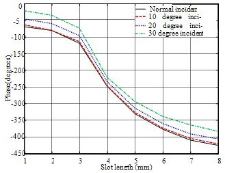
- A DRA reflectarray with variable slot loading length supported on dielectric substrate with conducting strip is constructed as shown in Figure 1. The unit cell consists of squared DRA, with length L, width W, height H, strip conductor of Lstrip x Wstrip with slot of length Lslot and width Wslot, a dielectric layer of thickness h, and a conducting ground plane. The bottom conducting plate is acting as a reflector to reduce the back radiation and improve the front to back ratio of the main beam. In order to determine the relation between the reflected phase and the selected parameters, a unit cell in an infinite periodic structure is considered with normal plane wave incidence. The design center frequency is considered 10 GHz. Figure 2 shows the phase variations versus the selected parameters. Two behaviours can be observed in Figure 2a: for 0 < Ls < 5 mm with L = W = 5 mm and slot width Ws = 0.6 mm, a 240o phase range can be obtained; for 5 < Ls < 8mm with L = W = 10 mm, another 120o phase range is reached. The complete phase 360o is obtained by superposition as shown in Figure 2b. FIT method (present method), the transmission line (TLM) method and commercial HFSS software[20] are used to investigate the performance of the antenna for the variation of the phase of the reflection coefficient against the slot length. The phase of the reflection coefficient for different frequencies as a function of DRA element length is computed and found to achieve 10 % bandwidth, which is corresponding to phase variation of ± 45o of the phase at 10 GHz for the middle size length as shown in Figure 3. The phase of reflection coefficients as a function of the plane wave angle of incidence is also predicted. The phase variation due to the angle of the incidence plane wave between normal incidence and 30o is found to be less than 90o as illustrated in Figure 4. Therefore; phases of the reflection coefficient due to normal plane wave incidence on a periodic infinite array are used to design the reflectarray and found to be sufficient as will be seen later. Considering the array on the x-y plane illuminated by a feed horn, the required phase distribution, Φ(xi, yi), at each element of the array to collimate a beam in the (θo, φo) direction is determined as:
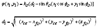 | (1) |
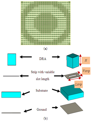 | Figure 1. DRA layout reflectarray a) Strip layer view b) Cell view |
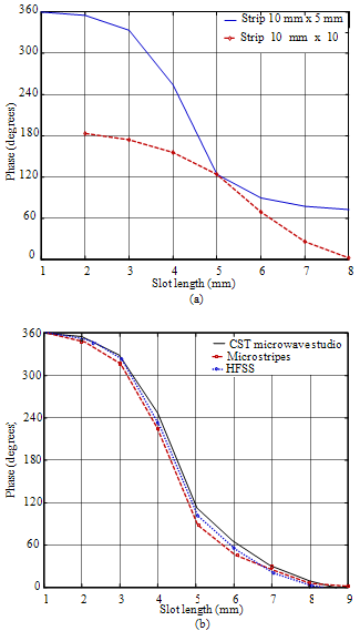 | Figure 2. Reflection coefficient phase versus DRA with variable slot length a)Super position b) Comparison |
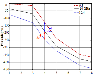 | Figure 3. Variation of reflected phase versus length at different frequencies |
 | Figure 4. Reflection coefficient phase versus variable length for different oblique angles |
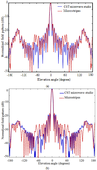 | Figure 5. Reflected Field patterns of DRA reflectarray at 10 GHz with main beam at = 0o a) YZ plane( E plane ) b) XZ plane(H plane) |
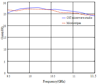
 | Figure 6. Gain versus frequency |
 | Figure 7. Offset fed DRA layout reflectarray |
3. Center Fed Reflectarray
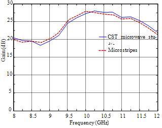
- The feed position is at xfo = 0 mm, yfo = 0 mm and zfo = 345 mm, with respect to the reflectarray center. The array is 23 x 23 unit cells. The reflectarray size was 276 x 276 mm2 with elements spacing of 12 mm and the focal length-to-diameter ratio F/D = 1. The layout of the DRA elements and their relative sizes are shown in Figure 1. Pyramidal horn of dimensions 60 x 30 mm2 is used. The radiation patterns of the designed reflectarray at 10 GHz are shown in Figure 5.The accuracy of the radiation patterns are verified by comparing the results of the present method with those from the TLM method.The radiation patterns has a 3-dB beamwidth of 8o and a peak gain of 28 dB at θ = 0o. The antenna gain versus frequency is shown in Figure 6 indicating 10% bandwidth with gain variations of 1 dB.
4. Offset Fed Reflectarray
- According to the center fed reflectarray, the horn block some of reflected field and as a result, the total efficiency of reflectarray was degraded. An offset fed reflectarray was designed to minimize the feeding blockage. The feeder is at position of xfo = 0 mm, yfo = 108 mm, zfo = 260 mm that make 22o feeder tilting angle with respect to the reflectarray center. The array had 23 x 23 unit cells. The reflectarray size was 276 x 276 mm2 with elements spacing of 12 mm. The layout of the DRA elements and their relative sizes are shown in Figure 7. The radiation patterns of the designed reflectarray at 10 GHz are shown in Figure 8.The gain verification figure is shown in Figure 9. The gain 1 dB bandwidth is about 9%.The accuracy of the radiation patterns are verified by com-paring the results of the two full wave package with good agreement.
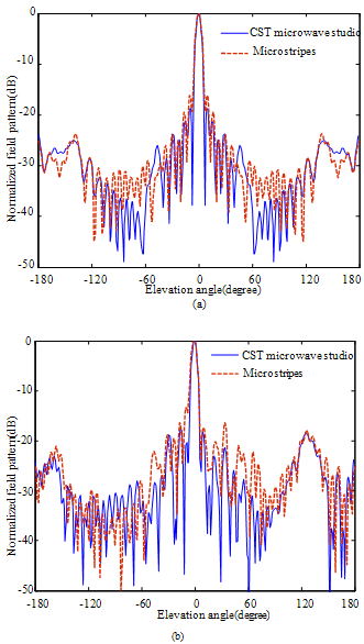 | Figure 8. Reflected Field patterns of DRA reflectarray at 10 GHz with main beam at = 0o a) YZ plane(E plane) b) XZ plane(H plane) |
 | Figure 9. Gain versus frequency |
5. Conclusions
- Slot-loading squared DRA elements reflectarray antenna was designed for linear polarization at X-band. The antenna was simulated by two feeding ways, one is center fed while the second is offset fed . Both arrays was fed by linearly polarized pyramidal horn. The cell reflection phase complete period was obtained by superposition of two strips sizes with variable slot lengths. The array cells were 23 x 23 elements reflectarray with area of 276 x 276 mm2. The finite integration technique was used to compute the radiation patterns and the gain of the antenna. The method was verified by comparing the results with transmission line method and was found to be efficient and accurate for these analyses.