-
Paper Information
- Next Paper
- Previous Paper
- Paper Submission
-
Journal Information
- About This Journal
- Editorial Board
- Current Issue
- Archive
- Author Guidelines
- Contact Us
International Journal of Electromagnetics and Applications
2012; 2(3): 41-45
doi: 10.5923/j.ijea.20120203.04
Wideband Stacked Rectangular Dielectric Resonator Antenna at 5.2 GHz
 Abstract
 Reference
 Full-Text PDF
 Full-Text HTML
G. D. Makwana 1, 2, Deepak Ghodgaonkar 2
1EC Department, Sankalchand Patel College of Engineering, Visnagar, 384315, India
2RF Laboratory, Dhirubhai Ambani Institute of Information and Communication Technology, Gandhinagar, 382007, India
Correspondence to: G. D. Makwana , EC Department, Sankalchand Patel College of Engineering, Visnagar, 384315, India.
| Email: |  |
Copyright © 2012 Scientific & Academic Publishing. All Rights Reserved.
This paper presents a design of stacked rectangular dielectric resonator antenna (RDRA) with wide bandwidth, in the range of 13.56 % is described. The antenna exploits two low-Q modes with overlapping bandwidths to achieve a wide continuous bandwidth. This is achieved using low-permittivity DRA volume placed on high permittivity DRA volume. The antenna consists of dielectric constant of 10 and 32, stacked vertically to obtain improved bandwidth as compared to the conventional RDRA. A 50 Ω microstrip line is used in the proposed antenna as a feeding mechanism. Physical parameters of stacked RDRA have been optimized by extensive simulations using Ansoft HFSS. The parameters of antenna are 17x7x4.56 mm3 with grounded substrate size: 80x50 mm2. The prototype is fabricated. Measured and simulated results are both in good agreement. The prototype antenna designed to operate in band from 5.0 to 5.7 GHz with measured gain at 5.2 GHz resonant frequency. The proposed antenna is suitable for wireless local area networks (WLAN) applications in 5 GHz frequency band (in the frequency range 5.15-5.35 GHz and 5.5-5.7 GHz). This stacked RDRA exceeds the bandwidth requirements for IEEE 802.11a WLAN applications within a required VSWR. Parametric studies of the stacked DRA are presented.
Keywords: Stacked Dielectric Resonator Antenna, Wireless Application, Microstrip line, WLAN
Article Outline
1. Introduction
- The rapid increase in the demand for wireless applications in the GHz range has led the research community to focus their attention on highly efficient antennas, which exhibit wide bandwidth and good radiation characteristics. The DRA introduced by Long et al. in 1983[1], could be used for such applications due to high radiation efficiency, light weight, and versatility in their shape and feeding mechanisms[2,3]. DRAs exhibit a wider impedance bandwidth and higher radiation efficiency, especially at millimeter- wave frequencies where the conductor losses of metallic patches are considerable. One of the most crucial issues of conventional DRAs is the dependence of their size and impedance bandwidth on the dielectric constant of material used in antennas. A DRA made from a low permittivity material would have a relatively large volume due to the inverse proportionality between effective wavelength and the square root of the permittivity. It would, however, exhibit a low radiation Q-factor and therefore a wide impedance bandwidth. On the other side, a high permittivity DRA would be small in size, with narrow bandwidth operation[3]. Choice of dielectric constant of material used in the DRA is crucially important for wideband operation with compact design of the DRAs.Applications in the wireless and mobile communication areas require the development of radiating elements, which have as compact/low profile and wideband as possible. Hence, a lot of research is directed towards an increase of the bandwidth of the DRAs while keeping the size compact/low profile. Towards this goal, the technique of merging modes has proven to be very beneficial[4, 5, and 6]. The basic concept relies on the excitation of multiple modes at nearby frequencies, so that an overall wide impedance bandwidth can be achieved. This can be done in two ways. One way is to combine the DRA modes with resonances of the feeding scheme. For instance, a simple cylindrical DRA (CDRA) described in[4] is fed from a microstrip line through two parallel bowtie slots. Here, an impedance bandwidth of around 33% is obtained through the excitation of the HEM11δ mode of the CDRA together with two modes from the resonant bowtie slots. The second way to achieve the merging of modes is through the design of the appropriate DRA geometry that results in the excitation of higher-order DRA modes at nearby frequencies. Conceptually this technique is relatively simple, but it nevertheless comes along with an important issue, which needs to be taken into account. Every mode has different radiation characteristics (radiation patterns, polarization) and therefore, a not well-controlled merging of modes technique would result in patterns of the DRA that vary with frequency. Examples of well-operating DRAs are given in[5,6], where the excitation of the fundamental TEx111 and the higher-order TEx113 modes of the rectangular DRA (RDRA) or the HEM11δ and HEM11Δ of the CDRA result in wide impedance bandwidth and stable broadside radiation patterns. The merging of the two modes of the RDRA is achieved through the careful dimensioning of the parallelepiped dielectric resonator. So, if the height of the RDRA is chosen to be much larger than its length and width, the TEx111 and TEx113 modes are found at nearby frequencies, which is in agreement with theory[6]. Some special geometry of DRAs such as conical, bi-conical, notch, triangle shape, have enhanced the impedance bandwidth[7-9] which are designed for broadband DRA. It was shown experimentally in[10-13] that stacking two DRAs on the top of each can increase an impedance bandwidth. But by this method, the DRA’s volume is a significant problem which may not maintain the major characteristic of low-profile and also it is not easy to fabricate. In[14], wide bandwidth operation has achieved by stacking of two different microwave materials in A-shape using P-shape parasitic strip. A coplanar waveguide (CPW) fed stacked rectangular resonator has reported in[15] to achieve broadband operation for millimeter underground communication. It was shown that wideband operation has achieved by stacked triangular dielectric resonator antenna for wireless applications in 5-6 GHz frequency range by a conformal patch feeding technique reported in[16]. It is shown theoretically in[17] that ultra wide bandwidth (10-dB return loss) achieved by stacking of high permittivity material on lower permittivity material of rectangular shape using coaxial feeding technique. In[18], the wide band has achieved using a full-length low- permittivity inset between a higher permittivity dielectric volume and a ground plane. This exploits multiple low-Q modes with overlapping bandwidths. The volume of such DRAs reduced by means of a finite planar conducting wall. This paper investigates stacked rectangular DRA gives wide bandwidth operation. Measured results are compared against the simulated results. This proposed antenna has wide impedance bandwidth. The measured co- polarization and cross polarization of radiation patterns over the impedance bandwidth (S11 < -10 dB) are compared each other. The measured return loss is presented and discussed.
2. Antenna Geometry
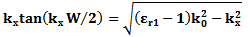
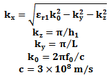
- Figure 1 shows the geometry of the proposed stacked rectangular DRA. A 50 Ω microstrip line is used (width = ), which is printed on top of the grounded substrate with thickness Hs = , dielectric constant of 2.5 and loss factor of 0.0017. Two DRA slabs (slab 1 & 2) are made from different permittivity εr1 and εr2 with same cross sectional area (L x W) but different heights h1 and h2 to form the stacked RDRA. The slab 1 is placed above the microstrip line for coupling, whereas the slab 2 is placed on the top of the slab 1 for electromagnetic coupling. The total height of stacked RDRA is h = h1 + h2. The size of ground plane is Ls xWs = 80 x 50 mm2. The fields equations of lowest order mode TExδ11 within RDRA are as per the (1). The design dimensions of the RDRA were determined using equations developed by dielectric waveguide model (DWM) given in [3].
 | (1.a) |
 | (1.b) |
 | (1.c) |
 | (1.d) |
 | (2) |
 To account the effect of two different dielectric materials on resonant frequency of the stacked RDRA, the DWM equations were modified by replacing slab 1’s height (h1) with an effective height (h) and dielectric constant of slab 1 (εr1) with effective permittivity (εeff)[13]. The effective height of the stacked RDRA is simple sum of slabs’ height
 | (3) |
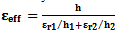 | (4) |
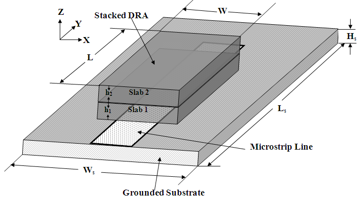 | Figure 1. Geometry of the proposed antenna |
3. Simulated Results
- Based on extensive simulation studies, design parameters of the stacked RDRA have been optimized. Slab 1 is made of microwave material with dielectric constant of 32 and thickness, h1, of . Slab 2 is made of several layers of microwave material with dielectric constant of 10.2 and thickness of each layer is . Cross sectional areas of both slabs are equal having dimension of length, L = 17 mm and width, W = 7 mm. Simulation studies are carried out for different height, h2, of the slab 2 on the slab 1 which has dimension of 17x7x3 mm3, to form a stacked RDRA. Open ended microstrip line is optimized for the return loss characteristic with reference to centre of the stacked RDRA for all cases. Simulated return loss characteristics for different heights of slab 2 are shown in Figure 2. Table 1 lists calculated resonant frequency (foc) and simulated resonant frequency (fos), return loss characteristics, and % of 6-dB impedance bandwidth. It is noticed that as height of slab 2 is increased from 00 mm to 2.34 mm in the step of 0.78 mm, the resonant frequency of the antenna is decreased, from 5.68 GHz to 5.00 GHz, whereas % of 6-dB impedance bandwidth is increased from 11.97% to 14.00%. This shows that by stacking of low permittivity microwave material on conventional dielectric resonator antenna made of high permittivity microwave material, the decrease in the resonant frequency and the increase in the impedance bandwidth can be achieved. The resonant frequencies of stacked RDRA are calculated base on equations (2, 3, and 4). Table 1 show that simulated resonant frequencies (fos) and calculated resonant frequencies (foc) have % of error in the order of 1 to 2.5. Based on these simulation results, physical design parameters: L = , W = , and h = have been chosen for the proposed antenna to excite at 5.2 GHz resonant frequency. Table 2 lists the design parameters of the proposed stacked DRA. Figure 3 shows simulated radiation patterns of the antenna at 5.2 GHz. For comparison simulation is carried out for conventional rectangular DRA with L = 17 mm, W = 7 mm, h1 = 4.56 mm, dielectric constant, εr1 = 32. Figure 3 shows simulated return loss characteristics of conventional RDRA and proposed stacked RDRA. It is observed that the conventional antenna resonants at 4.41 GHz with 8.50 % of 6-dB impedance bandwidth. This shows that by stacking different microwave materials with different permittivity, the wideband operation can be obtained.
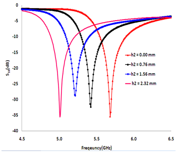 | Figure 2. Simulated S11 for different height of Slab 2 |
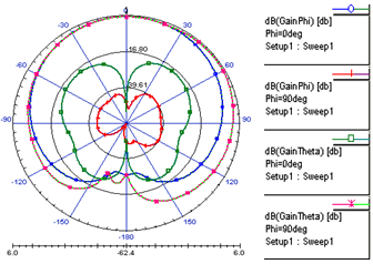 | Figure 3. Simulated radiation pattern at 5.2 GHz of the antenna |
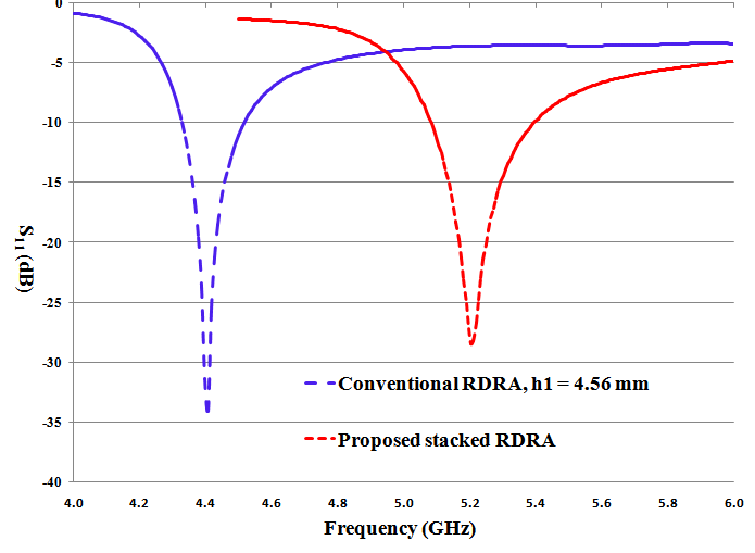 | Figure 4. Simulated return loss characteristics of conventional RDRA and the proposed stacked RDRA |
|
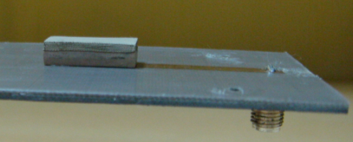 | Figure 5. Photograph of the fabricated antenna |
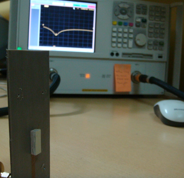 | Figure 6. Experiment setup with the proposed antenna |
4. Measured Results and Discussion
- The proposed antenna is fabricated as per the parameters given in Table 2. Figure 5 shows the photographs of the fabricated antenna. And Figure 6 shows the experiment setup for measurement of return loss characteristics of the antenna. The return loss characteristic of the antenna is measured by N5230A PNA series network analyzer. The measured and simulated return loss characteristics of the antenna are shown in Figure 7. Comparison of measured and simulated performances of the proposed antenna is listed in Table 3. From Figure 7 and Table 3, it is noticed that measured results are in excellent agreement with simulated results. The antenna has a 6-dB return loss bandwidth of 710 MHz (5.01 GHz to 5.72 GHz) at its resonant frequency of 5.23 GHz. The radiation patterns of the antenna are measured in an anechoic chamber. The co and cross polarization patterns in the E- plane and H- plane of the antenna are presented at resonant frequency in Figure 8 and Figure 9 respectively. There is good agreement between simulated and measured radiation patterns. It shows that the antenna has broadside radiations. The proposed antenna has linear polarization over the said bandwidth. The proposed antenna shows a cross polarization level better than -20 dB at the resonant frequency. The measured gain is 5.23 dBi at bore site for the resonant frequency. It is in good agreement with simulated gain.
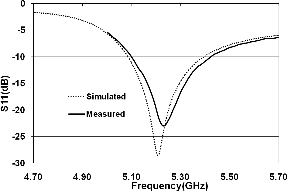 | Figure 7. Measured and simulated return loss characteristics of the antenna |
|
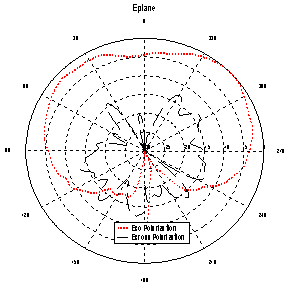 | Figure 8. Measured E- plane radiation patterns at 5.23 GHz |
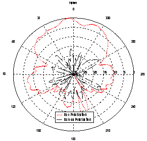 | Figure 9. Measured H-plane radiation patterns at 5.23 GHz |
5. Conclusions
- In this paper, we have demonstrated that the bandwidth of rectangular DR antenna can be increased substantially by placing low-permittivity DR volume on high permittivity DR volume. A simple microstrip fed stacked rectangular DRA operated at 5.2 GHz has been proposed. It has 6-dB return loss bandwidth of 710 MHz with good linear polarized radiation patterns. Frequency range of the antenna is from 5.0 GHz to 5.72 GHz. It has cross polarization level better than -20 dBi. The antenna is made from two different materials to achieve the benefit of compact size and wider bandwidth operation. Due to absence of conductor losses, the proposed antenna has high radiation efficiency. Fabrication cost is reduced because of simple microstrip feeding. Considering these benefits, the antenna is proposed for WLAN applications, MIMO wireless systems, Wi-Fi, cellular phones, and GPS systems.
ACKNOWLEDGEMENTS
- The authors would like to thank Dr. K. J. Vinoy, Microwave Laboratory, Indian Institute of Science, Bangalore, India for his continuous support and guidance for this work. He provides require microwave materials to fabricate the prototype and guide to carry out measurement of various parameters to complete the work.
References
| [1] | Long S. A., McAllister M.W., and Shen L.C., “The resonant cylindrical dielectric cavity antenna”, IEEE Transaction on Antennas and Propagation, Vol. 31, No. 3, pp. 406-412, 1983. |
| [2] | Mongia R. K. and Ittipiboon A., “Theoretical and experimental investigation on rectangular dielectric resonator antennas”, IEEE Transaction on Antenna and Propagation”, Vol. 45, No. 9, pp. 1348-1356, 1997. |
| [3] | Petosa A., Dielectric Resonator Antenna Handbook, Artech House, 25007. |
| [4] | Almpanis G., Fumeaux C. and Vahldieck R., “Novel broadband dielectric resonator antenna fed through double-bowtie- slot excitation scheme”, ACES Journal, Vol. 22, No. 1, pp. 97-104, 2007 |
| [5] | Li B., and Leung K.W., “Strip-fed rectangular dielectric resonator antennas with/without a parasitic patch”, IEEE Transaction Antenna and Propagation”, Vol. 41, No. 10, pp. 1390-1398, 1993. |
| [6] | Chair R., Kishk A. A., and Lee K. F., “Wideband simple cylindrical dielectric resonator antenna”, IEEE Microwave and Wireless Components Letters, Vol. 15, No. 4, pp. 241-243, 2005. |
| [7] | Almpanis G., Fumeaux C., and Vahldieck R., “Novel broadband dielectric resonator antenna fed through double-bowtie-slot excitation scheme”, ACES Journal, Vol. 22, No. 1, pp. 97-104, 2007. |
| [8] | Li B. and Leund K.W., “Strip-fed rectangular dielectric resonator antennas with/without a parasitic patch”, IEEE Transaction of Antenna and Propagation”, Vol. 41, No. 10, pp. 1390-1398, 1993. |
| [9] | Chair R., Kishk A.A., and Lee K.F., “Wideband simple cylindrical dielectric resonator antenna”, IEEE Microwave and Wireless Components Letters”, Vol. 15, No. 4, pp. 241-243, 2005. |
| [10] | Kishk A. A., Zhang X., Glisson A. W., Kajfez D., “Numerical analysis of stacked dielectric resonator antennas excited by a coaxial probe for wideband application”, IEEE Transaction on Antenna and Propagation, Vol. 51, No. 8, pp. 1996-2006, 2003. |
| [11] | Kishk A. A., Ahn B., and Kajfez D., “Broadband stacked dielectric resonator antennas”, IEEE Electronics Letters, Vol. 25, No. 18, pp. 1232-1233, Aug, 1989. |
| [12] | Rocha H. H. B., Freire F. N. A., Sohn R.S.T.M., da Silva M.G., Santos M.R.P., Junqueria C.C.M., Cordaro T., and Sombra A.S.B., “Bandwidth enhancement of stacked dielectric resonator antennas excited by a coaxial probe: an experiment and numerical investigation”, IET Microwave Antennas Propagation, Vol. 2, No. 6, pp. 580-587. 2008. |
| [13] | Petosa A., Simons N., Siushansian R., Ittipiboon A. and Cuhaci M., “Design and analysis of multisegment dielectric resonator antennas”, IEEE Transactions on Antennas and Propagation, Vol. 48, No. 5, May 2000, pp. 738-742. |
| [14] | Khalajmehrabadi A., Rahim M. K. A., Khalily M., “Dual band double stacked dielectric resonator antenna with a P- shape parasitic strip for circular polarization”, Presented at IEEE International on RF and Microwave Conference (RFM), 2011, pp. 444-447. |
| [15] | Coulibaly Y., Nedil M., Talbi L, Denidni T. A., “Design of mm-wave broadband CPW- fed stacked dielectric resonator antenna for underground mining communication”, Presented at IEEE International Symposium on Antennas and Propagation Society, 2010, pp. 1-4. |
| [16] | Kumari R., Parmar K., Behera S. K., “Conformal patch fed stacked triangular dielectric resonator antenna for WLAN applications” , Presented at International Conference on Emerging Trends in Robotics and Communication Technologies (INTERACT), 2010, pp. 104-107. |
| [17] | Ge Y., Esselle K. P., “A dielectric resonator antenna for UWB applications”, Presented at IEEE International Symposium on Antennas and Propagation Society, 2009, pp. 1-4. |
| [18] | Ge Y., Esselle K. P., Bird T.S., “Compact dielectric resonator antennas with ultra wide 60% - 110% bandwidth”, IEEE Transaction on Antennas and Propagation, Vol. 59, No. 9, 2011, pp. 3445-3448. |