-
Paper Information
- Next Paper
- Previous Paper
- Paper Submission
-
Journal Information
- About This Journal
- Editorial Board
- Current Issue
- Archive
- Author Guidelines
- Contact Us
International Journal of Electromagnetics and Applications
2012; 2(3): 33-40
doi: 10.5923/j.ijea.20120203.03
Experimental Investigation of High Step-Up DC-DC Converter for Fuel Cell System
 Abstract
 Reference
 Full-Text PDF
 Full-Text HTML
S. Harikrishnan 1, K. C. Ramya 1, E.Narendran 1, D. Peter Michael 2
1Department of Electrical and Electronics Engineering, Rajiv Gandhi College of Engineering, Sriperumbudur, India
2Department of Electrical and Electronics Engineering, Ganadipathy Tulsi’s Jain Engineering College, Vellore, India
Correspondence to: S. Harikrishnan , Department of Electrical and Electronics Engineering, Rajiv Gandhi College of Engineering, Sriperumbudur, India.
| Email: |  |
Copyright © 2012 Scientific & Academic Publishing. All Rights Reserved.
This work aims to present experimental investigation of a high step-up DC-DC converter for fuel cell system. The proposed converter comprises of an input-current doubler, an output-voltage doubler, and an active-clamp circuit. The input-current doubler and the output-voltage doubler both provide much higher voltage conversion ratio by using a low turn ratio transformer. The low turn ratio increases the overall efficiency. A series resonant circuit of the output voltage doubler removes the reverse recovery problem of the rectifying diodes. The active-clamp circuit clamps the surge voltage of switches and recycles the energy stored in the leakage inductance of the transformer. Simulation has been carried out for the proposed converter with the help of OrCAD software. Experimental results show that the better performance of the converter is achieved at an input voltage of 30V.
Keywords: Series Resonant Circuit, Active Clamp Circuit, Input-Current Doubler, Output-Voltage Doubler
Article Outline
1. Introduction
- A step-up DC-DC converter comprises of a direct current power source, an inductor, a first switching element, a second switching element, a smoothing capacitor, a driver controller for controlling switching ON or OFF the first switching element and the second switching element, and a control changing unit for changing a control operation of the driver controller according to a load current. A frequently used method for a power device to convert an input voltage to a desired output voltage includes power conversion at high efficiency by using a switching DC-DC converter. In multiport DC-DC converters, an effective duty ratio control method was implemented to extend the ZVS operating range when input voltages varied widely. Soft-switching conditions over the full operating range are achievable by adjusting the duty ratio of the voltage applied to the transformer winding in response to the dc voltage variations at the port[1].A new DC-DC converter for solid oxide fuel cell powered auxiliary power unit was developed. Here, the converter did not consider the leakage inductance of the transformer as a parasite and used it for energy transfer, thereby increasing the efficiency of the converter[2]. A new approach was developed in one research paper for analyzing the V-I characteristics of fuel cells stacks based on DC-DC converters. The measurement of the desired characteristic offuel cells included high speed of response, high fidelity and low cost. The obtained results had shown that all DC-DC topologies were not capable of reproducing thischaracteristic[3]. Another strategy was developed for an isolated boost full bridge converter to employ soft-commutating method and control scheme. Zero-voltage-switching(ZVS) was achieved for all the switches at the voltage-fed side inverter in boost mode operation[4].A single-stage current-fed full-bridge boost converter with power factor correction(PFC) and zero current switching (ZCS) for high voltage application was studied. The variable frequency control scheme with ZCS was employed to regulate the output voltage and achieve high power factor. The maximum power factor and efficiency obtained were 0.995 and 87.4 at full load condition with an input voltage of 220V[5]. A new active clamping ZVS pulse width modulation(PWM) current-fed half-bridge converter was designed and analyzed to ensure the higher operating frequency, smaller-sized reactive components, lower cost of production, easier implementation, and higher efficiency[6]. A dual series-resonant active-clamp dc-dc converter was presented to obtain high efficiency. This converter used an active-clamp technique which served to recycle the energy stored in the leakage inductance and provided zero-voltage turn-on switching. The voltage stresses of the main switch were clamped[7]. A novel two-stage step-up DC-DC converter was developed to increase the voltage from 24V to 270V for electric vehicle power system application. This device had the advantages of high power density, easy control, high efficiency, high transformer utilization, and fast dynamic response[8].To overcome limited voltage step-up ratio in a classical boost converter, non-isolated high step-up technique based on isolated type converter was introduced. It was tested experimentally and the results showed the better performance[9]. Considering a high efficiency step-up converter with low switch voltage stress for fuel cell system applications in which input and output ripples were reduced and also higher voltage conversion ratio was achieved[10]. A novel high step-up DC-DC converter was introduced for flow-input-voltage fuel cell energy conversion applications. Here, a multi-windings coupled inductor and a voltage doubler were employed for achieving high step-up voltage gain[11].High step-up converter with coupled-inductor was experimentally studied as another strategy in which the closed-loop control methodology was introduced in the proposed scheme to overcome the voltage drift problem of the power source under the load variations. Resulting this, the proposed converter topology enhanced the voltage gain of a conventional boost converter with a single inductor, and dealt with the problem of the leakage inductor and demagnetization of transformer for a coupled-inductor-based converter[12]. A forward energy-delivered technique was presented to reduce the power loss in the step-up ZVS full-bridge converter. The forward energy-delivered circuit (FEDC) closely wound in the resonant inductor was able to alleviate the high ringing ripples incorporating in the primary current and delivered excess energy to the load during step-up conversion[13]. Hence, a high step up dc-dc converter with high voltage conversion ratio, low input current ripple and high efficiency is required. In this paper, experimental investigation of high step up DC-DC converter has been studied for assessing the simulation work of the same carried out in the past[14].
2. Conventional Method
- A conventional current-fed half-bridge converter has the input-current doubler function. Since the input current divides into two inductor currents, reducing the primary current of the transformer, the related conduction loss is reduced. However, this converter has several problems such as voltage spikes of switches resulting from the leakage inductance of the transformer, high-voltage stress of the rectifying diodes, and low power conversion efficiency.
2.1. Need for step-up DC–DC Converter
- Generally, the fuel cell stack has a low voltage and its current ripple must be small. Therefore, a high step-up dc–dc converter with high voltage conversion ratio, low input-current ripple, and high efficiency is required.
2.2. DC - DC Converter
- DC to DC converter is an electronic circuit which converts a source of direct current (DC) from one voltage level to another. Every electronic system is designed to operate from a supply voltage, which is usually assumed to be constant. A voltage regulator provides this constant DC output voltage and contains circuitry that continuously holds the output voltage at the design value regardless of changes in load current or input voltage, assuming that the load current and input voltage are within the specified operating range for that regulator.In portable systems, the input voltage is often obtained from a battery. DC to DC converter type regulators receive such fixed DC voltage as input and produce the desired voltage as output which could be higher or lower than the input voltage. DC to DC converter accepts a fixed DC input voltage and produces a DC output voltage at a different level than the input. They are also used to provide noise isolation, power bus regulation, etc.
3. Proposed Method
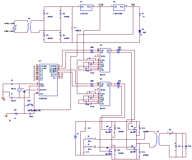
- Active clamping current-fed half-bridge converters have been presented to solve the above mentioned problems. Its active-clamping circuit clamps the surge voltage of switches and recycles the energy stored in the leakage inductance. However, the reverse-recovery problem of the output rectifying diodes still exists. In the current project a high-efficiency high step-up dc–dc converter is proposed for fuel cell power systems. The proposed system consists of an input-current doubler, an output-voltage doubler, and an active-clamp circuit. The input-current doubler and the output-voltage doubler provide a much higher voltage conversion ratio without using a high turns ratio in the transformer and increase the overall efficiency. A series-resonant circuit of the output-voltage doubler removes the reverse-recovery problem of the rectifying diodes. The proposed dc–dc converter has low conduction loss in the primary side, since the input-current doubler divides the input current into two inductor currents, reducing the primary current of the transformer, and the primary switches with the active-clamp circuit have low ON-resistance by reducing voltage stress.The input-current doubler and the output-voltage doubler provide a much higher voltage conversion ratio without using a high turns-ratio transformer and increase the overall efficiency. The output-voltage doubler doubles the conversion ratio and the voltage stress on rectifying diodes is confined to the output voltage. This voltage doubler provides a series-resonant circuit that consists of a transformer leakage inductance and a resonant capacitor. Then, the zero-current turn-OFF of the output rectifying diodes is achieved, and the reverse-recovery losses are eliminated.Voltage-fed converters are often used in the step-up dc–dc converter for fuel cells. However, these voltage-fed converters may not be optimal due to large input-current ripple. Reducing the input-current ripple in the voltage-fed converter requires an additional LC filter across the fuel cell stack, which lowers the power efficiency. Also, a high turns ratio between the primary and secondary sides of the high-frequency transformer is required. Current-fed converters decrease the input-current ripple by using an inductor. Current-fed converters have advantages of high voltage conversion ratio, low input-current ripple, and low conduction loss of switches. Several current-fed converters have been developed such as a current-fed push–pull converter, a current-fed full-bridge converter, and a current-fed half-bridge converter. The hardware implementation of the proposed high step-up DC to DC converter is shown below in fig. 1.
4. Simulation
- Simulation has become a very powerful tool in industry applications as well as in academics, nowadays. It is now essential for an electrical engineer to understand the concept of simulation and learn its use in various applications. Simulation is one of the best ways to study the system or circuit behavior without damaging it. The tools for doing the simulation in various fields are available in the market for engineering professionals.SPICE is a general-purpose circuit program that stimulates electronic circuits. The acronym SPICE stands for stimulation program with integrated circuit emphasis. Till now, PSPICE is available only on the mainframe computers. In addition that the initial cost of the mainframe computer is expensive and inconvenient for classroom use. SPICE, therefore, widens the scope for the integration of computer-aided analysis into electronic circuit courses at the undergraduate level. In 1984, microsim introduced the PSPICE simulator, which is similar to the Berkeley SPICE and runs on an IBM-PC or compatible. PSPICE therefore, widens the scope for the integration of computer aided circuit analysis into electronic circuits at the undergraduate level. The other versions of spice that will run on computers such as the Macintosh 2,V AX, SUN, and NEC are also available.
4.1. Types of Analysis
- PSPICE allows various types of analysis. Each analysis is invoked by including its command statement. For example, a statement beginning with the DC command invokes the DC sweep. The types of analysis and their corresponding (Dot) commands are described below.DC analysis is used for circuits with time-invariant sources. It calculates all node voltages and branch currents over a range of values, and their quiescent (dc) values are at the outputs. DC sweep of an input voltage/current source, a model parameter, or temperature over a wide range of values (.DC) determination of the liberalized model parameters of non linear devices (.OP) DC operating point to obtain all node voltages (.op) small-signal transfer function with small-signal gain, input resistance, and output resistance small-sign transient analysis is used for circuits with time-variant sources. It calculates all sensitivities (.SENS).All node voltages and branch currents over a time interval, and their instantaneous values are the outputs. Circuit behavior in response to time varying sources (.TRAN) DC and Fourier components of the transient analysis results (.FOUR) AC analysis is used for small-signal analysis of circuits with sources of variable frequencies. It calculates all node voltages and branch currents over a range of frequencies, and their magnitudes and phase angles are the outputs.
4.2. Simulation Tools
- Simulation of power electronic converters and can be done, either by (I) circuit oriented simulator (e.g. PSPICE, PSIM, TINA, electronics workbench, etc), or by (2) mathematical model based equation solvers using high level languages (e.g., C++, VISUALBASIC, etc.), or high level language based packages (MATLAB, MATHEMATICA, etc). In this we can use the circuit-oriented simulators also few software simulation tools are listed which are widely accepted by the engineering society, particularly by the electrical engineers. The simulation tools are in use in industries as well as in academic institution.
5. Results and Discussion
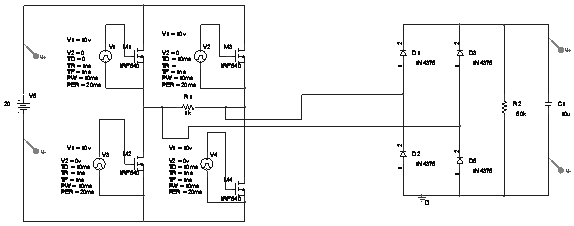
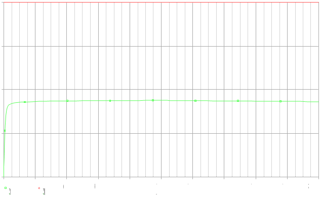
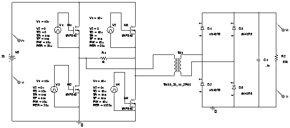
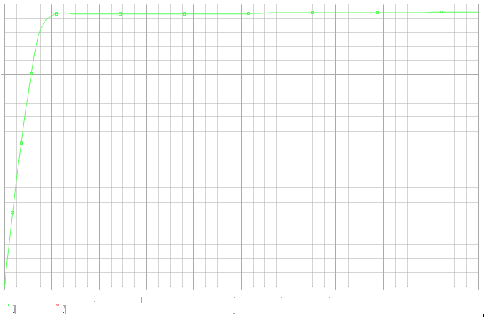
- Experimental investigations of different DC-DC converter responses are explained individually in the below section. Fig.2 demonstrates the circuit of Non-isolated DC-DC converter in which there is single phase power MOSFET based full bridge inverter as input section and single phase bridge rectifier as output section. The output voltage waveform of the Non-isolated DC-DC converter is seen in fig.3. From the fig.3, it is observed that the output voltage is less than the applied input voltage. This is due to ON state resistance incurred by the power MOSFETs.Fig.4 represents the circuit of isolated DC-DC converter consisting of single phase power MOSFET based full bridge inverter as input section, single phase bridge rectifier as output section and a high frequency transformer used as a isolator. Fig.5 shows the output voltage of isolated DC-DC converter. Due to presence of conduction losses in the power MOSFET, output voltage is less than that of input voltage. Fig.6 illustrates the circuit of current doubler circuit including single phase power MOSFET based full bridge inverter, inductors L1 and L2, and a high frequency transformer. Fig.7 represents the response of current doubler in which the output current has been doubled than that of the input current. The reason for this is that resonant components are connected in series with the inverter. Fig.8 shows the voltage doubler circuit comprising of single phase power MOSFET based full bridge inverter as input section, rectifier as output section and a high frequency transformer used as a isolator. Fig.9 represents the response of voltage doubler in which the output voltage has been doubled than that of the input voltage. Voltage spikes, switching losses and leakage losses have been eliminated by the active clamping circuit.
 | Figure 1. Hardware implementation of the proposed system |
 | Figure 2. Non-isolated DC/DC converter |
 | Figure 3. Output voltage waveform of Non-isolated DC/DC converter |
 | Figure 4. Isolated DC/DC converter |
 | Figure 5. Output voltage waveform of isolated DC/DC converter |
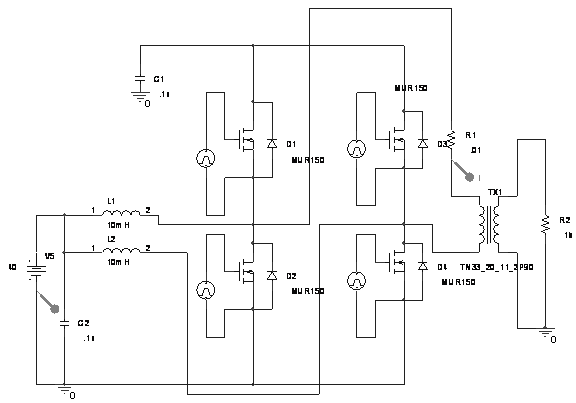 | Figure 6. Current doubler circuit |
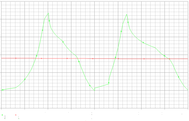 | Figure 7. Input current waveform of current doubler |
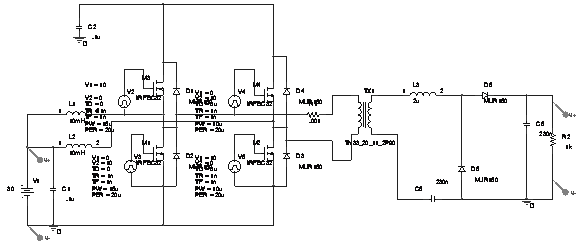 | Figure 8. Voltage doubler circuit |
 | Figure 9. Output voltage waveform of voltage doubler |
6. Conclusions
- A high step-up DC/DC converter proposed for fuel cell system was experimentally investigated. The proposed converter comprised of an input-current doubler, an output-voltage doubler, and an active-clamp circuit. The input-current doubler and the output-voltage doubler achieved a much higher voltage conversion ratio by using a low turn ratio transformer. The low turn ratio had increased the overall efficiency. Reverse recovery problem of the rectifying diodes was removed by a series resonant circuit of the output-voltage doubler. The active-clamp circuit clamped the surge voltage of switches and recycled the energy stored in the leakage inductance of the transformer. Experimental results proved that the better performance of the converter was obtained at an input voltage of 30V.
AcknowledgementS
- The authors would like to thank Mr. M. Gopi. B.E., Quality Manager, Voltech Manufacturing Company Limited, for his kind suggestions regarding the leakage inductance of the transformer.