-
Paper Information
- Next Paper
- Paper Submission
-
Journal Information
- About This Journal
- Editorial Board
- Current Issue
- Archive
- Author Guidelines
- Contact Us
International Journal of Electromagnetics and Applications
2012; 2(3): 16-23
doi: 10.5923/j.ijea.20120203.01
Characterization, Design and Optimization of Low-Profile Cavities for UWB Spiral Antennas
 Abstract
 Reference
 Full-Text PDF
 Full-Text HTML
N. Rahman , A. Sharma, M. N. Afsar
Department of Electrical and Computer Engineering, Tufts University, Medford, 02155, USA
Correspondence to: N. Rahman , Department of Electrical and Computer Engineering, Tufts University, Medford, 02155, USA.
| Email: |  |
Copyright © 2012 Scientific & Academic Publishing. All Rights Reserved.
In this paper, we present a methodology for developing very low profile, hybrid, cavity-backed UWB spiral antennas from a precision electromagnetic material characterization standpoint. Using our method, we have accurately characterized, designed and optimized the dimensions of a 2-18GHz, cavity-backed Archimedean spiral antenna. The simulation and measurement results show that the antenna demonstrates excellent axial ratio and gain-bandwidth performance while maintaining an absorptive cavity depth of only 0.625 inches. The procedure can be extended to the design and optimization of any low-profile spiral radiator required to operate over extremely broad frequencies.
Keywords: Low profile cavity-backed spiral antenna, Archimedean spiral, UWB, axial ratio, complex permittivity and permeability
Article Outline
1. Introduction
- In recent years, considerable research efforts have been placed on developing cavity-backed spiral antennas that have many useful applications in satellite communications, GPS tracking systems and modern avionics. These antennas radiate energy bi-directionally perpendicular to their plane. In most cases, a unidirectional pattern is preferred to minimize interference arising from an aircraft or satellite structure. It is also desired that the antennas are lightweight and of low profile. Therefore, simple spirals are often geometrically modified to obtain a more compact antenna, while a unidirectional beam is usually attained by introducing a lossy cavity that absorbs the back wave completely.Backing a spiral antenna with an absorbing cavity, however, restricts the radiation to one hemisphere at the expense of a 3dB reduction in the antenna gain. To address the matter, λ/4 reflecting cavities, cavities with special materials and parabolic reflectors are currently under investigation. Recent developments on 10-14GHz EBG ground plane backed Archimedean spirals, 6-12GHz meta-material inspired spirals, 3-10 GHz disk attached shallow cavities, and 0.36-6.83GHz spirals with parabolic reflectors have demonstrated reasonably low-profile geometries[1-4]. Most efforts, however, are relatively bandwidth limited and have not been able to address the needs of applications where bandwidths ≥ 10:1 are required with good circular polarization performance. Absorptive cavity-backed spiral radiators provide an effective solution for multiple SATCOM and SatNav services requiring consistent gain, uniformly matched input impedances and ≤3dB axial ratios across extremely wideband frequencies.2-18GHz spiral antennas operating at UWB frequencies are difficult to reduce to profiles lower than 1 inch in thickness[5,6]. This is due to the fact that the materials used in the cavities are predominantly dielectric in nature (µ≈1), and are relatively thicker than their magnetic counterparts. Magnetic absorbers on the other hand, attenuate EM waves through magnetic hysteresis loss and can be designed to be very thin microwave absorbers. Also, these materials can be produced as non-conductive absorbents since they are most often constructed from ferrites, and can be effectively used without creating a short circuit in the metallic cavity. Hence, magnetic materials offer an attractive choice for the design of shallow cavities. However, ferrite-based absorbers work best at frequencies below 2GHz. Their resonant properties tend to roll off after that. And to create dielectric loss at a lower frequency requires adding more metallic materials in the absorbent, which may create problems such as increased surface impedance in real time applications. Keeping these factors in mind, we have developed an effective way to construct low profile cavities by using a hybrid composite of magnetic and dielectric absorbing materials arranged in appropriate order and optimized for maximum radiation performance. The magnetic materials tailored to provide absorption at frequencies in the vicinity of 1-2GHz, significantly reduce the cavity depth. The dielectric absorbers, suitable for higher frequencies on the other hand, allow for gradual impedance taper in a multi-layer cavity arrangement. Successful design, optimization and performance verification of UWB antennas having frequency-dependent electromagnetic materials inserted in their cavities, however, can only be possible if the complete frequency responses of these materials are available with significant accuracy. Even though many wideband microwave measurement techniques have been developed for precision characterization of linear, dielectric materials, traditional methods often pose a challenge for magnetic materials, materials having both dielectric and magnetic characteristics, or non-reciprocal resonant materials such as meta-materialized structures. Hence, developing low-profile, absorptive, cavity-backed spiral antennas becomes contingent upon the availability of appropriate material characterization instrumentation and methodology that is capable of producing precise complex permittivity and permeability data, so that these material properties can be accurately replicated in simulation tools to ensure closest antenna pattern approximations prior to fabrication. In this work, we have attempted to provide a complete treatise for developing low-profile, UWB spiral radiators with hybrid absorptive cavities from a high-precision material characterization standpoint. We have exploited a precision waveguide-based measurement technique to obtain the broadband response of a representative set of magnetic and dielectric absorbents. The data thus acquired enabled us to develop a generalized design algorithm to design a UWB, 2-18GHz hybrid cavity comprising of both magnetic and dielectric materials and reduce its depth to 0.625 inch. We have demonstrated the efficiency of our procedure by fabricating a shallow cavity-backed, 2-arm, Archimedean spiral antenna where the measured results show very good gain-bandwidth performance.
2. Antenna Geometry and Absorbing Material Description
2.1. Spiral Configuration
- The antenna was simulated and fabricated with the following parameters: inner radius, r1 = 0.015 inch, outer radius r2 = 1.2 inch, number of turns N = 27 and spiral proportionality constant φs = 0.007 inch/radian (0.18mm/ radian). To verify the performance of the newly designed cavity, the radiation properties of a spiral antenna backed with the optimized, shallow cavity was then compared to that of a ≈1 inch deep, cavity-backed, standard Archimedean spiral antenna loaded with purely dielectric absorbing materials. The fabricated antenna is shown in Figure. 1.
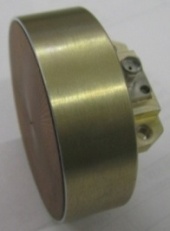 | Figure 1. 2-arm, Archimedean spiral antenna with a shallow cavity |
2.2. Absorptive Cavity configuration
- Using our design algorithm and optimization process as will be explained in the following sections, three constituent absorbing materials have been used in the construction of a multi-layer hybrid cavity. The front layer at the air-absorber interface (AN series, Emerson and Cumming) is a carbon-loaded polyurethane foam absorber which typically provides -20 dB insertion loss in frequencies above 3.5GHz but gave the closest impedance match to free-space. The middle layer (LS-10055, ARC technologies) is a flexible, low-density and high loss carbon loaded foam. The metal-backed 3rd layer is an iron-loaded, magnetic thermoplastic elastomer (WT-BPJA-010, ARC technologies) typically designed for attenuation in the +1GHz range. For a 2.4” diameter antenna aperture, the shallowest cavity depth that ensures 2-18GHz absorption for maximum gain-bandwidth performance is 0.625 inch including the air-gap between the radiator and the absorbing layers.
3. Characterization and Design of Low-Profile Cavities
3.1. Database of Absorbing Materials
- To develop a generalized design algorithm for low-profile cavities for any frequency range within the microwave spectrum, we first created a representative sample space of narrowband absorbing materials having both magnetic and dielectric properties and providing typical attenuation at different frequencies in the 2-40GHz range. 19 commercially available absorbing materials were selected to populate a database of materials available to configure a low profile spiral cavity. Our purpose was to adequately represent magnetic and dielectric materials in different frequencies. Any number and arrangement of materials can be used in general.
3.2. Characterization Method
- The absorbing materials having both dielectric and magnetic properties were characterized using a transmission- reflection (T/R) based automated precision rectangular waveguide technique developed at the Microwaves, Millimeter Waves and THz Laboratory at Tufts University. In this method, an Agilent Vector Network Analyzer was used to measure the S11 and S21 parameters when a sample of material was inserted inside a waveguide to form a two-port network. The method is based on the (T/R) technique introduced by Nicolson-Ross[7] and Weir[8], and the widely acclaimed formulations for transmission and reflection coefficients proposed by Baker-Jarvis[9]. However, in this technique, a precise methodology was used for the determination of electromagnetic properties of linear dielectric and magnetic materials of reasonable thickness. The method is capable of simultaneously determining the complex permittivity and permeability values for two-dimensional samples without requiring any guess parameter or having any phase ambiguity in the characterization process[10]. The high precision of our methodology has been previously demonstrated from measurement results of materials that are difficult to characterize. For instance, Aerogel materials have permeability and permittivity values very near to air. The characterization process successfully differentiated the material properties from air[11]. The proposed method also works very well to determine the permittivity and permeability of microwave materials at their resonant frequencies. The formulations are mathematically consistent with all prior work and the measured data has been experimentally verified to show precise and accurate results. The work has been recently extended to the characterization of meta-materialized structures and similar precision was obtained in determining the negative refractive index spectr [12,13].
3.3. Complex Permittivity and Permeability
- As indicated in the manufacturer’s data sheets, the materials under test have been tested for their attenuation and typical reflectivity based on normal incident wave as an indicator of their absorption capabilities. No information, however, was available as to how their material constitutive properties change with frequency. We derived the precise frequency dependent material properties from 2-40GHz using our measurement method for all materials in the database. The derived complex permittivity and permeability data is very reliable and not affected by the scattering voltage ratios. The resultant material properties for the three absorbing layers eventually selected for the composite structure, are shown in Figures. 2, 3 and 4.
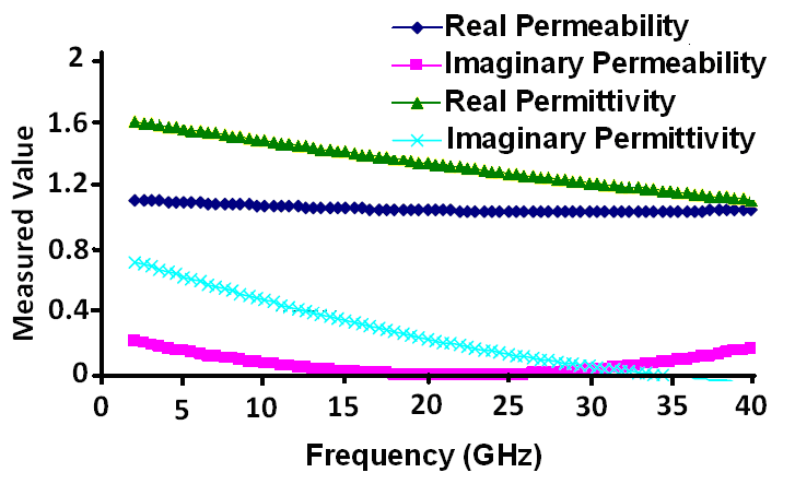 | Figure 2. Measured constitutive parameters for the first layer (AN-74) |
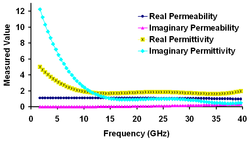 | Figure 3. Measured constitutive parameters for the middle layer (LS-10055) |
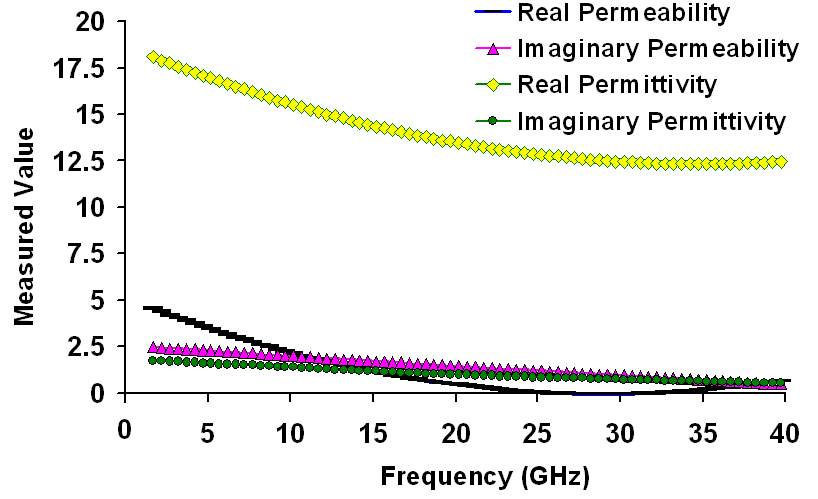 | Figure 4. Measured constitutive parameters for the third metal-backed layer (WT-BPJA-010) |
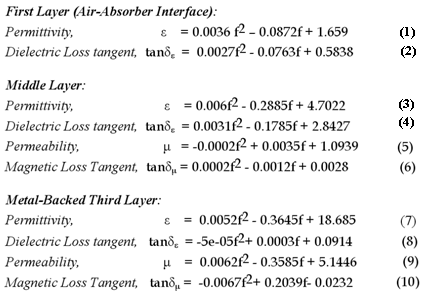
3.4. Equations Relating Material Properties to Frequency
- From the experimentally obtained data, we used curve fitting methods to obtain mathematical relations between material constitutive parameters and frequency. The equations for the real part of permittivity, permeability and the loss tangent (imaginary part over real part) of the materials enabled us to replicate the behavior of the absorbing materials in FEKO with their frequency dependent characteristic equations incorporated in the CADFEKO modeler. The derived equations for the three layers are given from (1) through (10), where f is the frequency in GHz.
|
3.5. Reflectivity Analysis
- To determine the thickness of an absorbing layer at the frequency of maximum attenuation, the reflection spectrum of each sample was analyzed from 2 to 40GHz. The position of the reflection minima as a function of thickness for each metal-backed absorber indicated the approximate frequency range and thickness for maximum absorption inside the absorber. For instance, Figure. 4 shows the reflection coefficient of sample WT-BPJA-010 as a function of frequency. It is a narrowband absorber and exhibits strong absorption at 5GHz when the thickness is 0.18cm.
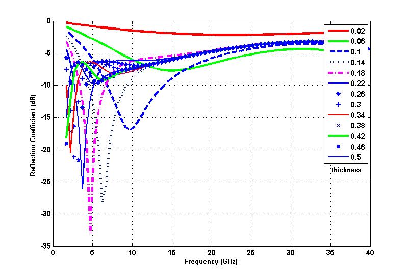 | Figure 5. Reflection coefficient of BPJA010 as a function of frequency. It is a narrowband absorber and exhibits strong absorption at 5GHz at 0.18” thickness |
3.6. Algorithm for Thin Composite
- With the goal of designing a sufficiently low profile spiral cavity, we populated our database with the most accurate and precise complex permittivity and permeability information and thickness of maximum attenuation from 2-40GHz for all dielectric and magnetic absorbers in our sample space. The materials were then categorized in frequency subdivisions according to their reflection minima. If a sample showed different absorption peaks for different thicknesses, it was repeated and included in all frequency subdivisions. A computer code requested user input for operational bandwidth and maximum allowable cavity depth of the spiral antenna. The program generates a list of suitable materials for the hybrid composite and the corresponding thickness values of each material determined from the reflectivity analysis that would provide absorption in the requested frequency range. The code also ensured that if a lower frequency in the vicinity of 2GHz is requested, then at least one layer of magnetic absorber is selected within the specified bandwidth and that the total thickness does not exceed the specified the cavity depth. For all possible arrangements of placing M layers of materials in the composite [with M factorial (M!) possible arrangements], the equivalent impedance and reflection coefficient at the front surface is calculated from the material data. The arrangement that results in the shallowest possible cavity, reflection coefficient ≤-10dB throughout the operational bandwidth and front-end input impedance ≈377Ω is selected as an approximate cavity dimension. For a 2-18GHz, 2-arm Archimedean spiral antenna, the initial dimensions and the order of arrangement we obtained are composite absorber thickness of 0.541 inches (metal backed MAGRAM absorber: 0.102 inches, middle layer LS-10055: 0.189 inches and AN-74 front interface layer: 0.25 inches). In our theoretical analysis, we have assumed plane wave propagation and designed for minimum specular reflections in thin composites for low-profile antennas. The design serves to provide a good approximation for the dimensions of a sufficiently shallow cavity with a maximum allowable depth. The initial approximation sufficed for an ultra-wideband spiral operating at 2-18GHz. This is because the frequency dependent active region of the spiral radiator is an annular region of current loops in the order of one wavelength. Except at the lowest frequencies, the composite could be considered located in the far field. Furthermore, since FEKO solves the full 3D problem according to Maxwell's equations implying combined near field and far field behavior, when the composite is placed in a cavity of a spiral antenna, the simulation takes into account the entire volumetric space. Therefore, in the simulations, as with the physical case, the cavity absorbs energy from impressed fields regardless of whether the fields are impressed as near field sources, excited and radiating metallic structures or incident plane waves. With the precision material characterization data and an approximation for the cavity dimensions available, it was possible to accurately simulate the antenna in FEKO by incorporating the frequency dependent relative permittivity, permeability and loss behavior of the absorbing materials in the model. The behavior was replicated by defining the material properties by using equations (1) through (10) in the simulation software. Optimization algorithms were then used on the spiral antenna dimensions to further reduce the depth of the cavity and improve the radiation performance.
4. Optimization of Cavity-Backed Spiral Antenna
- We have designed a sufficiently shallow cavity with good absorptive properties over an ultra-wide bandwidth. It is possible to enhance the performance of a cavity-backed spiral antenna by optimizing the absorber thicknesses. The performance goal in our study was set to obtaining shallowest cavity depth, maximum gain and lowest possible axial ratio. With the derivation of frequency dependent parameters of the absorbing materials, it was straightforward to use this data to define material properties in the FEKO modeler and then optimize the antenna dimensions with material properties being accurately updated with changing frequency during each iteration of the optimizer.
4.1. Performance goals
- In our study, we used the genetic algorithm optimization approach to achieve the thinnest cavity dimensions that maintains good radiation performance. Since most optimization algorithms have the potential to converge to local optima, we chose a global optimization technique to derive the most favorable geometry of the cavity. Due to time and memory constraints, the number of iterations that the optimizer could use was limited to 80. The search process would stop either on convergence of the algorithm or upon completion of 80 solver runs, whichever occurred first. The optima obtained in those iterations were taken as the final solution. The approximate suggested dimensions obtained from our theoretical design described in the previous section were set as the initial optimization parameter values.Multiple objectives were defined in this search to improve the overall performance of the shallow cavity-backed spiral antenna. Our goal was to optimize the thickness of each layer and depth of the cavity such that the RHCP gain or co-pol gain of the spiral is maximized, LHCP gain or cross-pol gain is minimized, front-end reflection from the absorbing layers minimized, and axial ratio minimized over the entire bandwidth of operation. Gain maximization or minimization was assigned a weight of 2, while reflection coefficient and axial ratio minimization were assigned a weight of 1.5 each in the OPTFEKO solver.
4.2. Optimized Cavity Dimensions
- For a 2-18 GHz Archimedean spiral, a minimum composite absorber thickness of 0.476 inches (metal backed MAGRAM absorber 0.098 inches, middle layer LS-10055 0.125 inches and AN-74 front interface layer 0.0253 inches) and a 0.148 inch air gap between the antenna and absorbing layers gave the best broadband co-polarized gain and axial ratio performance. This completes the final step in the design and optimization of an ultra-wideband cavity-backed spiral antenna system. With the broad spectrum permittivity and permeability data accurately obtained from a precision microwave measurement method, we have been able to achieve a fairly shallow cavity of 0.625 inches and thereby reduce the weight of the antenna by incorporating the data in the optimizer tool. Our methodology can be extended to the efficient development of any lightweight and ultra-wideband classical absorptive cavity backed spiral antenna in general.
4.3. Performance Comparison with Reference Spiral
- To verify the performance of the newly developed hybrid cavity, the radiation properties of a spiral antenna backed with the optimized, shallow cavity was compared to that of a cavity-backed, standard Archimedean spiral antenna loaded with purely dielectric absorbing materials.As mentioned earlier, it is very difficult to reduce the cavity depth to less than an inch using composite absorbing materials of purely dielectric nature. For our purposes of comparison, we used a commercially available, 3-layer composite dielectric absorber, AN 74, manufactured by Emerson and Cuming, to use in the reference absorbing cavity. Each layer of the composite is a carbon-loaded polyurethane foam absorber which typically provides -20dB insertion loss at different frequency bands from 2-18GHz. Industry specified non-optimized thicknesses for each absorbing layer was approximately 0.25 inches. Using our previously outlined procedure, the complex dielectric permittivity εr of each layer of the AN-74 absorber was accurately characterized. Using the complex permittivity information thus obtained, the two-arm Archimedean spiral antenna was again simulated and optimized from 2-18GHz. The lowest possible cavity depth we were able to obtain for satisfactory radiation performance was 0.978 inches, including the air-gap between the spiral radiator and the absorbing materials. The radiation characteristics of the 0.625 inch previously optimized, shallow, cavity-backed spiral were then compared to that of the relatively bulkier reference configuration. Table 1 shows the simulated boresight gain and axial ratio performance of both configurations of cavity-backed Archimedean spiral antenna.
5. Results
5.1. Simulations vs. Measurements
- The full-wave analysis of the shallow cavity-backed Archimedean spiral antenna has been carried out with method-of-moments (MoM) based FEKO. The antenna was then fabricated and tested for its V-pol and H-pol gain components. Figures. 6-10 compare the polar plots of the simulated gain (dBi) with the measured V-pol and H-pol gain for principal planes, φ = 0° and φ = 90°, for 2, 6 10, 14 and 18GHz.The 2-18GHz antenna demonstrates sufficiently high gains, low side-lobes and no splits in the main beam. From the measured results, we can observe that a stable gain was maintained across the operational bandwidth. The agreement between the measured results and FEKO simulation is very reasonable. Figure. 11 shows the axial ratio on boresight. The antenna model demonstrates excellent polarization performance with axial ratio less than 2.7dB, and in most cases, close to 0dB, across the bandwidth. It is evident that the cavity-backed antenna has preserved the purity of the circular polarization while maintaining a very low profile.
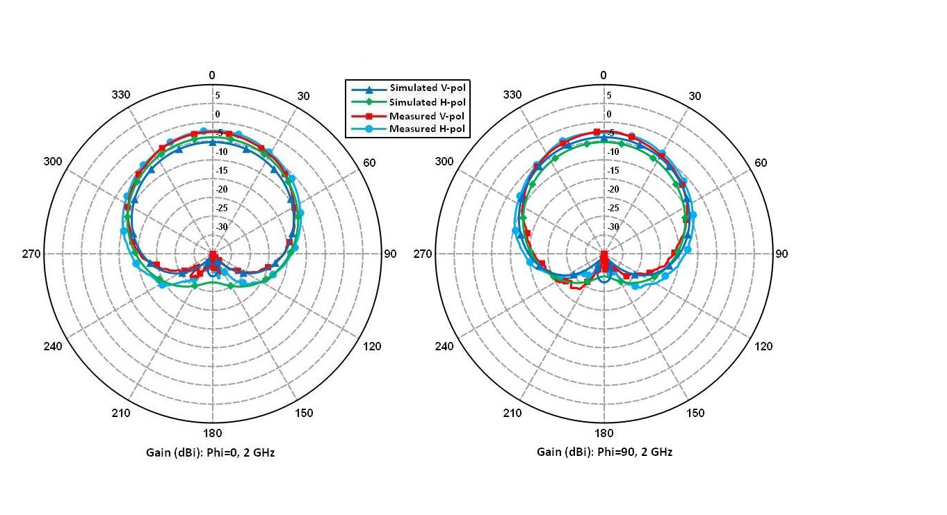 | Figure 6. Measured vs. simulated gain (dBi) for principal planes at 2GHz |
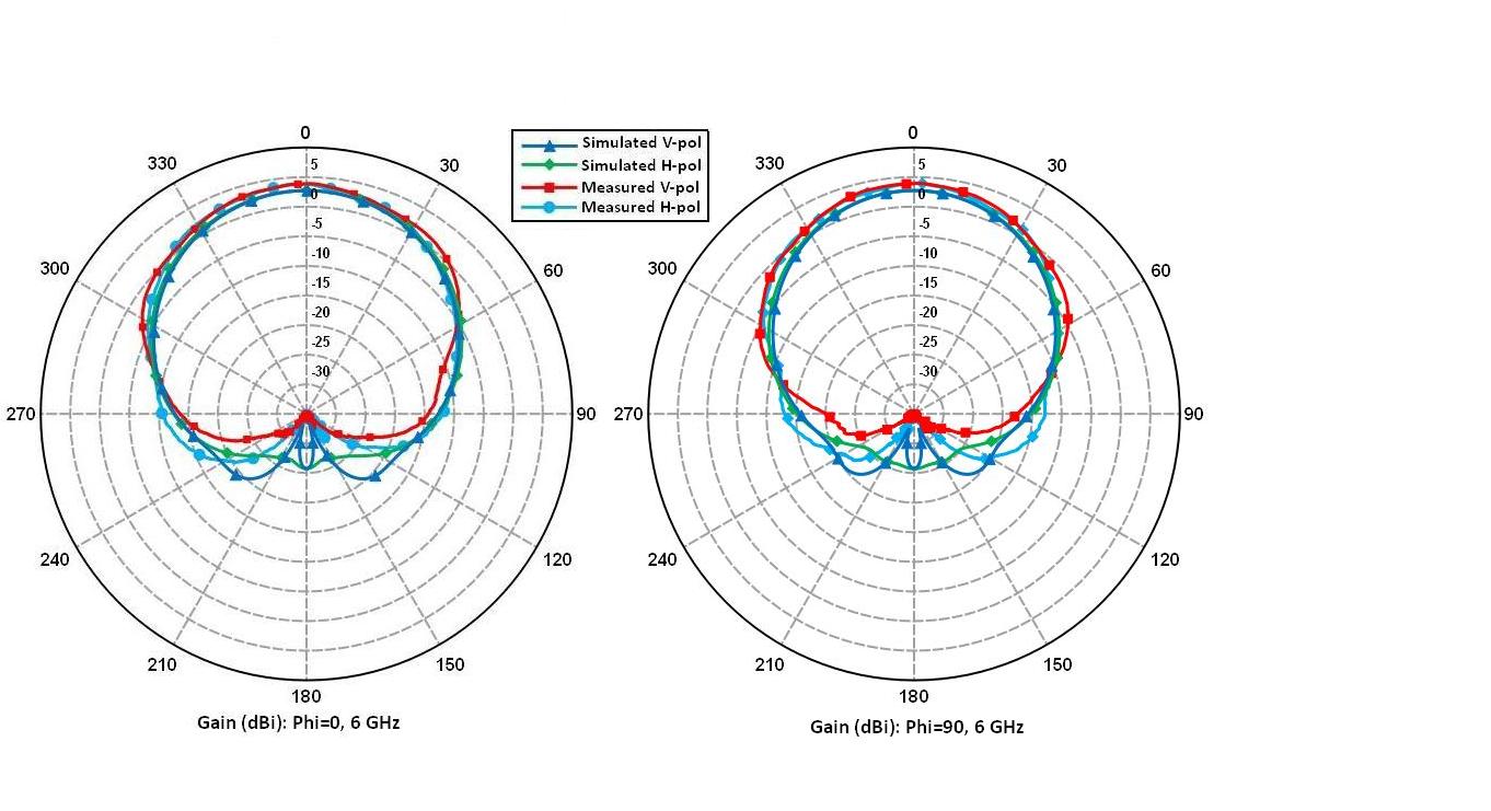 | Figure 7. Measured vs. simulated gain (dBi) for principal planes at 6GHz |
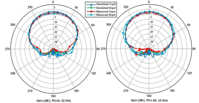 | Figure 8. Measured vs. simulated gain (dBi) for principal planes at 10GHz |
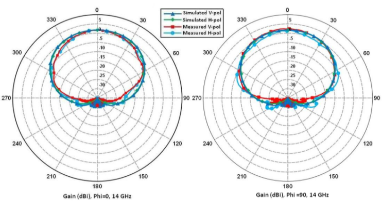 | Figure 9. Measured vs. simulated gain (dBi) for principal planes at 14GHz |
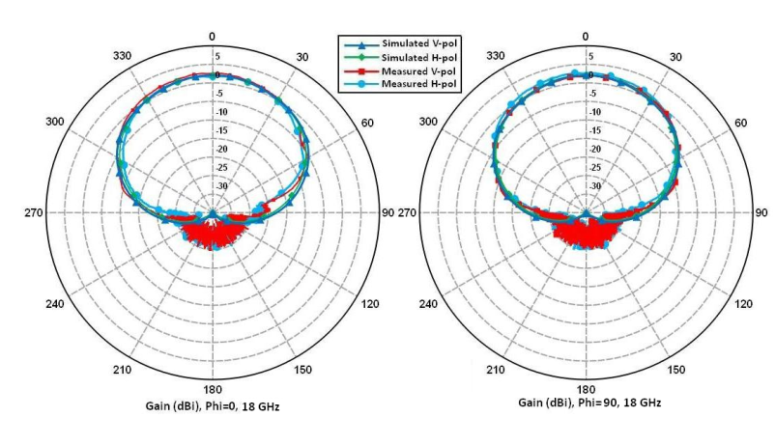 | Figure 10. Measured vs. simulated gain (dBi) for principal planes at 18 GHz |
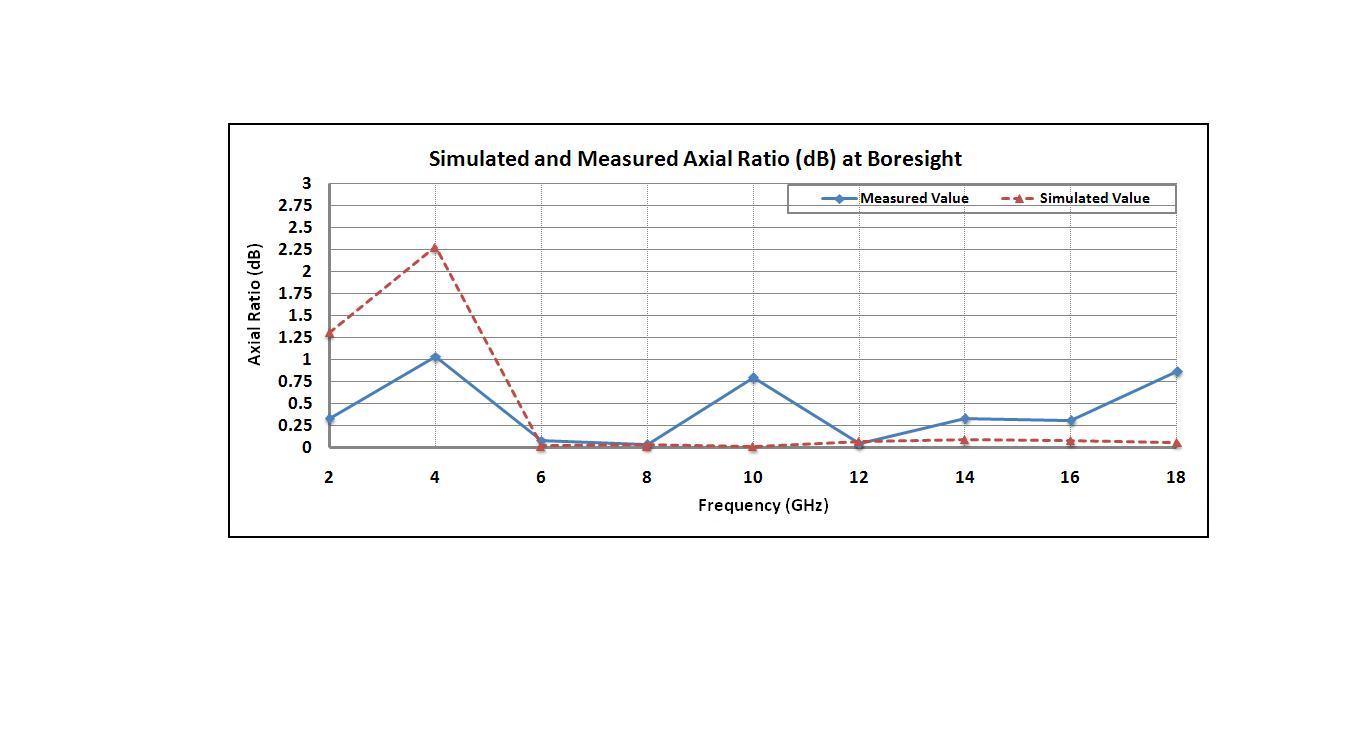 | Figure 11. Axial ratio performance vs. frequency |
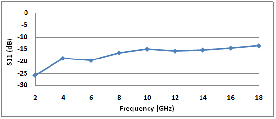 | Figure 12. Return loss S11 (dB) vs. frequency (GHz) |
6. Conclusions
- An effective design procedure for very low-profile, UWB, cavity-backed spiral antennas has been presented. We have approached the problem of designing and optimizing broadband, yet lightweight cavities by using microwave measurement techniques and subsequently applying the genetic algorithm optimization routine to arrive at a geometry that meets desired radiation specifications. The simulated and measurement results show consistent gain and very good axial ratio performance.Using precision measurement techniques for frequency-dependent complex permittivity or permeability values allows us to accurately take advantage of the powerful computational tools that are commercially available for antenna simulation. Our procedure can be successfully extended to the design of any configuration of spiral antenna with a specified cavity depth and UWB gain-bandwidth and axial ratio performance.
ACKNOWLEDGMENTS
- The authors would like to thank Dr. C. J. Reddy at EMSS, USA for academic support with FEKO software.
References
| [1] | J. M. Bell and M. F. Iskander, "A low-profile Archimedean spiral antenna using an EBG ground plane," Antennas and Wireless Propagation Letters, IEEE , vol.3, no.1, pp.223-226, Dec. 2004 |
| [2] | N. Jing, H. Zhao, and Lihao Huang, “A Novel Design of Planar Spiral Antenna with Metamaterial”, PIERS Proceedings, 725 - 728, March 22-26, Xian, China 2010 |
| [3] | H. Nakano, R. Satake, and J. Yamauchi, "Extremely Low-Profile, Single-Arm, Wideband Spiral Antenna Radiating a Circularly Polarized Wave," Antennas and Propagation, IEEE Transactions on , vol.58, no.5, pp.1511-1520, May 2010 |
| [4] | J. Lao, R. H. Jin and J. P. Geng, "UWB Spiral Antenna with Parabolic Reflector," in XXIX URSI General Assembly, Chicago, Illinois, USA. 2008 |
| [5] | L-3 Communications, Randtron Antenna Systems, n.d., “Multi-octave Spiral Antennas”, |
| [6] | http://www.l-3com.com/randtron/f15ant.htm, June, 14, 2011 |
| [7] | Chengdu AINFO Inc., January 12, 2011, “Cavity Backed Spiral Antenna”, http://www.ainfoinc.com/en/p_ant_s_cavs.asp, June 14, 2011 |
| [8] | A. M. Nicolson and G. F. Ross, “Measurement of intrinsic properties of materials by time techniques,” IEEE Transactions on Instrumentation and Measurement, vol. IM-19, pp. 377-382, Nov. 1970 |
| [9] | W. B. Weir, “automatic measurement of complex dielectric constant and permeability at microwave frequencies,” Proceedings of the IEEE, vol. 62, pp. 33-36, Jan. 1974 |
| [10] | J. Baker-Jarvis, E. J. Venzura, and W. A. Kissick, “Improved technique for determining complex permittivity with the transmission/reflection method,” IEEE Transactions Microwave Theory Tech., vol. 38, pp. 1096-1103, Aug. 1990C. J. Kaufman, Rocky Mountain Research Lab., Boulder, CO, private communication, May 1995 |
| [11] | N. N. Al-Moayed, M. N. Afsar, U. A. Khan, S. McCooey, M. Obol, “Nano Ferrites microwave complex permeability and permittivity measurements by T/R technique in waveguide,” IEEE Transactions on Magnetics, vol. 44, no. 7, July. 2008 |
| [12] | M. Obol, “Microwave Technologies – Determination of Magnetic and Dielectric Materials Microwave Properties”, http://arxiv.org/abs/0906.2928 |
| [13] | M. Obol, D. Tilton, and M. N. Afsar, “The Cauchy-Riemann Equations in Determining the Refractive Index of Microwave Isolator of Ferrite-Metal Strips in a Waveguide”, Proceedings of the European Microwave Conference, 2009 European , vol., no., pp.1156-1158, Sept. 29 2009-Oct. 1 2009 |
| [14] | N. Rahman, M. Obol, A.Sharma, and M. Afsar, “Determination of Negative Permeability and Permittivity of Metal Strip Coated Ferrite Disks Using the Transmission and Reflection (TR) Technique”, Journal of Applied Physics, vol.107, no.9, pp.09A513-09A513-3, May 2010 |