Kamila Aliane 1, NasrEddine Benahmed 1, Nadia Benabdallah 2, Yamina Bekri 1, Sidi Mohammed Meriah 1
1University Abou Bekr Belkaid-Tlemcen, P. O. Box 119, (13000) Tlemcen, Algeria
2Preparatory School of Sciences and Technology (EPST-Tlemcen), P. O. Box 165 R.P, (13000) Tlemcen, Algeria
Correspondence to: NasrEddine Benahmed , University Abou Bekr Belkaid-Tlemcen, P. O. Box 119, (13000) Tlemcen, Algeria.
| Email: |  |
Copyright © 2012 Scientific & Academic Publishing. All Rights Reserved.
Abstract
This article presents the electromagnetic parameters (EM) of slotted elliptical tube-lines (SETL) using the method of moments (MoM) in two dimensions. This technique is adapted to study the complex configuration of the line’s system, which does not have a simple analytical solution. The modeling of the SETL structure consists in analyzing the even- and odd-mode characteristic impedances (Z0e, Z0o), the coupling coefficient (k), and the primary inductive and capacitive matrices ([L] and [C]). The EM parameters of the SETL shown into this article are essential for the design of couplers, resonators, and probes among other microwave and wireless components. To demonstrate the SETL in applications, the line’s system was used as a directional coupler and as an MRI probe. The coupler was designed with 10-dB coupling and excellent performance in terms of high directivity and good isolation whereas the MRI probe was designed to operate at 340 MHz (proton imaging at 8 T) and has -66.7 dB minimum reflection and unloaded quality factor (Qo) more than 500 at 328 MHz.
Keywords:
Slotted Elliptical Tube-Lines (SETL), EM Parameters, Mom Calculations, Directional Coupler, MRI Probe, Frequency Response, S-Parameters, High Q
1. Introduction
Slotted elliptical tube transmission lines (SETL) offer some noteworthy characteristics for high-frequency designs, including low signal loss. To evaluate the electromagnetic (EM) parameters of slotted elliptical tube-lines, consider an ideal, lossless, homogenous line’s system formed with a transverse-electromagnetic (TEM) mode. The TEM-mode can be described in terms of its even- and odd-mode impedances (Z0e and Z0o, respectively), the [L] and [C] matrices and the coupling coefficient (k), where [1-3]: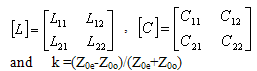 | (1) |
The inductance matrix [L] contains the self-inductances of the SETL on the diagonal, and the mutual inductances between lines in the off-diagonal terms.Matrix [C] accounts for the capacitative effects between the two conductive lines, characterizing the electric field energy storage in the SETL.For this type of multiconductor transmission lines, there are no numerical or experimental EM-results in the scientific literature. The analytical characterization of the EM parameters of the SETL is a difficult task. Numerical methodsare appropriate to solve this problem.In this work, the numerical characterization of the EM parameters of the homogeneous SETL using the method of moments (MoM) is of interest.
2. Slotted Elliptical Tube-Line
Figure 1 offers a cross-sectional view of slotted elliptical tube-lines. The SETL is assumed to be lossless. It has two conductive bands (t) thick, outer shield radius of (rb) and window angle of (θ). A dielectric material with permittivity (εr) fills the inside of the line. The two conductive bands can be mounted on the long (a) or short (b) axes of the ellipse. In this work the conductive bands are fixed on the short axis.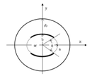 | Figure 1. Cross section of the slotted elliptical tube-lines |
3. Numerical Results
The numerical calculations of the EM parameters of the slotted elliptical tube-lines were carried out with LINPAR for windows (Matrix Parameters for Multiconductor Transmission Lines), a 2D Method of Moments (MoM) software for numerical evaluation of the quasi static matrices for multiconductor transmission lines embedded in piecewise-homogeneous dielectrics [4]. The technique used in the program is based on an electrostatic analysis. In this analysis the dielectrics are replaced by bound charges in a vacuum, and the conducting bodies are replaced by free charges. A set of integral equations is derived for the charge distribution from the boundary conditions for the electrostatic potential and the normal component of the electric field. The method of moments is applied to these equations, with a piecewise-constant (pulse) approximation for the total charge density and the Galerkin technique. LINPAR for windows can analyze arbitrary planar transmission lines and can also analyze any other structure defined by the user.For the homogeneous SETL, we were obliged to supply the cross section of the structure and all relevant dielectric characteristic including the segmentation by using our programs in FORTRAN.In order to find the EM parameters of the shielded SETL, we were interested in the analysis of the structure presented in figure 1 having the following features: a=1.8×b and t=0.1×b.We applied the MoM-based numerical tool to the analysis of the shielded SETL with a segmentation of the charged surfaces of the structure shown in figure 2, for different values of the outer radius-to-long axis ratio (rb/a). The MoM approach makes it possible to simulate the performance of a design and decides if a given set of constraints makes it possible to realize the desired microwave component.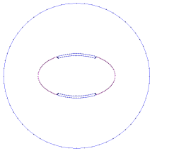 | Figure 2. Segmentation of the charged surfaces of the the slotted elliptical tube-lines |
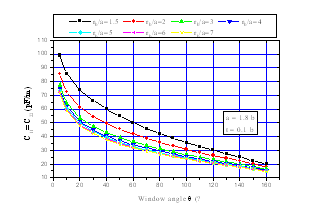
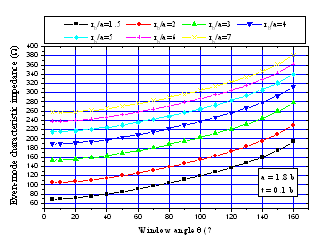 | Figure 3. Effects of the window angle (θ) on the even-mode characteristic impedance (Z0e) for different values of the outer radius-to-long axis ratio (rb/a), where εr=1 |
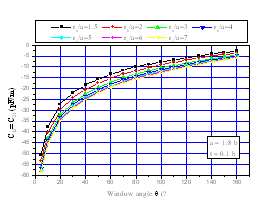
The numerical results for the characteristic impedances of the shielded slotted elliptical tube-lines using the MoM method are shown in figures 3 and 4. 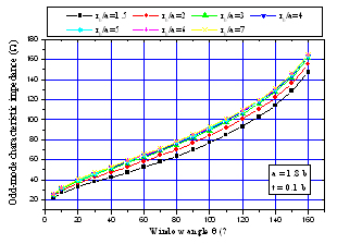 | Figure 4. Effects of the window angle (θ) on the odd-mode characteristic impedance (Z0o) for different values of the outer radius-to-long axis ratio (rb/a), where εr=1 |
Figure 5 shows the influence of the window angle (θ) of the shielded SETL on the coupling coefficient (k) for different values of the outer radius-to-long axis ratio (rb/a).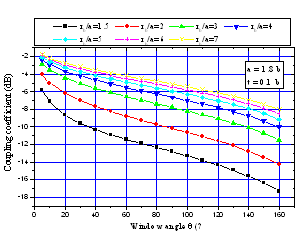 | Figure 5. Effects of the window angle (θ) on the coupling coefficient for different values of the outer radius-to-long axis ratio (rb/a) |
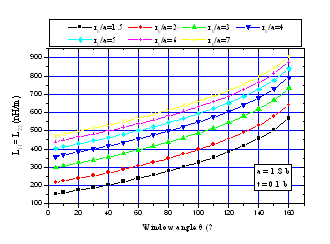 | Figure 6. Effects of the window angle (θ) on the elements (L11, L22) of the inductance matrix [L] for different values of the outer radius-to-long axis ratio (rb/a) |
The MoM analysis approach was also used to determine the effects of the window angle on the primary inductive and capacitive matrices ([L] and [C]) for the shielded SETL, with results shown in figures 6 to 9.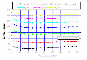 | Figure 7. Effects of the window angle (θ) on the elements (L12, L21) of the inductance matrix [L] for different values of the outer radius-to-long axis ratio (rb/a) |
 | Figure 8. Effects of the window angle (θ) on the elements (C11, C22) of the capacitance matrix [C] for different values of the outer radius-to-long axis ratio (rb/a), where εr=1. |
 | Figure 9. Effects of the window angle (θ) on the elements (C12, C21) of the capacitance matrix [C] for different values of the outer radius-to-long axis ratio (rb/a), where εr=1 |
The EM parameters-results of the SETL shown into this article are essential for the design of couplers, resonators, and probes among other microwave and wireless components.To demonstrate the SETL in applications, the line’s system was used as a directional coupler and as an MRI probe. Here the scattering parameters ([S] matrix) of the two designed circuits were found using an adapted numerical model [5]. The coupler was designed with 10-dB coupling and excellent performance in terms of high directivity and good isolation whereas the MRI probe was designed to operate at 340 MHz (proton imaging at 8 T) and has -66.7 dB at 328 MHz minimum reflection and unloaded quality factor (Qo) more than 500 at 328 MHz.
4. Design of a Directional Coupler
Figure 10 presents the structure of a directional coupler using the shielded slotted elliptical tube-lines. The fixed parameters of the coupler include a characteristic impedance of 50 ohms, desired coupling coefficient between the two lines of 10 dB, and an operating frequency of 2 GHz. The features of the coupling line obtained from the figures above include a dielectric constant of 4.7, a long-to-short axis ratio (a/b) of 1.8, a band thickness-to-short axis ratio (t/b) of 0.1, an outer radius-to-long axis ratio (rb/a), of 2, a window angle of 88 deg., a coupler length of 17.3 mm, even- and odd-mode characteristic impedances, Z0e and Z0o, respectively, of 66.85 and 34.9 ohms. The inductance matrix appears as 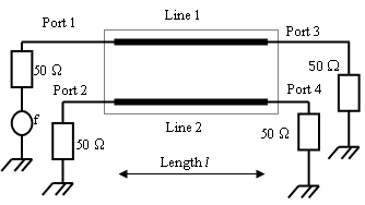 | Figure 10. Schematic circuit of the coupler using SETL |
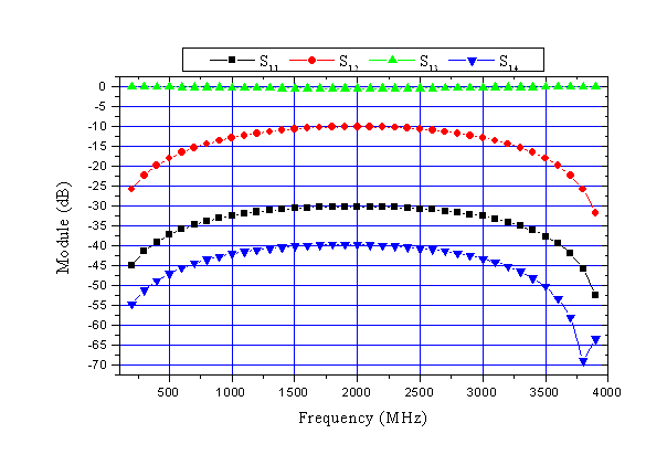 | Figure 11. Scattering parameters for the designed coupler as function of frequency |
For the designed directional coupler using SETL, figure 11 shows that in the frequency range of 1.5 to 2.5 GHz, coupling is 10 dB, isolation is 40 dB and directivity is 30 dB.These results show clearly the desired coupling at the operating frequency (10 dB at 2 GHz) and excellent performance in terms of high directivity (30 dB) and good isolation (40 dB).
5. Design of an MRI Probe
Slotted elliptical tube-coil [6-8] is well suited for clinical applications (e.g. wrist or abdomen) but is also appropriate for non-medical samples (e.g. packaged foods).From the EM parameters-results presented in this article, it is possible to estimate the resonance spectrum (S11) of the MRI probe using the shielded slotted elliptical tube-lines shown in figure 12.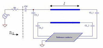 | Figure 12. Schematic circuit of the MRI probe using the shielded SETL |
The MRI probe developed for this article consists of the shielded SETL with length l, matching capacitor CM, and terminating capacitors CSi and CLi (i = 1, 2).The unloaded quality factor (Qo) of the MRI probe can be estimated from the reflection-parameter (S11) sweep with frequency [3]:where fr = the resonance frequency of the circuit, fu = 3-dB frequency above the resonance frequency, and fl = the 3-dB frequency below the resonance frequency.For rb/a=2.4 and θ=72°, the EM parameters of the shielded SER coil are:Finally, the MRI probe shown in figure 12 was designed with the following features:- a short axis (b) of 10 cm;- a long-to-short axis ratio (a/b) of 1.8;- an outer radius-to-long axis ratio (rb/a) of 2.4;- a sheet thickness-to-short axis ratio (t/b) of 0.1;- a window angle (θ) of 72°; - a dielectric constant (εr) of 1;- a resonator length ( l ) of 22cm;- a matching capacitor (CM) with value of 20 pF; and source and load terminating capacitors,(CSi) and (CLi), respectively, both with value of 1 pF.The simulated frequency response of (S11) at the RF port of the MRI probe using the shielded slotted elliptical tube-lines is shown on figure 13.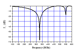 | Figure 13. Frequency response of designed MRI probe using the shielded SETL |
This curve presents a minimum around the chosen resonant frequency i.e. 340 MHz. The obtained minimum of reflection for MRI probe using the shielded SETL is very low at the resonance frequency (-66.7 dB at 328 MHz). Using the relation (2), the unload quality factor Qo is superior than 500.
6. Conclusions
This article has presented the design of a directional coupler and an MRI probe using shielded slotted elliptical tube lines. To reach this objective, it was necessary to determine the electromagnetic parameters of the shielded SETL. In the 0.1 to 4 GHz frequency band, the numerical calculations were carried out with LINPAR for windows using the method of moments (MoM) which allows us the determination of the quasi static matrices ([L] and [C]), the even- and odd-mode impedances (Z0e and Z0o, respectively) and the coupling coefficient for the SETL.The designed directional coupler with 10-dB coupling using shielded slotted elliptical tube lines shows excellent performance in terms of high directivity and good isolation, whereas the MRI probe was designed to operate at 340 MHz (proton imaging at 8 T) and has -66.7 dB at 328 MHz minimum reflection and unloaded quality factor (Qo) more than 500 at 328 MHz.All the curves presented in this work, taking into account the influence of the electrical and geometrical parameters prove the interest of the 2D Method of Moments software and are essential for the design of couplers, resonators, and probes among other microwave and wireless components. The association of analytical functions to these curves remains possible.
References
| [1] | N. Benabdallah, N. Ben Ahmed F. T. Bendimerad and B. Benyoucef, “MoM analysis and design of a compact coaxial-to-microstrip directional coupler,” Wireless engineering and technology (WET), vol. 2, no 2, pp.45-52, April 2011. |
| [2] | N. Benabdallah, N. Ben Ahmed F. T. Bendimerad and B. Benyoucef, “Micromachined microstrip forms bandstop filters», Microwaves and RF, vol. 49, no 13, pp. 75-79, December 2010. |
| [3] | R. Bouhmidi, N. Benabdallah, N. Ben Ahmed and M’. khelif,” Design coupled microstrip resonators for MRI,” Microwaves and RF, vol. 46, no 3, pp. 59-66, March 2007. |
| [4] | A.R. Djordjevic, D. Darco, M.C. Goran and T. Sarkan, Circuit analysis models for multiconductors transmission lines, Artech Housse, 1997. |
| [5] | A.R. Djordjevic, M. Bazdar, G. Vitosevic, T. Sarkar, and R.F. Harrington, Scattering parameters of microwave networks with multiconductor transmission lines, Artech House, Norwood, MA, 1990. |
| [6] | S. Crozier, L. K. Forbes, W. U. Roffmann, K. Luescher D. M. Doddrell, “A methodology for current density calculations in high-frequency RF resonators,” Concepts Magn. Reson., vol. 9, pp. 195-210, 1997. |
| [7] | M. C. Leifer, “Theory of the quadrature elliptic birdcage coil,” Magn. Reson. Med, vol. 38, pp. 726-732, 1997 |
| [8] | S. Bobrof, M. J. McCarth, “Variations on the slotted-tube resonator: Rectangular and elliptical coils,” Magn. Reson. Imaging, vol. 17, pp. 783-789, 1999. |
 Abstract
 Reference
 Full-Text PDF
 Full-Text HTML