Prasun Banerjee 1, Gautam Ghosh 2, Salil Kumar Biswas 1
1Department of Physics, University College of Science and Technology, University of Calcutta, Kolkata, India
2Institute of Radio Physics and Electronics, University College of Science and Technology, University of Calcutta, Kolkata, India
Correspondence to: Prasun Banerjee , Department of Physics, University College of Science and Technology, University of Calcutta, Kolkata, India.
| Email: |  |
Copyright © 2012 Scientific & Academic Publishing. All Rights Reserved.
Abstract
An analytical solution for the measurement of dielectric constant of relatively small-sized medium loss samples is formulated in TE011 resonant mode rectangular cavity. Next a simple but ingenious technique based on cavity perturbation techniques in X-band frequencies is presented. The technique is established by using materials having known dielectric constants like p-type silicon. Finally, the technique was applied to study the dielectric constant of wax as a monomer and Ethylene Vinyl Acetate (EVA) as a polymer with carbon loading.
Keywords:
Dielectric Constant, Microwave Frequencies, X-Band, Cavity perturbation Method
Cite this paper: Prasun Banerjee , Gautam Ghosh , Salil Kumar Biswas , A Simple Method to Determine the Dielectric Constant of Small-Sized Medium-Loss Samples at X-Band Frequencies, International Journal of Electromagnetics and Applications, Vol. 1 No. 1, 2011, pp. 12-15. doi: 10.5923/j.ijea.20110101.03.
1. Introduction
The permittivity of a material is an important parameter in microwave applications because of its relation with processing parameters such as temperature and frequency of the alternating electromagnetic field. The real part of permittivity (ε') is associated with the ability of a dielectric material to store or couple electromagnetic energy in it. A high εr is desirable for circuit miniaturization, because the size of a microwave component is inversely proportional to the square root of its dielectric constant.When microwaves enter a dielectric material they are slowed down by a factor equal to the square root of the dielectric constant, which implies that the wavelength decreases by the same amount (the frequency is unaffected). Mathematically, this means that  , where λd is the wavelength in the dielectric and λ0 is the wavelength in vacuum. At microwave frequencies the dielectric characteristics of para-electric ionic crystals are determined by the superposition of ionic and electronic polarization mechanisms. However, since the ionic component of polarization is predominant up to infrared frequencies of ≈ 10 THz, it is the ionic dipoles which contributing mostly towards the dielectric properties.Although many effective characterization methods have been developed, there is an ongoing effort to create newer, better techniques that produce results with higher precision and better accuracy[1].Even though different approaches have been devised to electrically characterize material properties, they all rely on the same underlying principles. Basically the sample is subjected to a known electromagnetic field to determine the change in phase and amplitude of the field from which the electrical properties of a sample can be determined. Among the various methods employed at microwave frequencies, measurement techniques based on cavity-perturbation are the most accurate[2]. In this method the dielectric constant and loss factor of the material were determined by inserting a small, appropriately shaped sample into the cavity and observing the shift in resonant frequency and the change in the Q-factor[3-5]. In the cavity perturbation method small holes can be drilled in the cavity walls and the sample can be inserted into the sample holder. By using this technique the cavity need not be taken apart for placing the sample and errors due to misalignment of the cavity may be avoided[6].Large samples are difficult to obtain at times. Further, the transmission loss for such samples may be quite high making the signal to low for accurate measurements. These difficulties are avoided in the technique, described here, which requires a small sample to be placed against one of the narrow walls of a rectangular cavity where the electric field and, therefore, the perturbation is also minimum.
2. Theory
When a cavity having length c, breadth a and width b is excited by an electromagnetic wave then the electric and magnetic energy stored inside the cavity can be expressed by the equation | (1) |
 | (2) |
At resonance WE=WM .The electric field of the resonant electromagnetic wave in the TE011 mode can be expressed as[7] | (3) |
For the empty cavity  | (4) |
When the sample is inserted, energy stored by the sample can be expressed as | (5) |
Case I: RECTANGULAR SHAPED SAMPLEWhen a rectangular shaped sample of width W, breadth B and thickness d is inserted inside the cavity through which electromagnetic energy is flowing, some energy is stored inside the sample due to its capacitive effect. Assuming that for small samples (dimensions small compared to that of the cavity) the change in the electric field is negligible the stored energy can be expressed as  | (6) |
When W<< c, d<< a, the energy stored in the cavity can be expressed as  | (7) |
Since the stored magnetic energy remains the same, we can writeWE=WS+WC.Hence using equation (4) and (7) we have | (8) |
 | (9) |
where εr=εS/ε0.Hence for a rectangular sample we can determine the dielectric constant of the material by knowing the frequency shift occurring due to the insertion of the material sample inside the cavity.Case II: CYLINDRICALLY SHAPED SAMPLEWhen a cylindrically shaped sample having radius r and thickness d is inserted inside the cavity then the energy stored inside the sample can be expressed as | (10) |
The energy stored in the cavity is | (11) |
But, according to the conservation of energy  | (12) |
where ω and ω0 are respectively the resonant frequencies of the cavity with and without the sample.
3. Experimental Results
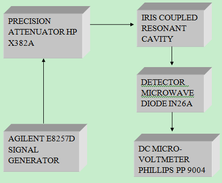
Materials, like p-type silicon, whose dielectric constants are well known were used to standardize the technique. Three rectangular X-band cavities having lengths 27.5mm, 21.8mm and 18.3mm fabricated to resonate respectively at 8.51, 9.46 and 10.47 GHz were used for the measurement of the dielectric constant. Small irises (2.5mm) at either end of the cavity coupled the power into and out of it. The frequency was kept stable by using an Agilent E8257D signal generator. The cavity was connected to a sensitive DC micro-voltmeter Philips PP9004 for the detection of shift in the resonant frequency (Figure. 1). At resonance, maximum transmission of the signal occurs so that the frequency at which maximum deflection on the micro-voltmeter is observed gives the resonant frequency. The sample was placed on one of the narrow faces of the cavity such that it caused minimum perturbation of the electric field. Rectangular sample of p-type silicon having w =4.0mm, b = 4.0mm and of different thickness increasing from 2.5mm to 6.0mm in steps of 0.5mm were inserted in the cavity and the resulting change in the resonant frequency was observed.  | Figure 1. Experimental set-up for the measurement of dielectric constant |
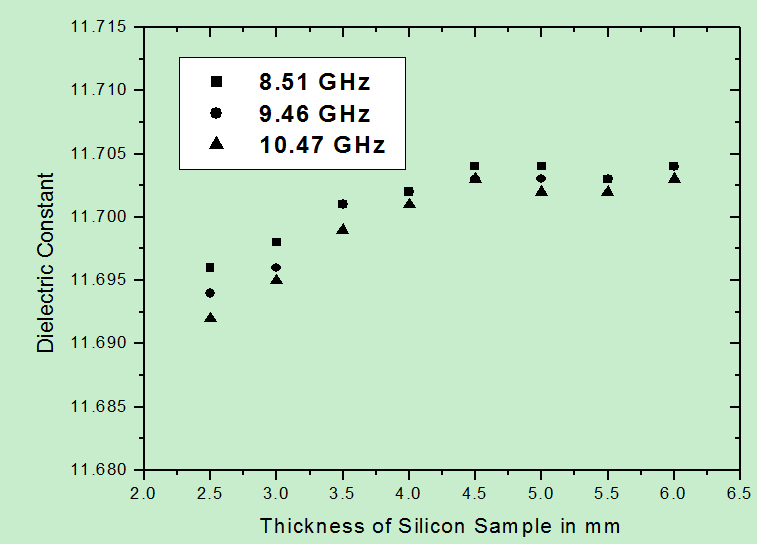
 | Figure 2. Variation of measured dielectric constant of rectangular-shaped samples of p-type silicon as a function of sample thickness at frequencies 8.51 GHz, 9.46 GHz, 10.47 GHz |
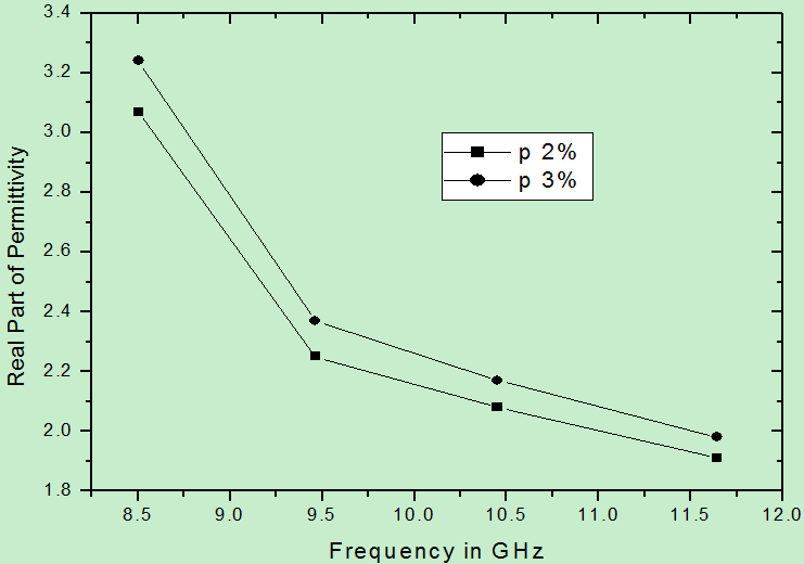
The variation of dielectric constant with sample thickness for three measured frequencies is shown in Figure. 2. It is observed that for p-type silicon the dielectric constant increased with increasing thickness of the sample up to 4.0mm. For thickness greater than 4.0 mm it remained constant at a value of about 11.703. The values of dielectric constant obtained for both Perspex and Teflon are in good agreement with those given by Dube and Verma[8].Figure 3 shows the variation of the real part of the permittivity (using (12)) with frequency for the two different cylindrically shaped conducting wax samples having their DC resistance of the order of a few hundred kΩ. These samples have their nominal percolation (p) values close to percolation threshold (pc). | Figure 3. Real part of permittivity with the variation of frequency for wax with 2% and 3% carbon |
This result is in direct agreement with Kramers-Kronig relations[9] according to which dielectric constant in the microwave bands is almost always a monotonically decreasing function of increasing frequency (Figure 3). The permittivity of medium-loss materials decreases slowly (dispersion) with frequency than that of high-loss materials. In the radio frequency and low microwave frequency bands, an increase in the measured dielectric constant with frequency is almost always due to fixture-geometrical resonances or other fixture-dependent artifacts.The maximum error  also increases with increasing conductivity and were 10% and 11% respectively for 2% and 3% of carbon. Similar measurements were also carried out on other systems like carbon-polymers for further insight into the microwave properties of such binary mixtures. Measurement was done for EVA rubber having 40 volume of carbon with variation of thickness of the sample. The carbon used is Vulcan XC-72 type.
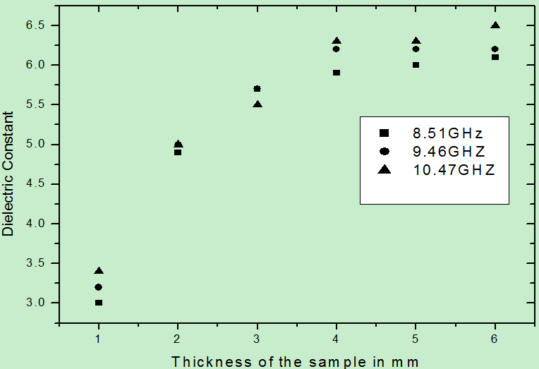
  | Figure 4. Dielectric constant vs. thickness of cylindrically shaped samples of EVA.40V at 8.51, 9.46 and 10.47 GHz (‘V’ represents Vulcan XC-72) |
Similar trends were observed for the value of EVA rubber composites giving a value of 6.20 for dielectric constant at a frequency 9.46 GHz. The lower value of dielectric constant obtained for the sample thickness less than 4mm is due to the fact that smaller samples produced very small perturbation of the electric field resulting in negligible stored energy inside the sample. (WS) and equation (1) does not hold good in that region of sample thickness. However, the values obtained for larger thickness agree with values reported in literature[10].
4. Discussion and Conclusions
The methods discussed here for the determination of the dielectric constant in the high frequency region is applicable for high Q samples i.e. medium loss materials only. To avoid retuning of the cavity the sample dimensions are selected such that on introduction of the sample inside the cavity the change in resonant frequency is not more than 5%. Utmost care has been taken to maintain the same coupling condition with the external circuit before and after the introduction of the sample. The absolute experimental error in the measurement of the microwave conductivity is about 0.5% owing to uncertainties in the geometrical dimensions of the sample, reproducibility errors in positioning the sample inside the cavity and meter tracking errors in the dc micro voltmeter. This method will seemingly work best for thin materials with thickness between 4-6 mm ranges. As the thickness of the material increases, the radiation and standing waves caused by the metallic discontinuity have been shown to cause a substantial increase in the magnitude and randomness of the systematic error. The increasing systematic error can cause the accuracy of the solution to decrease to unacceptable levels. Hence we have investigated the dielectric behavior of the sample up to 6 mm of sample thickness only. Further investigations are required to determine precisely the dependence of the error upon thickness of the sample more than 6 mm. It may be noted that placing the samples on the broad wall of the cavity would increase the sensitivity of the measurement but at the same time lossy samples would cause a large distortion of the electric field.
References
| [1] | Agilent, Basics of Measuring the Dielectric Properties of Materials. 2005, Agilent Technologies, Inc.: U.S.A. p. 1-32 |
| [2] | J.Baker-Jarvis, M.D.Janezic, J.H.Grovenor Jr., And R.G.Geyer, “Transmission/reflection and short-circuit line methods for measuring permittivity and permeability, ”NIST Tech. Note 1355(revised), Dec. 1993 |
| [3] | A.W.Kraszewski And S.O.Nelson, “Observations on resonant cavity perturbation by dielectric objects,”IEEE Trans. Microwave Theory Tech., vol.40, pp.151–155, Jan.1992 |
| [4] | S.B. Balmus, G.-N. Pascariu, F. Creanga, I. Dumitru, D. D. Sandu, “The cavity perturbation method for the measurement of the relative dielectric permittivity in the microwave range”, Journal Of Optoelectronics And Advanced Materials, Vol. 8, No. 3, June 2006, p. 971 – 977 |
| [5] | P. Banerjee, G. Ghosh and S. K. Biswas, ‘ Journal of Optoelectronics and Advanced Materials, vol.12, no.6, June 2010, pp. 1367-71 |
| [6] | Kumar And S. Sharma, Measurement Of Dielectric Constant And Loss Factor Of The Dielectric Material At Microwave Frequencies, Progress In Electromagnetic Research, Pier 69, 47–54, 2007 |
| [7] | Hyper and ultrahigh frequency engineering, Robert Irving Sarbacher, William Alden Edson, J. Wiley & Sons, inc., 1943 |
| [8] | D. C. Dube, M. T. Lanagan, J. H. Kim, and S. J. Jang, “Dielectric measurements on substrate materials at microwave frequencies using a cavity perturbation technique,” J. Appl. Phys., vol. 63, pp. 2466–2468, Apr. 1988 |
| [9] | Papoulis, A. The Fourier Integral and Its Applications. New York: McGraw-Hill; 1987 |
| [10] | P. Banerjee, S. K. Biswas and G. Ghosh; ‘Dielectric Properties of EVA Rubber Composites at Microwave Frequencies – Theory, Instrumentation and Measurements’; Journal of Microwave Power and Electromagnetic Energy (JMPEE) , 45(1), pp 24-29, 2011 |

 , where λd is the wavelength in the dielectric and λ0 is the wavelength in vacuum. At microwave frequencies the dielectric characteristics of para-electric ionic crystals are determined by the superposition of ionic and electronic polarization mechanisms. However, since the ionic component of polarization is predominant up to infrared frequencies of ≈ 10 THz, it is the ionic dipoles which contributing mostly towards the dielectric properties.Although many effective characterization methods have been developed, there is an ongoing effort to create newer, better techniques that produce results with higher precision and better accuracy[1].Even though different approaches have been devised to electrically characterize material properties, they all rely on the same underlying principles. Basically the sample is subjected to a known electromagnetic field to determine the change in phase and amplitude of the field from which the electrical properties of a sample can be determined. Among the various methods employed at microwave frequencies, measurement techniques based on cavity-perturbation are the most accurate[2]. In this method the dielectric constant and loss factor of the material were determined by inserting a small, appropriately shaped sample into the cavity and observing the shift in resonant frequency and the change in the Q-factor[3-5]. In the cavity perturbation method small holes can be drilled in the cavity walls and the sample can be inserted into the sample holder. By using this technique the cavity need not be taken apart for placing the sample and errors due to misalignment of the cavity may be avoided[6].Large samples are difficult to obtain at times. Further, the transmission loss for such samples may be quite high making the signal to low for accurate measurements. These difficulties are avoided in the technique, described here, which requires a small sample to be placed against one of the narrow walls of a rectangular cavity where the electric field and, therefore, the perturbation is also minimum.


 also increases with increasing conductivity and were 10% and 11% respectively for 2% and 3% of carbon. Similar measurements were also carried out on other systems like carbon-polymers for further insight into the microwave properties of such binary mixtures. Measurement was done for EVA rubber having 40 volume of carbon with variation of thickness of the sample. The carbon used is Vulcan XC-72 type.
 Abstract
 Reference
 Full-Text PDF
 Full-text HTML