B. Mihailescu 1, I. Plotog 1, P. Svasta 1, M. Vladescu 2
1Centre for Technological Electronics and Interconnection Techniques, “Politehnica” University of Bucharest, Bucharest, 060042, Romania
2Elsix, Bucharest, Romania
Correspondence to: B. Mihailescu , Centre for Technological Electronics and Interconnection Techniques, “Politehnica” University of Bucharest, Bucharest, 060042, Romania.
| Email: |  |
Copyright © 2012 Scientific & Academic Publishing. All Rights Reserved.
Abstract
The paper is the result of studies, experiments and simulations regarding electromagnetic compatibility (EMC) performance of an intelligent electronic module used to obtain variable and controllable power injection during the Vapour Phase Soldering process (VPS) including the power-on and power-off phases. The module represents an original solution for low conducted and especially low radiated emissions by switching the power semiconductor devices close to the zero crossing of the mains voltage. The necessity to be optimized from EMC points of view is resolved by modelling and simulating using 3D EM simulation software, REMCOM XFdtd, for evaluating the performance and electromagnetic field effects of the VPS process power control module considered as a radiating device. The modelling process is based on preliminary measurements already taken and validated by other complex measurements which imply the need for the new experiments design. The authors intend to develop a design methodology based on the works presented in the paper which will include modelling and EM simulation, in order to complete the design for excellence (DFX) activities in case of the new products development processes.
Keywords:
Electromagnetic Compatibility, Vapour Phase Soldering, EM Simulation, DFX Methodology
Cite this paper: B. Mihailescu , I. Plotog , P. Svasta , M. Vladescu , The Modeling & EM Simulation Assessment as Part of DFX Methodology, International Journal of Electromagnetics and Applications, Vol. 1 No. 1, 2011, pp. 7-11. doi: 10.5923/j.ijea.20110101.02.
1. Introduction
According with DFX criteria, the electronic module must comply with EMC requirements detailed in correspondence with functional work conditions of the module. In our case, the module is used for power control in VPS process, being a part of a complex VPS machine and multifunctional controlling equipment. In consequence, the power control module must have especially, very low levels of radiated emissions. The activities were scheduled in three steps: experiments for defining entry data (Figure 1), modelling& simulation and validation by experiments. The process control module presented in Figure 1 was developed as a low cost, energy efficient prototype which is based on a solid-state relay (SSR) as the switching element (power switch block), offering an isolated interface between the high voltage AC input and the low voltage DC control circuitry. An important feature of the SSR named above is zero cross detection capability which relates to low conducted disturbances and very low radiated emissions. The capability has been designed through software in the microcontroller of the process control module and is supported also by the solid state relay. The SSR has been designed to switch the current to the load only if it receives the switching command from the microcontroller when there has been detected a zero crossing of the mains voltage.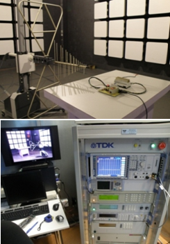 | Figure 1. EMC experiments in semi-anechoic chamber |
2. Electromagnetic Compatibility Tests
In the first step the tests, according to CISPR 22[1], were made in a 3m semi-anechoic chamber using a Line Impedance Stabilization Network (LISN), an EMI Test Receiver, calibrated RF cables and antennas. The EMC experiments were made with a resistive load of 2.2kW. The recorded perturbations levels for both conducted and radiated emissions tests were then compared to the limits from Table 1 where the electronic module was classified as a class B Information Technology Equipment.| Table 1. Limits of conducted disturbances |
| | FREQUENCY (MHz) | CISPR22 LIMITS[dBμV] quasipeak | | 0.15 … 0.5 | 66 to 56 | EUT Class B | | 0.5 … 5MHz | 56 | | 5 … 30MHz | 60 | | Conducted Disturbances (CISPR22, cap. 6 [1])EN 55022[4]) |
|
|
| Table 2. Radiated emissions at a measuring distance of 3 meters |
| | FREQUENCY (MHz) | CISPR22 LIMITS [dB(μV/m)] quasipeak | | 30 … 230MHz | 40 | EUT Class B | | 230 … 1000MHz | 47 | | 30 … 230MHz | 50 | EUT Class A | | 230 … 1000MHz | 57 | | Radiated Emissions (CISPR22 [1]) |
|
|
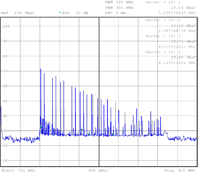 | Figure 2. Conducted disturbances of VPS electronic module |
The radiated emissions tests were made according to Figure 1, where the horizontal polarized antenna was placed at 3, 2 and 1 meters distance away from the EUT in order to record the maximum level of perturbations and its specific test configuration.Because the tested equipment is not a radiofrequency device, which would continuously emit, it was not possible to go through the standard test procedure as described in CISPR 22[1]. Therefore, the EUT was placed on the 0.8 meters height non-conductive table in front of the log-periodic antenna, and we measured the radiated emissions corresponding to the equipment operating mode. The turn-table and the antenna mast were manually controlled in order to record the maximum radiated emissions level.| Table 3. Quasi-peak levels of conducted perturbations |
| | PEAK | FREQ. (MHz) | LEVEL [dB(μV)] | LIMITS (CISPR 22) | | PEAK 1 | 2.02 | 70.75 | 56 dB(μV) | | PEAK 2 | 4.25 | 93.80 | 56 dB(μV) | | PEAK 3 | 4.61 | 78.14 | 56 dB(μV) | | PEAK 4 | 8.33 | 39.69 | 60 dB(μV) | | frequency band from 150 kHz to 9.5MHz(load = 2.2kW) |
|
|
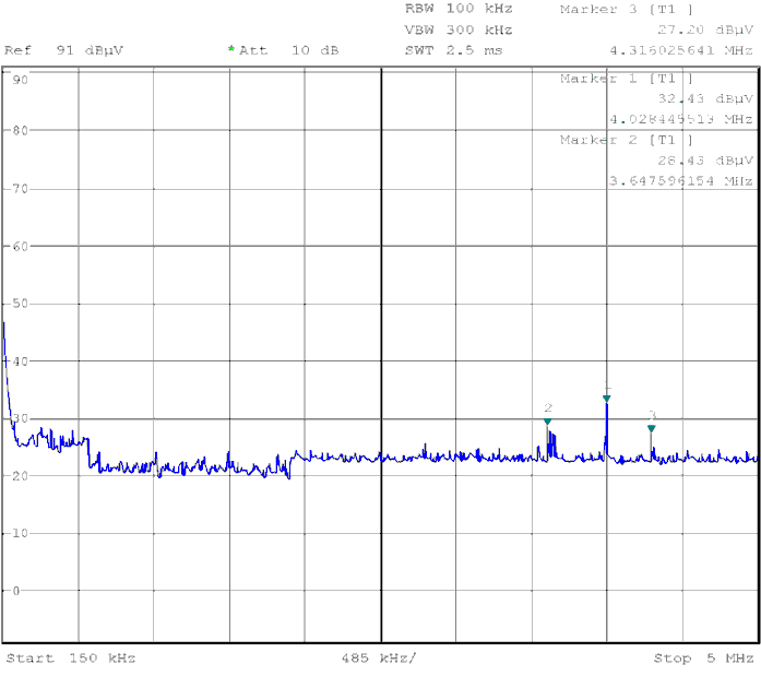 | Figure 3. Conducted disturbances of VPS electronic module |
In Table 3 is shown the highest quasi-peak levels recorded in laboratory throughout the tested frequency band at the shortest distance of 1 meter from the module. At the standard distance of 3 meters from the antenna, the module showed lower levels of radiated emissions. Following the CISPR 22 specifications for testing the electromagnetic radiations the recorded emissions were well above the limits imposed by the standard for category B of the equipment under test (EUT).| Table 3. Quasi-peak levels of radiated emissions |
| | PEAK | FREQ. (MHz) | LEVEL[dB(μV)/] | LIMITS (CISPR 22) | | PEAK 1 | 4.02 | 32.43 | 40 dB(μV)/m | | PEAK 2 | 3.64 | 28.43 | 40 dB(μV)/m | | PEAK 3 | 4.31 | 27.20 | 40 dB(μV)/m | | frequency band from 150 kHz to 9.5MHz(load = 2.2kW) |
|
|
3. Electromagnetic Modeling and Simulation
In order to be able to run the simulation, the 3D CAD design of the module has been imported into XFdtd (Figure 4). There are two magnetic components, a main transformer and a coil with magnetic core, shown with blue color inside the module enclosure. These components and the solid-state relay have been considered to be the sources of electromagnetic emissions. There is also the command of the SSR received from the microcontroller, but because the value of the current is approximately 10mA the electromagnetic radiation is insignificant and has not been taken into consideration. The current the SSR is capable of switching towards the output has been defined as 5A during start-up and 10A during normal operation. A maximum of 16A have been introduced in simulation.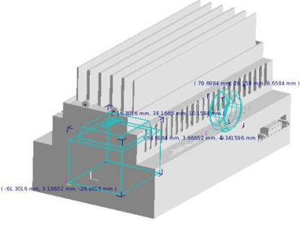 | Figure 4. View of the 3D CAD design imported into XFdtd |
The ferromagnetic materials of the magnetic toroidal core have been set up as well as those for the other sources of electromagnetic emissions. We have run various meshing algorithms (fast and adaptive, with automatic and manual control of the mesh parameters). For example a 2D meshing system XY-YZ-ZX is shown in Figure 5. Comparing the laboratory measurements and simulations results the authors was able to validate the meshing algorithm.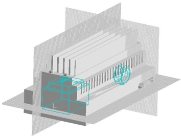 | Figure 5. 2D meshing system XY-YZ-ZX |
4. Results of EM Simulations & Tests
The emission levels recorded for conducted disturbances at the mains port exceed the CISPR 22 limits, while the radiated emissions were almost non-existent (Figure. 2). The measurements emphasize the importance of the differential filter present in the supply block of the module. In the second step, the authors used 3D EM simulation software, namely REMCOM XFdtd, in order to simulate the module and compare the results with the measurements made in the laboratory. Seen in Figure 6 and 7 are the 3D geometry results of the modeled CAD design of the electronic device.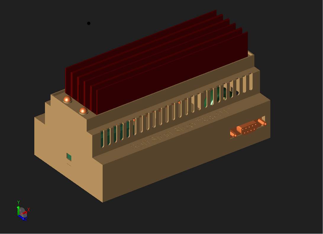 | Figure 6. Result of geometry design of the equipment (with cover on) |
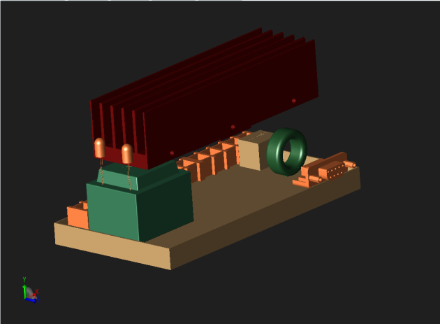 | Figure 7. Result of geometry equipment (without cover) |
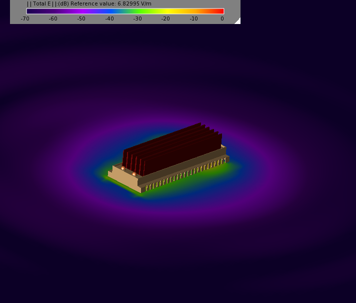
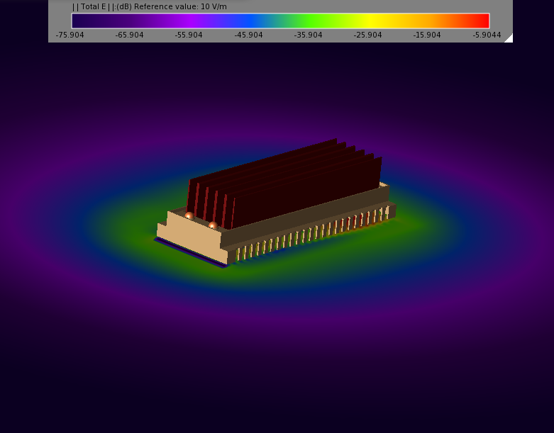
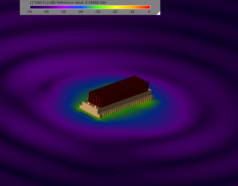
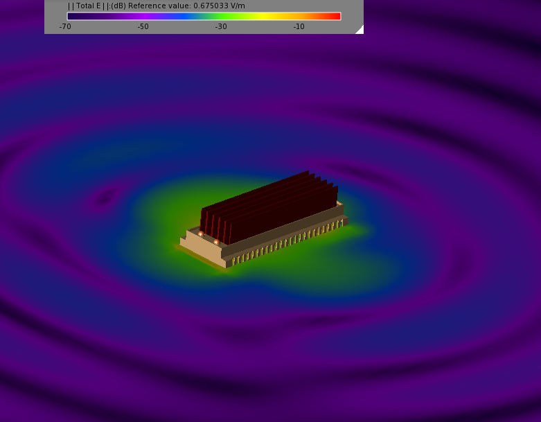
In Figure 7 the electronic components that produce electromagnetic fields, some of which are prone to result in electromagnetic disturbances are highlighted in green.The simulation is focused on the radiated emissions of the device at frequencies comparable to the tests taken in laboratory. Thus after CAD design has been imported, mechanical and electrical parameters have been set, as well as material characteristics. In order to establish if the aluminum radiator attached to the SSR for heat dissipation is acting like an antenna for the electromagnetic emissions we’ve run the simulations in two separate cases: when the SSR and the attached radiator is electrically isolated from the rest of the circuit (as it was developed) and when the SSR is connected to the ground through a capacitor which represents an estimated parasitic capacitance of 10nF between SSR and ground.The simulation has been run at 1MHz, 3MHz and 10MHz and in the following cases:When SSR (Solid State Relay) is not connected to the groundWhen SSR is connected to the ground by a capacitance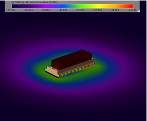 | Figure 8. Result of the simulation at 1MHz (SSR isolated) |
 | Figure 9. Result of the simulation at 1MHz (SSR connected to ground through a capacitor) |
 | Figure 10. Result of the simulation at 3MHz (SSR isolated) |
 | Figure 11. Result of the simulation at 3MHz (SSR connected to ground through a capacitor) |
 | Figure 12. Result of the simulation at 3MHz (SSR connected to ground through a capacitor) |
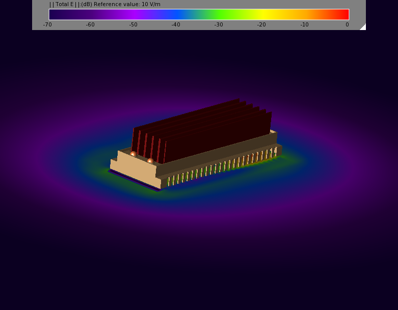 | Figure 13. Result of the simulation at 10MHz (SSR connected to ground through a capacitor) |
As seen in the pictures 8 to 13 the radiated emission remain below the limits of CISPR22, fact represented by the green area around the module. In the simulation at 3MHz the radiated emissions reach the limits of CISPR (shown in red colour) but only within the enclosure of the module and not at a 3 meters distance from it as the standard specifies. Thus the equipment under test operation will not interfere with other devices situated in its close proximity. This is an important aspect especially when the device is part of a larger system with multiple electronic devices which can be susceptible to electromagnetic radiation. The following images represent the simulation results for all tested frequency at 1MHz, 3MHz and 10MHz in he 2 cases.
5. Conclusions
Typical electronic systems are made up of several levels of packaging of two or more subassemblies connected together as application of the design for excellence (DFX) activities. The aspects regarding to EMC are very important and difficult to resolve. Proper software tool for EM modeling and simulation become an important issue in order to complete DFX methodology. The XFdtd software environment was applied in order to optimize the project of subsystem used to control the energy into vapor phase soldering equipment. The modeling and EM simulation of the developed electronic module helped show a better understanding about the radiated emissions of the device either in the case of the SSR connected to the ground or in the case of the SSR connected to the ground through a capacitor. Based on the results provided by the simulation software the radiated emissions are well below the standard levels specified by CISPR22. This has been also the case with the electromagnetical compatibility measurements taken in laboratory even at 1 meter from the test antenna which validates the simulation’s results. The highest quasi-peak level of radiated emissions recorded by the log-periodic antenna was 32.43 dB(μV)/m in the vicinity of 4MHz which is below the CISPR limit. This level of radiated emissions can be caused by the internal quartz oscillator which acts as the clock for the microcontroller and can be reduced even further by using an internal oscillator. The higher levels of conducted perturbations recorded in the laboratory measurement suggest that a below 5MHz filter is required to be installed in the supply block of the electronic device. This will lower the conducted perturbations below the limits of the CISPR standard. Above the 5MHz mark all recorded conducted emissions were within the standard’s limits. Based on comparison of the laboratory measurements and simulations results the authors were able to validate the meshing algorithm in order to extend electromagnetic modelling and simulation methodology by using the XFdtd software environment.
ACKNOWLEDGEMENTS
The authors would like to thank Scott Langdon and his colleagues from REMCOM Inc. for their continuous support with the simulations done in the XFdtd software environment and EMCLab - Electromagnetic Compatibility Laboratory, “Stefan cel Mare” University of Suceava represented by professor Eugen Coca and Georgiana Buta, Ph. D. student for the EMC tests performed. The work has been funded by the Sectoral Operational Programme Human Resources Development 2007-2013 of the Romanian Ministry of Labour, Family and Social Protection through the Financial Agreement POSDRU/88/ 1.5/S/60203.
References
| [1] | EN 55022 - "Information Technology Equipment. Radio Disturbances Characteristics. Limits and methods of measurement", 2007 |
| [2] | I. Plotog, P.Svasta, B.Mihailescu, G.Varzaru and I. Busu., “Electronic module for controlling the energy in a vapour phase soldering machine”, Conference proceedings 15th International Symposium for Design and Technology of Electronic Packaging, SIITME 2009, Gyula, Hungary, September 2009 |
| [3] | G. Buta, B. Mihailescu, E. Coca, I. Plotog and P. Svasta, “EMC Assessment for VPS technology process control module”, Conference procedings 6th International Workshop of Electromagnetic Compatibility, CEM 2009, Constanta, Romania, November 2009 |
| [4] | B. Mihailescu, I. Plotog, P. Svasta and M. Vladescu, ”VPS Control Module EMC Modeling and Evaluation”, Conference proceedings 9th Edition International Symposium on Electronics and Telecommunications, ETC, pp. 433-436, IEEE Catalog Number: CFP1003L-PRT, ISBN: 978-1-4244-8458-4, Timișoara, Romania, Noiembrie 2010 |
| [5] | B. Mihailescu, I. Plotog, P. Svasta and M. Vladescu, ”EM Simulation and Experimental Assessment of VPS process control module”, Conference proceedings IEEE 16th International Symposium for Design and Technology in Electronic Packaging, SIITME, pp. 142-143, ISBN 978-60-6551-012-8, Pitești, Romania, Septembrie 2010 |
| [6] | “EMI from Cavity Modes of Shielding Enclosures - FDTD Modeling and Measurements” by Li, Nuebel, Drewniak, DuBroff, Hubing, and Van Doren. IEEE Transactions on Electromagnetic Compatibility issue February 2000 |
| [7] | G. Buta, B. Mihailescu, E. Coca, I. Plotog and P. Svasta, “EMC Assessment for VPS technology process control module”, Conference proceedings 6th International Workshop of Electromagnetic Compatibility, CEM 2009, Constanta, Romania, November 2009 |


 Abstract
 Reference
 Full-Text PDF
 Full-text HTML