Marco Tulio C. Faria1, Edna Maria F. Viana2, Carlos B. Martinez2
1Department of Mechanical Engineering, Universidade Federal de Minas Gerais (UFMG), Belo Horizonte-MG, 31270-901, Brazil
2Department of Hydraulics and Water Resources, UFMG, Belo Horizonte-MG, 31270-901, Brazil
Correspondence to: Marco Tulio C. Faria, Department of Mechanical Engineering, Universidade Federal de Minas Gerais (UFMG), Belo Horizonte-MG, 31270-901, Brazil.
| Email: |  |
Copyright © 2014 Scientific & Academic Publishing. All Rights Reserved.
Abstract
The fish access into the draft tube of hydraulic turbines has caused numerous ecological accidents in several Brazilian hydropower plants. Many Brazilian fish species usually swim upstream for spawning and are attracted by the flow coming from the turbine tailrace pipe into the hydraulic machine. Some technical alternatives have been evaluated as feasible solutions to impede the fish entrance into hydraulic turbines. Electromechanical fish barriers appear to be a promising alternative to repel fishes from hydraulic turbine due to their small impact on the turbine flow and due to their capability of efficiently impeding the entrance of aquatic living beings into the turbine draft tube. This paper presents the development of a reduced model of an electromechanical barrier, designed to be installed on the draft tube stoplog guides, that is intended to impede the fish upstream movement through the turbine. A model of an axial-flow propeller turbine, at scale of 1:10.5, is specially designed for this work. The turbine test bench includes the turbine spiral case and draft tube, the turbine runner and the afterbay tank, which has been built to accommodate the fish individuals tested in this work. The efficacy tests of the electromechanical barrier model are performed at several operating conditions. The fish movement near the barrier is monitored by using small video cameras, which permit to record and to observe the fish reaction under the effect of electrical fields at the entrance of the turbine draft tube.
Keywords:
Environmental issues, Hydraulic turbines, Fish barrier, Electric barrier
Cite this paper: Marco Tulio C. Faria, Edna Maria F. Viana, Carlos B. Martinez, Model Development of a Fish Electromechanical Barrier for Hydraulic Turbines, International Journal of Ecosystem, Vol. 4 No. 3, 2014, pp. 159-164. doi: 10.5923/j.ije.20140403.08.
1. Introduction
It is well known that hydropower dams have been one of the main reasons for the decline of fish stocks in rivers used for electricity production [1]. Some mechanisms have been evaluated with the purpose of permitting the safe fish passage through the hydraulic turbine water circuit [2], [3]. Aiming at reducing the environmental impact of hydropower plants, the Brazilian environmental regulations require the design of fish passage mechanisms through the plant dams. However, large schools of fish enter the draft tubes, mainly during the low speed machine operations, in the attempt to swim upstream through the hydraulic machine [4]. Preliminary in-situ investigations about these events indicate that the river flow changes caused by the hydraulic turbine circuit offer ideal conditions for fish attraction. Hence the access of aquatic animals into the turbine draft tubes has led to several ecological accidents involving the fish killing, which are generally provoked by abrupt pressure variations inside the draft tube during the machine operational regime changes [5]. There are many reports of fish entrance into hydraulic turbines in Brazilian hydropower plants, but there is no data about the fish mortality rate in these events.In order to impede the fish passage upstream through hydraulic turbines, some repelling mechanisms and barriers have been thought as feasible technological solutions for this problem. Mechanical, electrical, optical, and acoustical principles have been employed to develop these mechanisms. Within all feasible repelling mechanisms, the mechanical fish barriers are the simplest and cheapest in terms of operation and maintenance costs, however they can cause considerable impact on the machine behavior [6]. The evaluation of new technologies for repelling mechanisms requires the development of experimental studies about their efficacy using prototypes or reduced models of hydrogenerators.This work presents the stages of the development of a repelling mechanism devised to impede the fish entrance into hydraulic turbines based on electromechanical principles. The proposed mechanism combines the concept of mechanical barrier, which can be easily installed on the stoplog guides, and the concept of repelling system based on electrical field. The electromechanical barriers seem to be a promising alternative for the fish entrance problem, since they not only cause small perturbations on the turbine flow but also can repel efficiently aquatic species that try to enter the draft tube. A reduced model at the scale of 1:10.5 of the axial propeller turbine from the hydropower plant of Itutinga, which is located at the state of Minas Gerais, Brazil, is designed and mounted in laboratory to evaluate preliminarily the efficacy of the proposed electromechanical barrier. All stages in the design and manufacture of the axial propeller turbine reduced model are described in this work. Preliminary operating tests of the electromechanical barriers are performed to evaluate the mechanism efficacy to repel fishes from hydraulic turbines.
2. The Axial Turbine Model
The development of the turbine reduced model, at the scale of 1:10.5, is based on the following requirements: i. availability of technical data about geometric characteristics of the prototype hydraulic and mechanical components; ii. adjustment of the reduced model dimensions to the laboratory infrastructure; iii. possibility of using the barrier model concept in a full scale prototype. The axial turbine of the Itutinga hydropower plant, situated in the state of Minas Gerais, Brazil, is chosen for this work. The design of the turbine reduced model can be divided into nine parts: 1. spiral case; 2. draft tube; 3. rotating system; 4. turbine distributor vane; 5. water intake system; 6. downstream afterbay tank; 7. supporting structure; 8. hydraulic circuit; 9. electromechanical barrier. The description of the most important design and manufacture stages of the model hydraulic, structural, and mechanical components is presented below.
2.1. Manufacture of the Model Spiral Case and Draft Tube
The manufacture of the turbine model spiral case and draft tube follows five basic steps [7]: a) tridimensional (3D) geometric modeling; b) generation of the sections of the tridimensional models; c) assembly of the sections using solid foam; d) surface rectification using plaster; e) fiberglass lamination. Figure 1 depicts the 3D drawings of the model spiral case and draft tube. The generation of the sections cut from the 3D models is shown on Figure 2.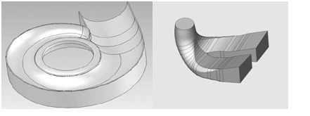 | Figure 1. 3D drawings of the model spiral case and draft tube |
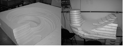
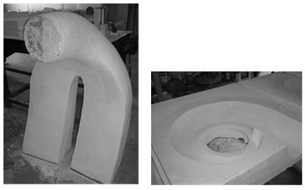
Plates of solid foam are cut and glued on each section shown on Figure 2. Figure 3 shows the assembly of the solid foam sections used to render the 3D models associated with the spiral case and draft tube. The last step in the construction of the 3D component models is the surface rectification by using plaster as depicted on Figure 4. 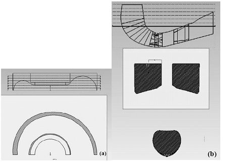 | Figure 2. Sections generated by slicing the 3D geometric models |
 | Figure 3. Photographs of the assembly of the foam plates to produce the spiral case and draft tube models |
 | Figure 4. The solid foam models after the geometric rectification by using plaster |
Finally, fiberglass lamination process is employed to manufacture the spiral case and draft tube models, as shown on Figure 5. The choice for fiberglass lamination is based on three aspects: 1. simple manufacturing process; 2. good mechanical strength and low weight of fiberglass components; 3. excellent surface strength to the deterioration process caused by water flows.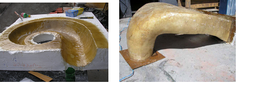 | Figure 5. Fiberglass lamination process of the spiral case and draft tube models |
2.2. Manufacture of the Turbine Rotating System and Distributor Vane
The manufacture of the turbine rotating system and distributor vane is based on the following steps: 1.elaboration of the technical drawings for the machining process; 2.machining process by using CNC machine tools; 3.assembly of the mechanical parts by using welded joints and screws. Figure 6 shows the 3D drawings made for the manufacturing process employing CNC machine tools.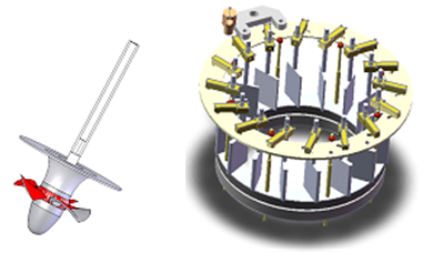 | Figure 6. 3D drawings of the turbine model rotating system and distributor vane |
The turbine runner shaft is made with stainless steel. The turbine runner body and blades, and the turbine inlet cone are manufactured by employing aluminum. Figure 7 shows a picture of the turbine model runner and inlet cone, which is mounted on the runner body to direct the incoming flow. In the computation of the runner shaft diameter, the hydraulic pressure loads, the weight, and eventual overload effects are accounted for. The runner shaft supporting system uses three rolling-element bearings. A thrust ball bearing is selected to support the vertical rotating system, which is composed of the turbine shaft, the runner, and all rotating components. Two radial ball bearings are employed as guide bearings for the vertical axial propeller turbine model.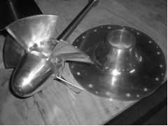 | Figure 7. Photograph of the turbine runner mounted on its shaft and of the inlet cone |
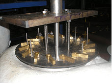
The distributor guide vanes and connecting rods are made with brass, the assembly flanges for the distributor vane are manufactured with aluminum, and the screws are made with stailess steel. Figures 8 and 9 depict photographs of the model distributor vane. The initial stage of the distributor vane assembly on the model spiral case is depicted on Figure 8. A photograph of the vane driving circular plate and connecting rods mounted on the spiral case is shown on Figure 9. 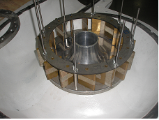 | Figure 8. Photograph of the distributor vane assembly on the model spiral case |
 | Figure 9. Photograph of the vane driving plate and connecting rods on the model spiral case |
2.3. Assembly of the Axial Turbine Model with Electromechanical Barriers
Three very important items in the turbine model assembly are the water intake system, the downstream tank, and the electromechanical barriers. The water intake of the turbine model is performed by a set of two 20 hp hydraulic pumps controlled by frequency inverters. The afterbay tank is specially designed to allow experimental tests with living fishes in laboratory. The tank volumetric capacity is about 30m3. The tank metallic frame is built with commercial steel beams and its walls are manufactured by fiberglass lamination, as shown on Figure 10. 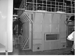 | Figure 10. Photograph of the turbine model afterbay tank |
The installation of an electromechanical barrier must cause miminum interference in the operation and maintenance of the hydrogenerator unit. Also the location of the repelling mechanism must be chosen to restrict efficiently the fish upstream movement. Hence, the more appropriate place for mounting the electromechanical barrier is the stoplog (draft tube gate) guides, as it is shown schematically in Figure 11.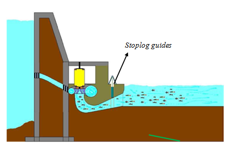 | Figure 11. Schematic drawing of a hydrogenerator unit indicating the location for installation of the fish barrier [8] |
The selected selected repelling mechanism consists of an acrylic gate with two lower openings. On the gate opening transverse bars there are horizontal metallic parallel plates, as depicted on Figure 12. These plates are connected to an external power source to permit the creation of repelling electrical fields, working as electrodes. Two electromechanical barriers are installed on the stoplog (draft tube gate) guides, which have been introduced into the model draft model.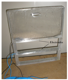 | Figure 12. Photograph of the electromechanical barrier made with acrylic resin |
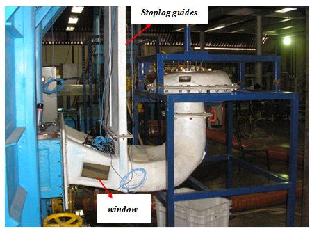
The basic dimensions of the barrier opening shown in Figure 12 are the width of 377mm and the height of 103mm. The electromechanical barrier design must meet two basic requirements: 1.very small water head loss in the stoplog; 2.uniform electric field within electrodes. Parallel electrodes present a very simple geometry and can provide electric fields with almost uniform flux lines [8]. It is noteworthy to say that the fish barrier described in this work can be used in prototypes in full mode operation due to the large spacing between electrodes which cause very small hydraulic head losses at the nominal turbine operating conditions.Figure 13 depicts the mounting of the electromechanical barrier in the model stoplog guides. A picture of the whole assembly of the axial propeller turbine model can be viewed on Figure 14. The part formed by the spiral case and draft tube is supported by a metallic structure frame. Two fiberglas columns are mounted on the draft tube tailrace pipe, as shown in Figure 14, to represent the turbine stoplog guides. The electromechanical fish barriers are installed in the draft tube guides. Transparent windows are placed at the side walls of the draft tube pipes to allow the visualization of the fish movement inside the draft tube. 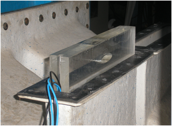 | Figure 13. Electromechanical fish barrier mounted in the draft tube stoplog guide |
 | Figure 14. Photograph of the axial turbine model with electromechanical fish barriers |
3. Fish Barrier Test Methodology
The preliminary tests to evaluate the efficacy of the electromechanical barrier in repelling fishes in the turbine draft tube are performed by varying the hydraulic pumps operating speed and the electrical voltage on the barrier electrodes. The hydraulic pumps are driven by frequency inverters that allow the pump speed control. The barrier electrodes are connected to a varivolt that permits to vary the applied voltage. Video files of the fish motion inside the draft tube are generated through the draft tube windows during the tests. The experimental apparatus used in the preliminary efficacy tests of the electromechanical barriers comprises the following items: 1. An axial propeller turbine testing bench (Figure 14), which has been built with geometric similitude, at a scale of 1:10.5, to the prototype installed in the Itutinga power plant; 2. two frequency inverters 20 hp WEG CFW09; 3. two 20 hp hydraulic pumps EH, model HF150, 1750rpm; 4. a varivolt Vortex M-2412, 0-240V; 5. two multimeters Minipa ET-2042C to monitor the electrode current and voltage; 6. two small digital web cameras to record the videos during the tests; 7. two personal computers to acquire and store the video files; 8. two 40W red lights (spot ligths). Figure 15 shows a photograph of the web camera and the spot red light mounted at the draft tube window. 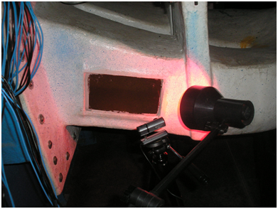 | Figure 15. Photograph of the video monitoring system mounted at the draft tube window |
In order to perform the fish barrier efficacy tests, forty nine (49) individuals of the fish species Pimelodus maculatus (mandi) are placed in the afterbay tank for conditioning into the new environment. This number represents the individuals available in laboratory for these tests. The choice of the species Pimelodus macalutus is due basically to its greater tolerance to electrical stimuli comparatively to all other fish species found in the rivers of Minas Gerais [8]. All tests must be performed after 6 p.m., when the incidence of natural lights on the turbine test bench is too small. The ceiling lights are kept off during the tests to avoid any light effect on the fishes. The test procedure employed to evaluate the electromechanical fish barrier efficacy can de described in the following steps:1. Step 1: Position the video web cameras and the red spot lights in front of the draft tube side windows.2. Step 2: Turn on the computers and prepare the recording programs to acquire the image files from the two draft tube windows.3. Step 3: Turn on the fish barrier electrodes and set the desired voltage by adjusting the varivolt. The voltage level is read by a multimeter with resolution of 0.1V. Four voltage levels are used in these preliminary tests: 50V, 40V, 30V e 20V.4. Step 4: Command the frequency inverters to start up the hydraulic pumps until reaching the pump nominal speed of 1750rpm. Six pump speeds are chosen to perform the tests - 1750rpm (nominal), 1520rpm, 1290rpm, 1060rpm, 830rpm e 600rpm - for each selected barrier voltage level. The tests always begin with the maximum pump operating speed.5. Step 5: Start the video recording of the fish movement inside the draft tube. Each video recording lasts about 9 minutes. Six video files are generated for each voltage level. The first video file is associated with the pump nominal speed. 6. Step 6: Change the electrode voltage level and repeat steps 5 and 6.7. Step 7: Turn the frequency inverters off and close the draft tube entrance. Turn the varivolt off. The planned tests for the day are finished.The displays of the frequency inverters show the rotational speed of the two hydraulic pumps and not the turbine speed. The turbine rotational speed is measured during the tests using the optical tachometer Minipa MDT-2244B. The curve of the turbine speed versus the pump speed is shown on Figure 16. The maximum turbine speed is approximately 675rpm when the maximum pump speed is 1750rpm.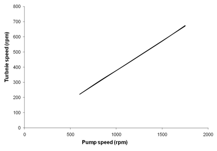 | Figure 16. Curve of the axial turbine speed in function of the hydraulic pumps speed |
4. Test Results and Analysis
The results from more than 40 tests are recorded in 30 video files describing the fish activity inside the draft tube. During the tests there was not a single record of any individual crossing the electromechanical barrier in direction to the turbine. The preliminary tests consumed more than 25 hours of turbine operation. Some comments about the test results are listed as follows: (1) The combination of high voltages (50V in the electrodes) with high flow speeds (1750rpm in the pumps) had an apparently efficacious effect on repelling fishes. In these operating conditions, the video files do not register any individual entering the draft tube tailrace pipe. (2) Few individuals tried to enter the draft tube visualization region, swimming in direction to the stoplog, at high flow condition (1750rpm in the pumps) and medium voltage level (30V). (3) At low pump speeds (below 1290prm), it was observed the presence of individuals in the draft tube region of visualization at all voltage levels. At high voltages (50V and 40V), the fish scaping movement from the draft tube was more intense. (4) Long stays of the same school of fishes in the tank can permit a quick adaptation to the environment, which may affect the test results. In the first day of tests, the amount of individuals entering the draft tube visualization region was larger than the amount of fishes observed in the following days of tests, at the same testing conditions. In order to avoid the effect of fish conditioning on the barrier repulsion tests, it is recommended to replace the group of fishes every day. (5) Two deaths were observed along the tests in the group of 49 individuals. The first death occurred sometime after the first tests. Probably, this first death was caused by problems in the water temperature or oxygenation. The second death happened in a young individual, with damage on its gills, which has been likely caused by electrical shock. In these two events, the death occurred afterward the barrier tests. (6) In some tests, in which there was not register of fish activity in the draft tube tailrace pipe, the pump speed was reduced to stimulate the fish entrance. However, in some tests at 20V, no individual entered the draft tube visualization region, even at zero speed. This observation supports the hypothesis of fish conditioning to the environment after some time period. Two main drawbacks of the preliminary tests performed to evaluate the electromechanical fish barrier were the small number of fish samples and the short period of observation. Even though experimental studies about the influence of machines and equipments on living beings require long times for observation and analysis, the results obtained in the preliminary efficacy tests of the electromechanical fish barrier indicate the great potential of this technology to build feasible mechanisms to repel fishes from hydraulic turbines. Further research about the efficacy and efficiency of electromechanical fish barriers is a crucial need for the development of this technology.
5. Final Remarks
The results rendered in the preliminary efficacy tests of the electromechanical barrier show that this technology can be a good alternative to mitigate the environmental problems associated with fish killing at the draft tube of hydraulic turbines. The technical literature lacks studies about any electromechanical mechanism used in the turbine draft tube to repel fishes. The reduced model of the axial turbine of Itutinga hydropower plant represents an important step in the consolidation of a test center for hydraulic turbines, which can have adequate laboratory infrastructure to study the environmental impact of turbines on fishes. This research represents an important methodological advance on the study of hydraulic machines, since it allows put together the machine behavior requirements and the environment preservation demands in the investigation of hydraulic turbines and aquatic wild life interactions.More tests in the turbine bench developed in this work certainly will provide important technical data to anticipate design and operating problems in a electromechanical fish barrier prototype. Fast and efficient assembly procedures, maintenance routines for the mechanical and electrical parts, safe operation of the driving system, and the development of efficient isolation systems can be studied in laboratory using the reduced model developed.
ACKNOWLEDGEMENTS
The authors would like to express their thanks to ANEEL (Brazilian National Agency of Electrical Power), CEMIG (Electricity Company of Minas Gerais, Brazil), and FAPEMIG (Foundation for Research Support of Minas Gerais, Brazil) for the financial support provided for the development of this work. The authors also wish to express their sincere thanks to the former graduate students Flavio Nakamura Silva and Rafael Emilio Lopes, from the Department of Electrical Engineering at UFMG, and to the former undergraduate student Rodrigo Gomes Louzada, from the Department of Mechanical Engineering at UFMG, for their crucial assistance and support in this work.
References
| [1] | J. J. Brown, K. E. Limburg, J. R. Waldman, K. Stephenson, E. P. Glenn, F. Juanes, and A. Jordaan, 2013, Fish and hydropower on the U.S. atlantic coast: failed fisheries policies from half-way technologies., Conservation Letters, 6(4), 280-286. |
| [2] | C. V. Burger, J. W. Parkin, M. O´Farrell, A. Murphy, and J. Zeligs, 2013, Non-lethal electric guidance barriers for fish and marine mammal deterrence: a review for hydropower and other applications, Proc. HydroVision International Conference and Exhibition 2013, Denver, Colorado, 1-31. |
| [3] | D. Schowalter, and K. Kuehlert, 2005, Fishing for solutions, International Water Power & Dam Construction, 57(9), 28-30. |
| [4] | C. S. Abernethy, B. G. Amidan, and G. F. Cada, 2003, Fish passage through a simulated horizontal bulb turbine pressure regime: a supplement to laboratory studies of the effects of pressure and dissolved gas supersaturation on turbine-passed fish, Report prepared for the U.S. Department of Energy, Contract DE-AC06-76RL01830, USA. |
| [5] | L. A. Garrison, R. K. Fisher, M. J. Sale, and G. F. Cada, 2002, Application of biological design criteria and computational fluid dynamics to investigate fish survival in Kaplan turbines, Proc. HydroVision International Conference and Exhibition 2002, Kansas City, Missouri, 1-12. |
| [6] | M. T. C. Faria, O. G. Paulino, F. H. Oliveira, B. H. Barbosa, and C. B. Martinez, 2010, Influence of mechanical draft tube fish barrier on the hydraulic thrust of small Francis turbines, ASCE Journal of Hydraulic Engineering, 136(11), 924-928. |
| [7] | M. T. C. Faria, C. B. Martinez, and E. M. F. Viana, 2009, Methodology for manufacturing mini hydraulic turbines using composite materials, Proc. 8th Latin American Congress on Electricity Generation and Transmission, Ubatuba, São Paulo, Brazil, 1-7 (In Portuguese). |
| [8] | R. E. Lopes, 2009, Study of electrical barriers for impeding the fish entrance into hydraulic turbines, Ph.D. dissertation, Electrical Engineering Graduate School, Universidade Federal de Minas Gerais, Brazil (In Portuguese). |


 Abstract
 Reference
 Full-Text PDF
 Full-text HTML