Rodolfo Costa de Medeiros1, Johnny Soares de Carvalho2, Felipe Nascimento Arroyo2, Diego Henrique de Almeida2, Tiago Hendrigo de Almeida3, André Luís Christoforo2, Francisco Antonio Rocco Lahr4
1Laboratory of Wood and Timber Structures (LaMEM), São Carlos Engineering School, São Paulo University (USP), São Carlos, Brazil
2Department of Civil Engineering (DECiv), Federal University of São Carlos (UFSCar), São Carlos, Brazil
3Department of Materials Engineering (SMM), Engineering School of São Carlos (EESC), São Paulo University (USP), São Carlos, Brazil
4Department of Structures Engineering (SET), Engineering School of São Carlos (EESC), São Paulo University (USP), São Carlos, Brazil
Correspondence to: André Luís Christoforo, Department of Civil Engineering (DECiv), Federal University of São Carlos (UFSCar), São Carlos, Brazil.
| Email: |  |
Copyright © 2018 Scientific & Academic Publishing. All Rights Reserved.
This work is licensed under the Creative Commons Attribution International License (CC BY).
http://creativecommons.org/licenses/by/4.0/

Abstract
This research analyzes the forces in bracing members of timber trusses through numerical modeling using the computational system Strap, considering the three-dimensional structure behavior. The values obtained are compared to values set by the Brazilian standard ABNT NBR 7190 (1997), which considers the side instability of the bracing elements. The results were also compared with the values proposed by the methods of the European standard EUROCODE 5, the South African Standard SABS 0163 (1994) and with the work developed by Underwood (2000). The computer models represent industrial sheds with 12 to 24 meters spam, 24 to 96 meters long with heights of pillars 3, 4 and 6 meters. The structural models analyzed were the Pratt and Howe truss types, considering wood provide from C30 and C40 strength classes. The results show that the forces acting on the bracing of the three-dimensional models are higher than the values obtained by the method of ABNT NBR 7190 (1997), and the values obtained by the methods proposed by EUROCODE 5 and Underwood (2000) are more reliable in the overall behavior of the structure.
Keywords:
Bracing, Timber structures, Trusses, Numerical analysis
Cite this paper: Rodolfo Costa de Medeiros, Johnny Soares de Carvalho, Felipe Nascimento Arroyo, Diego Henrique de Almeida, Tiago Hendrigo de Almeida, André Luís Christoforo, Francisco Antonio Rocco Lahr, Forces in Bracing Elements of Timber Trusses, International Journal of Construction Engineering and Management , Vol. 7 No. 1, 2018, pp. 29-34. doi: 10.5923/j.ijcem.20180701.03.
1. Introduction
Wood is a natural material and presents an excellent relation between mechanical strength and density, which makes it suitable for use in civil construction, especially in roofing structures [1-3].Bracing is a structural subsystem of flat structures locking in order to maintain the elements stability that compose it [4, 5]. This subsystem ensures that the structure works according to stability criteria considered in design for each constituent structure element, an aspect that will be directly reflected in the functions for which environments are constructed.Trusses are one of the most commonly used forms of flat structure in buildings, and in this type of structural system, bracing is an indispensable for structural elements stability and overall structure. The operation of each element depends on the bracing system arrangement, and its sizing must be carried out according to this provision [6].The current bending stress calculation model presented by the Brazilian standard ABNT NBR 7190 [7] considers the warped elements lateral instability with order curvature of L/300. Besides this, the mentioned document mentions in item 7.6.4: "in each node belonging to compressed limb of the main system elements, a force transverse to the main element, with intensity F1d = Nd/150" must be considered. This structural model of flat trusses is simplified by the technology and computational tools available today. Although the flat model presents satisfactory results, it omits the bracing influence in three-dimensional structure and the forces acting on bracing elements.Three-dimensional models that represent the complete structure present efforts in the bracing elements that can be significantly higher than values established by standard ABNT NBR 7190 [7] in stresses estimating, resulting in values against the structures safety.Previous work by Rocco Lahr et al. [8] has dealt with a similar theme, addressing particular cases of bracing in structures. These authors have already pointed to the lower results obtained with criteria application of NBR 7190 [7], and concluded that more comprehensive studies are necessary to make possible the results generalization.In this way, it is evident the convenience of being developed more studies on three-dimensional behavior of covering structures, so that they are considered as safer values of forces in bracing pieces, in the case of a rigorous structural analysis.In this context, the present work aimed to determine, with aid of numerical tool for structural analysis in two and three dimensions, the normal forces acting on bracing elements of structures that represent sheds with trusses of wood type Pratt and Howe, and compare the values obtained with estimated values of the Brazilian standard NBR 7190 [7] and other international standards.
2. Materials and Methods
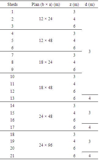
It was considered 21 base geometries of industrial wood structures sheds, as shown in Table 1, with “a” being the length, “b” width, “z” the height and “d” being span between trusses, all measures expressed in meters. All models have 25% incline roof. The trusses were divided into frames with 1.50 meters of distance between amounts. Trusses spans are 12, 18 and 24 meters and the pillars are of heights 3, 4 and 6 meters.Table 1. Sheds studied dimensions (in meters [m])
 |
| |
|
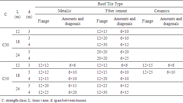
The combination of various shed dimensions configurations, spans between trusses, trusses types, bracing considerations, strength classes and roof tiles types (metal, ceramic, fiber cement), resulted in the generation of 299 models. The largest coming from shed 20 (Table 2), consisting of 1122 nodes and 3667 bars. The computational models were made in STRAP® 2008 program (Structural Analysis Programs), based on Finite Element Method (MEF).Table 2. Sections dimensions of the truss bars (in centimeters [cm])
 |
| |
|
Complete sheds structures (Fig. 1) and the isolated plane trusses were also modeled, making it possible to obtain the calculation forces (Fd) values by means of methods proposed by the norms considered.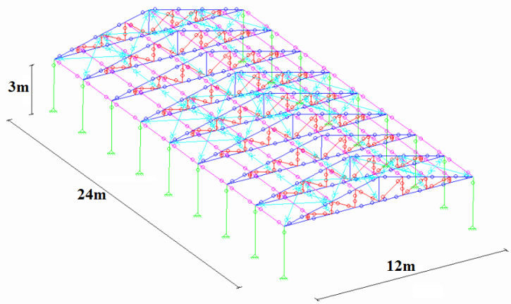 | Figure 1. Example of a shed configuration for three-dimensional analysis |
The bars properties were considered according to dimensions shown in Table 2. The bars bonds were considered bi-labeled, except in the pillar-to-soil bonding, where they were considered embedded. Only tensile were considered in steel bracing bars, with an elasticity modulus of 195 GPa. The elasticity modulus adopted for the woods was 8120 MPa and 22000 MPa, referring to the resistance classes C30 and C50 respectively [9], and reduced by correction coefficient Kmod = 0.56.Active actions were determined according to the wood class, roof tile type (metallic, fiber cement, ceramics) and static wind actions determined according to Brazilian standard ABNT NBR 6123 [10].For the roof tiles, the load of 50 N/m² for metallic tiles, 180 N/m² for fiber cement and 800 N/m² for ceramic roof tiles was considered.The wind actions were considered for the industrial zone of the São Carlos (SP) region, with the wind characteristic velocity equal to 40 m/s. The internal pressure coefficients were considered as the most unfavorable cases of building openings. It was also evaluated the cases of insulated roofs, without sealing walls.In order to analyze all the action actions hypothesis, eight shipments and nine combinations were created. The combinations represent the possible wind performance forms, the first consisting in its absence and the other alternating the different hypotheses of shed.The combinations follow the item 5.7 procedures of Brazilian Standard ABNT NBR 7190 [7] for last normal combinations. As it is considered only a variable action, the wind, all actions values were multiplied by 1.4 adopting Equation 1. | (1) |
Where: - Fd = calculating force;- γGi = permanent actions coefficient;- FGi,k = characteristic permanent forces;- γQ = increase variable actions coefficient;- FQ1,k = main variable force characteristic;- ψ0 = minority coefficient of variable actions simultaneity;- FQj,k = characteristic variable forces.In relation the simulations, it should be noted that it is a physical and geometric linear structures analysis to obtain the maximum forces values in the most unfavorable combinations.Methods of estimating the calculation force (Fd) in bracing proposed by normative documents consider the lateral structural elements instability. The methods proposed by Brazilian standard ABNT NBR 7190 [7], European standard EUROCODE 5 [11], Underwood [12] and by the South African standard SABS 0163 [13] present similar formulations, expressed in Equations 2, 3, 4 and 5, respectively. It is evident that the Brazilian standard provides an estimate of Fd value lower than the international standards values mentioned above and also lower than the value proposed by Underwood [12].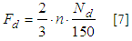 | (2) |
 | (3) |
 | (4) |
 | (5) |
From Equations 2 to 5:- PL = force on each side bracing element;- PA = maximum axial force on trusses due to permanent load;- N = constraints number along the trusses;- Nd = maximum force on contraband bar;- n = contraband trusses number.The N value in the method proposed by South African standard SABS 0163 [13] was adopted for the case of a smaller lateral restrictions number, in the case of one every two knots contravened, resulting in N = 3 for trusses of 12 meters, N = 5 for 18-meter trusses and N = 7 for 24-meter trusses. It should be noted that the calculation approaches proposed by standards considered use only the trusses flat analysis and that the bracings forces are obtained from the maximum compressed flange axial force and the number of trusses. The three-dimensional structural model analysis, which considers the bracing operation as part of overall structure, may result in values higher than those estimated by Brazilian standard method. Thus, may be underestimating the forces acting on bracing.
3. Results and Discussions
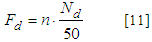
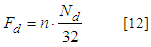
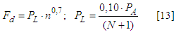
Fig. 2 shows the results variations of the bracing maximum forces for 21 shed configurations evaluated with roof tile by fiber cement tiles, considering the three-dimensional models (Models), those proposed by standards ABNT NBR 7190 [7], EUROCODE 5 [11], SABS 0163 [13] and by Underwood [12].It can be seen from Fig. 2 that the evaluation model recommended by NBR 7190 [7] leads to values much lower than Eurocode 5 (about one third for cases where the acting force magnitude is higher). Considering the values obtained by Underwood [12], the difference for the standard NBR 7190 [7] is even greater (around one fifth).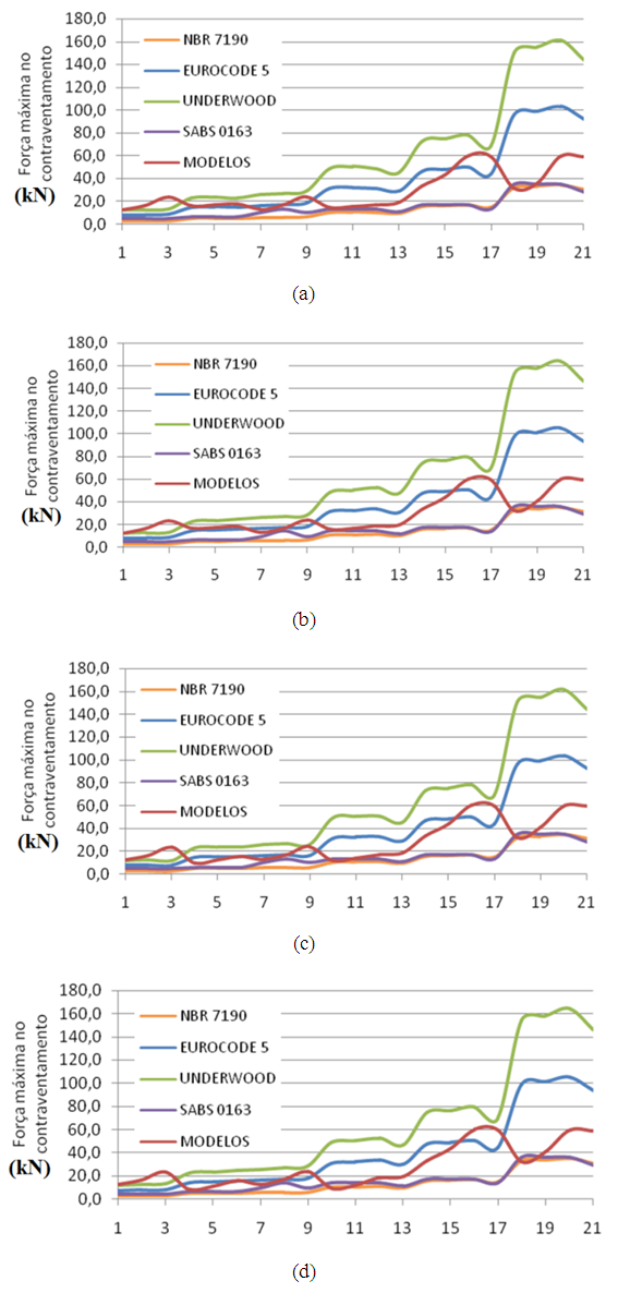 | Figure 2. Methods comparison to obtain the bracing maximum force for trusses with fiber cement roof tiles: (a) Howe, class C50; Howe, class C30; (c) Pratt, class C50 with cables; (d) Pratt, class C30 |
The underestimation consequences may lead to insufficient bracing bars sizing and compromise the structural set performance.Fig. 3 shows the results variation of the bracing maximum forces for 21 shed configurations evaluated with coverage by metallic roof tiles.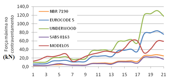 | Figure 3. Methods comparison to obtain the bracing maximum strength for Pratt trusses, C50 strength class and metal roof tiles |
Analogous comments apply here to those indicated on the results shown in Fig. 2, with percentage differences in the same order of magnitude.Fig. 4 presents the results variation of the bracing maximum forces for 21 shed configurations evaluated with coverage by ceramic roof tiles.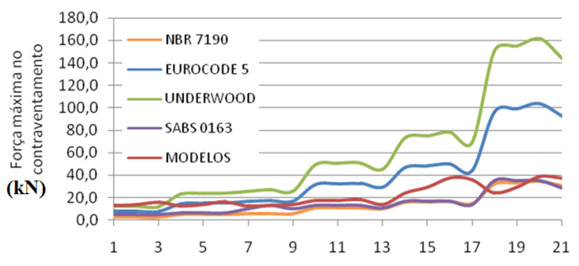 | Figure 4. Methods comparison to obtain the bracing maximum strength for trusses with ceramic roof tiles |
In this case, once again, comments analogous to those indicated on the results shown in Fig. 2 are valid, with percentage differences in the same order of magnitude. Fig. 5 illustrates the maximum compression force variation in flange for the evaluated structures.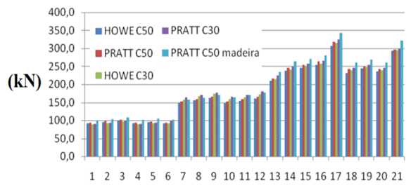 | Figure 5. Flanges maximum compression force - comparison between structures |
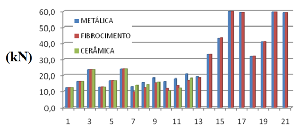
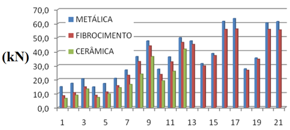
The results shown in Fig. 6 to 9 are complementary information regarding the order of magnitude of the flanges forces acting (tablets and traction) of structures studied. They are examples that quantify the differences in bar solicitations when applying three roof tiles types, namely ceramic, metal and fiber cement.Figure 6 illustrates the maximum compression force variation in bracings for structures evaluated. Figure 7 illustrates the maximum compression force variation in flange according to the roof tiles types. Figure 8 shows the maximum compressive force variation in bracings depending on the roof tile types. Figure 9 shows the variation of the maximum tensile force in bracings depending on the roof tile types.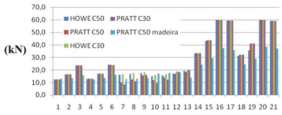 | Figure 6. Bracings maximum compression force - comparison between structures |
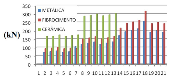 | Figure 7. Flanges maximum compressive force - comparison between roof tile types |
 | Figure 8. Bracings maximum compression force - comparison between roof tile types |
 | Figure 9. Bracings maximum tensile force - comparison between roof tile types |
It is observed that, in the case of lighter roof tile (metallic and fiber cement), the bracing bars actions are higher due to the greater wind action contribution to the structure, showing that in such situations, more attention must be given to the bracing bars evaluation.
4. Conclusions
The method proposed by Brazilian Standard ABNT NBR 7190 [7] presented all values of normal calculation force lower to the computational models.The European EUROCODE 5 [11] method provided values higher than the others in about 75% of the cases investigated. For models with wood bracing, the margin of values higher than the computational models increases to 85%.The method presented by Underwood [12] presented higher values in about 90% of the models studied.The method adopted by SABS 0163 [13] presented lower values than almost all the models.The changes in trusses type (Howe and Pratt), strength class (C30 and C50) and roof tile type (metal, fiber cement and ceramic) in the models showed close values, with slight variations, of the maximum compression forces in the trusses frames and bracing.The model with wood bracing presented maximum forces values in the bracing lower to the models with steel bracing.In summary, the underestimation consequences of normal forces on bracing elements can lead to insufficient bars sizing, compromising the mechanical structure performance.
ACKNOWLEDGMENTS
Authors thank to Wood and Timber Structures Laboratory (LaMEM), Structural Engineering Department (SET), São Carlos Engineering School (EESC), São Paulo University, by the materials and resources used in this research.
References
| [1] | Cheung, A. B.; Martinez, M. E.; Calil Junior, C. Resistência característica e intervalos de confiança para treliças de madeira com ligações de chapas com dentes estampados. Revista madeira: Arquitetura e Engenharia, São Carlos, v. 16, p. 35-45, 2005. |
| [2] | Christoforo, A. L.; Silva, S. A. M.; Panzera, T. H.; Rocco, F. A. L. Estimative of Wooden Toughness by the Apparent Density and Bending Strength. International Journal of Materials Engineering, v. 4, p. 49-55, 2014. |
| [3] | Almeida, T. H.; Almeida, D. H.; Christoforo, A. L.; Chahud, E.; Branco, L. A. M. N.; Lahr, F. A. R. Density as estimator of strength in compression parallel to the grain in wood. International Journal of Materials Engineering, v. 6, p. 67-71, 2016. |
| [4] | Fernandez, B. O.; Molina, J. C.; Calil Jr., C. Estudo numérico-experimental do sistema de treliças modulares para pontes de madeira. Cadernos de Engenharia de Estruturas (Online), v. 13, p. 33-50, 2011. |
| [5] | Christoforo, A. L.; Romanholo, G. A.; Panzera, T. H.; Borges, P. H.; Rocco, F. A. L. Influence of stiffness in bolted connections in wooden plane structure of truss type. Eng Agr-Jaboticabal, v. 31, p. 998-1006, 2011. |
| [6] | Demarzo, M. A.; Rocco, F. A. L.; Christoforo, A. L. Choice optimization of species for design of wood truss structures by computer method. In: XI World Conference on Timber Engineering (WCTE 2010), 2010, Trentino, Itália. |
| [7] | Associação Brasileira De Normas Técnicas. NBR 7190. Projeto de estruturas de madeira. Rio de Janeiro, ABNT, 1997. |
| [8] | Rocco Lahr, F. A.; Calil Jr, C.; Arita, A. S.; Amorim, A. R.; Cunha, M. O. Contribuição do contraventamento no cálculo de estruturas treliçadas espaciais de madeira. In: XI Encontro Brasileiro em Madeiras e em Estruturas de Madeira, Londrina, PR., 2008. |
| [9] | Calil Jr., C. South America Timber Structures Code. Concepción, Chile: Proceedings of the 51st International Convention of Society of Wood Science and Technology, 2008. |
| [10] | Associação Brasileira De Normas Técnicas - ABNT - NBR 6123. Forças devidas ao vento em edificações. Rio de Janeiro, ABNT, 1988. |
| [11] | European Standards - EN - EUROCODE 5: Design of Timber Structures. CEN, Brussels, 2003. |
| [12] | Underwood, C. R. Permanent bracing design for MPC Wood roof truss webs and chords. Master of Science Thesis, Blacksburg: Virginia Polytechnic Institute and State University, 2000. |
| [13] | South African Bureau of Standards - SABS - 0163. The structural use of timber. Pretoria, 1994. |

 Abstract
 Reference
 Full-Text PDF
 Full-text HTML